All published articles of this journal are available on ScienceDirect.

Aerodynamic Admittance Research on Wide-body Flat Steel Box Girder
Authors Info & Affiliations
Abstract
Aerodynamic admittance is a key parameter affecting the analysis accuracy of the bridge buffeting response. However, few articles have covered the issue of the wide-body flat box girder with much smaller depth-width ratio (such as 1/12 studied in this paper). Therefore, to explore the real buffeting force of the wide-body flat box girder, experiments of the static force coefficients and aerodynamic admittance are carried out in wind tunnel. Wooden segmental model has a scale ratio of 1/60 to an actual 42 m wide suspension bridge girder. Using the high-frequency-force-balance (HFFB) equipment fixed with the segmental model under the conditions of different wind speeds and different wind attack angles, wind power spectrums of the buffeting force are measured and the variation of aerodynamic admittance parameters is analyzed. The results show that the aerodynamic admittance of the box girder measured in the experiment with this so much smaller depth-width ratio differs from the corresponding classical Sears expression. Some inspiration can be presented for the future study of the buffeting response for this kind of much wider bridge with the similar ratio in this paper.
1. INTRODUCTION
With the increase of span, bridge wind induced vibration is more and more obvious. Buffeting response of long-span bridges is one of the main wind induced vibration forms, and hence predicting the buffeting response is important for the bridge safety. Aerodynamic admittance, however, is the link between the random wind load and the bridge structure. It is a key function affecting the analysis accuracy of the buffeting response. Davenport buffeting force expression has been widely used for many years which introduced the aerodynamic admittance for the first time. From then on, the unsteady buffeting force response and the fluctuating wind without complete correlation along the lateral bridge were closely combined together. Aerodynamic admittance has been investigated through the theoretical analysis and wind tunnel test over these years.
Rasmussen [1] introduced a model for simulating the two-dimensional turbulence through discrete vortex method by seeding the upstream flow with vortex particles. And he presented another random method generating a synthetic turbulent flow field to simulate the effect of the incoming turbulent flow toward a bridge deck cross-section in the atmospheric boundary layer five years later [2]. Argentini [3] used the distributed representation to analyze the unsteady forces acting on a simple closed-box single girder deck. Tomasini [4] described an algorithm to define non-stationary aerodynamic forces, which considered the spatial correlation of the wind through the aerodynamic admittance function. Han [5, 6] made an accurate identification of the aerodynamic characteristics of vehicles and bridge at the premise of the coupled vibration analysis with a wind-vehicle-bridge system. Guo [7] found that the side force and rolling moment coefficients of the vehicle were efficiently reduced by a single-side wind barrier, but for the bridge deck these values were increased. Prud'homme [8] studied the influence between the sway movement and motion axis on flutter and vortex induced vibration in a 3 DOF wind tunnel test. Zhu [9] studied the aerodynamic force distribution characteristics of a twin-box bridge deck by wind tunnel pressure test. Zhao [10] gave a new bridge deck aerodynamic admittance function with the feasibility validation between the numerical simulation and the wind tunnel test. Massaro [11] investigated the effect of three-dimensionality on the aerodynamic admittance of the thin sections in free stream turbulence. Gu [12] put forward one popular stochastic system identification technique for estimation of the flutter derivatives and aerodynamic admittances of bridge decks. A streamlined thin plate model and a Π type blunt bridge section model were studied. Costa [13] used indicial functions to model self-excited and buffeting loads. Rectangular sections were evaluated numerically and experimentally for the corresponding aerodynamic admittance functions.
All of the above researches in recent years are of great significance for the improvement and development of the bridge aerodynamic admittance. However, the brief review not only shows that the related aerodynamic admittance researches are scarce, but also reflects the different geometries of the bridge girder cross section in study are not sufficient. Moreover, with the development of the economy, the number of vehicles is increasing and the bridge cross section is becoming more and more wider while the research on the wide box girder aerodynamic admittance is relatively old. Therefore, based on an actual long-span suspension bridge described in section 2, this paper presents a related experimental study to explore the wide box girder aerodynamic admittance and to fill the gap mentioned above.
2. TEST SETUP AND SPECIMEN
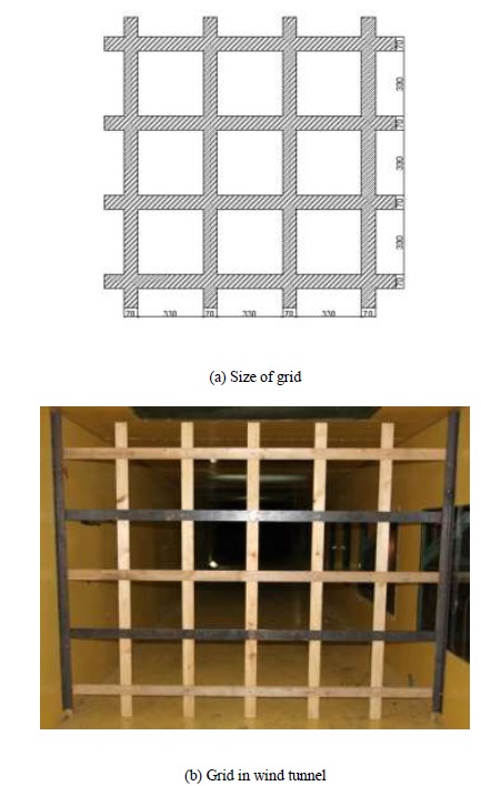
The wide-body flat steel box girder model in this paper derives from the actual project under construction Chongqing Cuntan Yangtze River bridge. The bridge consists of two side span and the main middle span with an arrangement of (250 m + 880 m + 250 m). Rise-to-span ratio of the bridge is 1/8.8 and the distance of the two parallel main cables is 39.2 m. The width and height of the girder is 42.0 m and 3.5 m, respectively. The rest of the size parameters of the standard cross-section for the main girder are shown in Fig. (1). Other ancillary structures used in the wind tunnel test are pedestrian guardrail, anti-collision guardrail, center separation band guardrail and lead rail. Two different kinds of guardrails are also included in the experiment shown in Fig. (1).
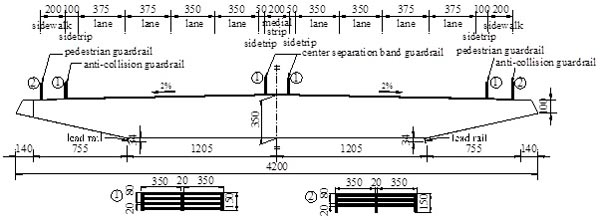
Section model of the bridge is made of light wood. Pedestrian guardrails, anti-collision guardrails and center separation band guardrails are directly manufactured by machine with plastic plates. The section model has a size of 2.1 m in length, 0.7 m in width, and 0.0583 m in height with a scale of 1/60 to the real bridge girder.
Wind tunnel test requires that the section model should be similar to the real bridge girder in geometric dimensions, as well as frequency and damping ratio. However, it is well known that the section model can’t have similarity with the prototype model in all aspects and the appropriate deviation is allowable in the wind tunnel test. The damping ratio deviation tolerance should be controlled less than 10% and the deviation of frequency, mass should be controlled within 3% [14] (Table 1). compares the related parameters between the section model and the actual girder. It can be seen that the error is 4.3% for the vertical bending damping ratio and 3.8% for the torsion damping ratio. And other parameters are all the same to those of the prototype girder. Therefore, the results of experiment are effective.
| Parameters | Units | Actual value | Value required | Value in test |
|---|---|---|---|---|
| Height | m | 3.5 | 0.0583 | 0.0583 |
| Width | m | 42.0 | 0.7 | 0.7 |
| Mass | kg/m | 27600 | 7.667 | 7.667 |
| Mass moment of inertia | kg∙m2/m | 5137700 | 0.3987 | 0.3987 |
| Vertical bending frequency | Hz | 0.17446 | 2.216 | 2.216 |
| Vertical bending damping ratio | % | 0.5 | 0.389 | 0.372 |
| Torsion frequency | Hz | 0.39726 | 5.404 | 5.404 |
| Torsion damping ratio | % | 0.5 | 0.439 | 0.422 |
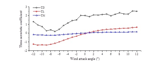
The experiment is carried out in the second test section of the industrial wind tunnel (XNJD-1) in the Southwest Jiao-tong University of China (Fig. 2a). This test section is 2.4 m wide and 2.0 m high. The maximum wind velocity is 45.0 m/s and the minimum wind velocity is 0.5 m/s. Both the turbulent flow with error less than 0.1% and uniform flow can be generated. The section model is installed in the middle of the test section filling all the test section width. As is well-known, the natural wind is turbulent and the boundary layer exists near the surface of the ground. Neglecting the effect of the boundary layer, the experiment is performed in a uniform flow. And in practice, this effect in wind tunnel is more severe than that of the actual condition because the side force under this condition is larger than that of the real [15]. Test of static force coefficients in wind tunnel is shown in Fig. (2b). And the test results are shown in Fig. (3), where the parameter CL is the lift coefficient, CD is the resistance coefficient, and CM is the pitching moment coefficient, respectively.
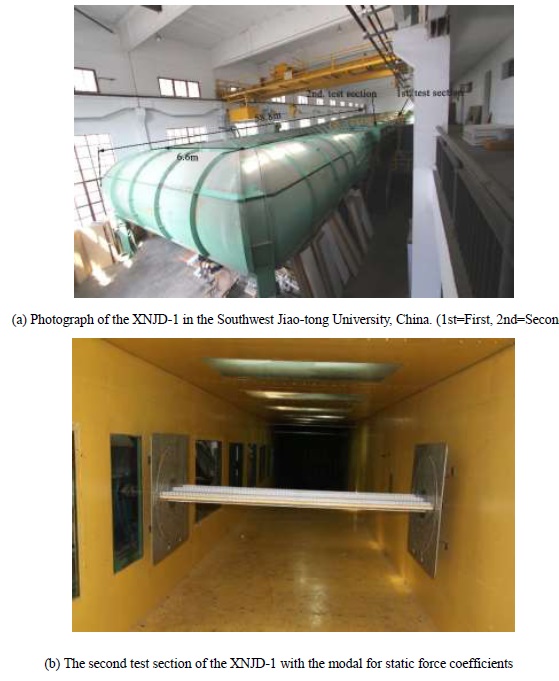
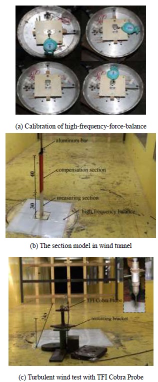
Aerodynamic admittance is measured by the high-frequency-force-balance equipment (HFFB) shown in Fig. (4a). The section model shown in Fig. (4b) is divided into two adjacent separated parts with a distance about 2 mm in the same cross section size: measuring section and compensation section. The former is installed on the HFFB at the bottom and the latter is fixed to the bracket device on the top wall of the wind tunnel. Both of them can keep synchronous rotation to change the wind angle of attack. In order to reduce the effect of boundary layer as well as three-dimensional turbulence, a rectangular plastic separation sheet is installed between the testing section model and HFFB. The section model has a scale ratio of 1/300 to the real bridge girder. The basic frequency of the section model in-plane is 56 Hz, out-of-plane 35 Hz, reverse fundamental frequency is 81 Hz. All of them are much greater than the minimum value 15 Hz recommended in [14]. And this can guarantee the aerodynamic admittance reduced frequency consistent with the actual bridge girder. HFFB is fixed on the wind tunnel floor surface. The Turbulent Flow Instrumentation (TFI) Series 100 Cobra Probe sensor shown in Fig. (4c) is used to collect the turbulent wind data with a higher accuracy than the hot wire anemometer. Three components time history curve of the turbulent wind speed are measured by the TFI Cobra Probe sensor. Three components of the power spectrum for turbulent wind can be handled by the Fast Fourier Transformation program (FFT) with Matlab. The location of TFI Cobra Probe is 2.4 m from the grid in the horizontal direction and 0.3 m from the bottom of the wind tunnel in the vertical direction. Longitudinal direction of the wind is defined as U, across direction of the wind is V and vertical direction of the wind is W. And the sampling frequency is set to 256 Hz.
3. METHOD
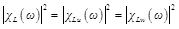
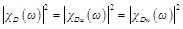
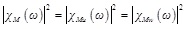
Equivalent aerodynamic admittance method is used in the study which is established on the basis of the cross power spectrum modification. Usually, assuming that different wind speed components have the same admittance to each other, three undetermined aerodynamic admittance functions are deduced. They can be expressed using the traditional single component definition based on the assumption of Equation (Eq.) (1) to (3).
 |
(1) |
 |
(2) |
 |
(3) |
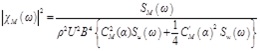
Where ω is the angular frequency of the fluctuation; χD, χDu and χDw are the three components of the resistance aerodynamic admittance; χL, χLu and χLw are the three components of lift force aerodynamic admittance; χM, χMu and χMw are the three components of pitching moment aerodynamic admittance.
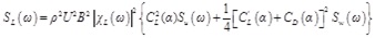
Buffeting force spectrum can be represented by Davenport model with the Time-Frequency Fourier Transformation.
 |
(4) |
 |
(5) |
 |
(6) |
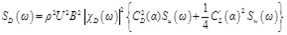
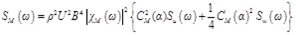
Where ρ is the density of fluid, U is the horizontal structure, B is the chord length of the bridge section, CL is the lift coefficient, CD is the resistance coefficient, CM is the pitching moment coefficient. Su and Sw are the horizontal and vertical velocity fluctuations, repsectively. α is the wind attack angle. SD, SL and SM are the resistance, lift force and pitching moment power spectrum, respectively.
Inserting Eq. (1) ~ (3) into (4) ~ (6), the buffeting force spectrum can be expressed as:
 |
(7) |
 |
(8) |
 |
(9) |
The aerodynamic admittance can be derived analogously:
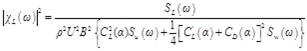 |
(10) |
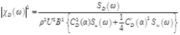 |
(11) |
 |
(12) |
4. FACTORS INFLUENCING BUFFETING FORCE SPECTRUM
The turbulent wind field is generated by the lattice grid in wind tunnel test. The width of the grid component is 7.0 cm with a center distance of 33.0 cm. The grid is installed in the entrance of the wind tunnel with a 19.5 cm distance from the top wall shown in Fig. (5). Both turbulence intensity and turbulence integral scale are calculated from the data measured by the TFI sensor. The final results are Iu=8.0%, Iw = 6.5%, Lux = 0.108m and Lwux = 0.040m, where the Ii and Lix(i = u, w) are the corresponding turbulence intensity and turbulence integral scale, respectively.
4.1. Wind Speed
FFT method is used to deal with the force time history data measured by HFFB in order to study the effect of wind speed. And the buffeting force power spectrums at the wind speed of 8.0 m/s, 10.0 m/s and 12.0 m/s are obtained (Fig. 6).
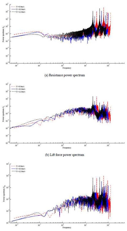
From the Fig. (6), it can be seen that the resistance, lift and pitching moment power spectrum at different wind speeds have presented the overall migration, and the resistance power spectrum has the most obvious offset. Range of three power spectrum frequency becomes low as the wind speed increases. Resistance power spectrum numerical value decreases with the trend of wind speed at low frequency while increased at high frequency. Lift and pitching moment power spectrum increase with the trend of wind speed at the whole range of frequency.
4.2. Wind Attack Angle
In order to study the effect of wind attack angle, force time history curves measured by HFFB are dealt with the FFT method, and the buffeting force power spectrums at -3°, 0° and +3° wind attack angle are obtained and shown in Fig. (7).
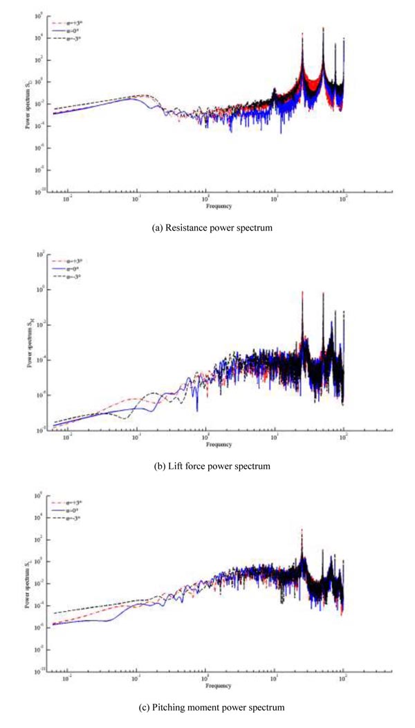
It can be seen from the Fig. (7) that the resistance, lift and pitching moment power spectrum at different wind attack angles almost do not change all over the range of frequency. Therefore, the wind attack angle has little or no effect on the frequency range of buffeting force power spectrum. Quantitatively, the resistance power spectrum numerical value is affected mostly by the wind attack angle in buffeting force of power spectrum, the smallest numerical value of which is in the wind attack angle of 0° and keeps almost the same of that at -3° and +3°.
5. FACTORS INFLUENCING AERODYNAMIC ADMITTANCE
5.1. Wind Speed
In order to study the effect of wind speed, buffeting force power spectrum is calculated with the equivalent aerodynamic admittance recognition method. And the aerodynamic admittances at 8.0 m/s, 10.0 m/s and 12.0 m/s wind speed are obtained and shown in Fig. (8).
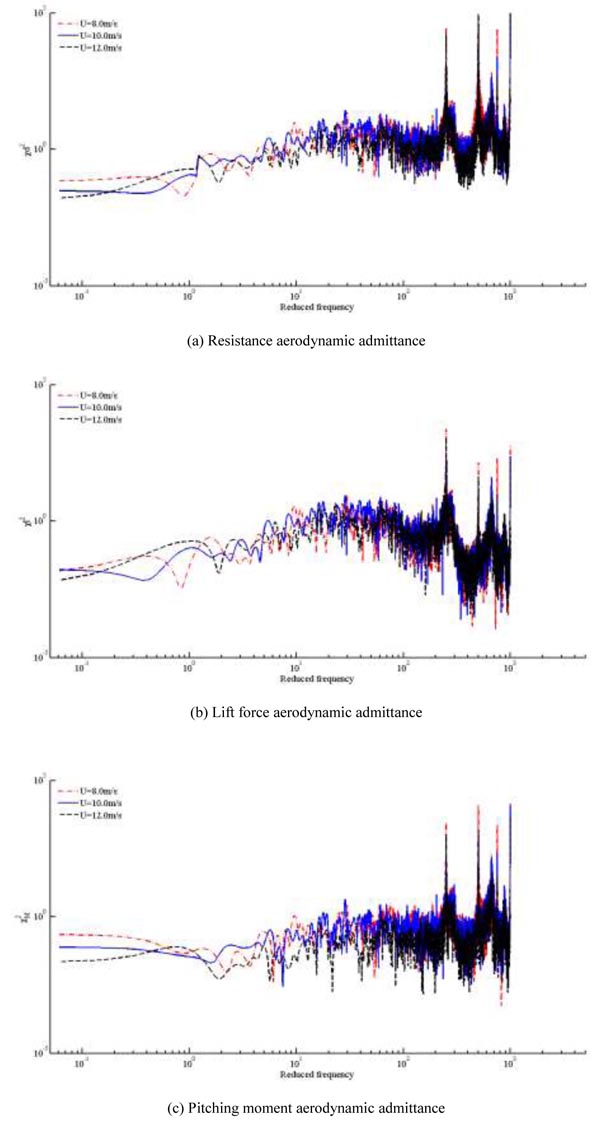
From the Fig. (8), it can be seen that all of the aerodynamic admittance values decrease with the trend of the wind speed. And the pitching moment aerodynamic admittance is of most sensitive among three aerodynamic admittances. The following is the resistance aerodynamic admittance with the lift force aerodynamic admittance dull. Aerodynamic admittance value at low frequency variation is more obvious than that of the high frequency.
5.2. Wind Attack Angle
In order to study the effect of wind attack angle, buffeting force power spectrum is calculated with the equivalent aerodynamic admittance recognition method, and the aerodynamic admittances at -3°, 0° and +3° wind attack angle are obtained and shown in Fig. (9).
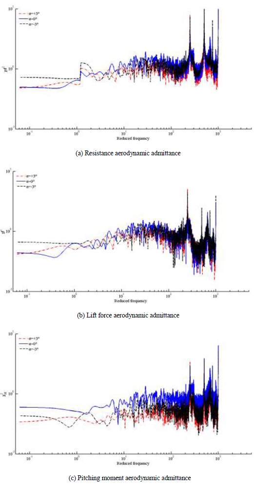
From the Fig. (9), it can be seen that nearly no change of the resistance, lift and pitching moment aerodynamic admittance at different wind attack angles takes place at the whole range of the reduced frequency. Therefore, wind attack angle has no effect on the reduced frequency range of aerodynamic admittance. The aerodynamic admittance value keeps almost the same at -3° and +3° wind attack angle at high reduced frequency with the value at -3° higher than that of +3° at low reduced frequency. The resistance and pitching moment aerodynamic admittance value at 0° wind attack angle are slight higher than that of -3° and +3°. Pitching moment aerodynamic admittance is obviously higher than that of -3° and +3°.
6. AERODYNAMIC ADMITTANCE EXPRESSION
Aerodynamic admittance has great influence on buffeting response. In order to get a more accurate bridge buffeting response, aerodynamic admittance expression of wide-body flat steel box girder is presented in this paper by custom equation in Matlab with Eq. (13).
 |
(13) |
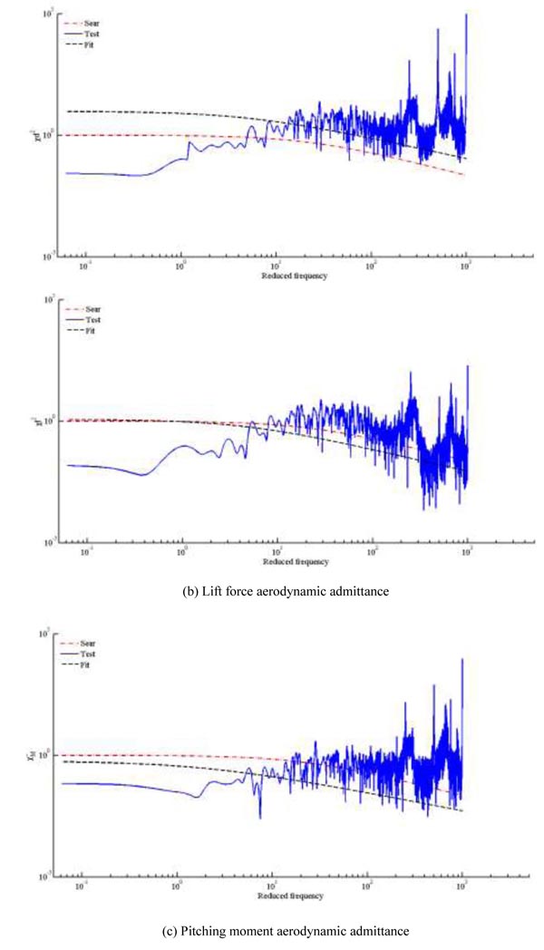
Conservative structural design is widely applied in engineering. Therefore, the most demanding conditions of the 12.0 m/s wind speed and 0° wind attack angle are chosen to fit the aerodynamic admittance function in three different directions. The corresponding test results, Sear expression and the fitting expression are shown in Fig. (10).
Aerodynamic admittance expressions of resistance, lift force and pitching moment are deduced finally in Eq. (14) to (16).
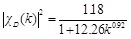 |
(14) |
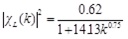 |
(15) |
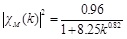 |
(16) |
From Fig. (10), it can be seen that the fitting aerodynamic admittance expressions are more close to the test results than the Sears expression. Therefore, when analyzing the buffeting response of wide-body flat steel box girder in this paper, the fitting aerodynamic admittance expressions can get more accurate response of the bridge than the Sears expression.
CONCLUSION
Aerodynamic admittance is measured with HFFB by the method of equivalent aerodynamic admittance recognition in this paper. The effect of wind speed and wind attack angle to wide-body flat steel box girder is studied at different working conditions. Conclusions can be illustrated as follows:
- Aerodynamic admittance value decreases with the trend of wind speed. And for wind speed influence, the pitching moment aerodynamic admittance is of the most sensitive among the three aerodynamic admittances, followed by the resistance aerodynamic admittance with the lift force aerodynamic admittance dull. Aerodynamic admittance value variation at low frequency is more obvious than that of high frequency.
- Lift and pitching moment aerodynamic admittance at different wind attack angles nearly have no variation all over the range of reduced frequency. The aerodynamic admittance values at -3° and +3° wind attack angle keep almost the same at high reduced frequency with the value at -3° higher than that of +3° at low reduced frequency. The resistance and pitching moment aerodynamic admittance value at 0° wind attack angle are little higher than that at -3° and +3°. Pitching moment aerodynamic admittance is obviously higher at -3° and +3°, respectively.
- Compared with the wind attack angle, the influence effect of the wind speed for the aerodynamic admittance is more apparent. Aerodynamic admittance variations of the wide-body flat steel box girder under different wind attack angles can be neglected.
- The measured aerodynamic admittance function of the wide-body flat steel box girder is extremely inconsistent with the classical Sears expression. Aerodynamic admittance expressions deduced from the experimental data in this paper are more credible and suitable for the actual bridge buffeting response analysis.
CONFLICT OF INTEREST
The authors confirm that this article content has no conflict of interest.
ACKNOWLEDGEMENTS
This work was funded by Natural Science Foundation of China (NO.51578098), science and technology project of Chongqing Municipal Construction Commission (NO.20130844), and they are gratefully acknowledged.

