All published articles of this journal are available on ScienceDirect.

Cultural Heritage and Earthquake: The Case Study of “Santa Maria Della Carità” in Ascoli Piceno
Authors Info & Affiliations
Abstract
Background:
In October 2016, two major earthquakes occurred in Marche region in the Centre of Italy, that resulted in widespread damage. The second one strokes Norcia, Visso, Arquata del Tronto, Accumoli and Amatrice, causing a lot of damages to cultural heritage of the cities of Tolentino, San Severino, Camerino and Ascoli Piceno, where the church of Santa Maria della Carità is located.
Introduction:
The church has high historical, architectural and social value for the city of Ascoli Piceno, because it is the only one that is opened to the devotees all time in the day and night. From the structural point of view, the church has a long and important annex to the north, which was later built with respect to the church, and after the L’Aquila earthquakes (2009) damages, the church was subjected to a retrofit intervention, in order to obtain a better “box-like behavior”.
Objective:
This paper addresses how the relevant annex influenced the seismic response of this historical complex and how, more generally, this kind of asymmetric mass may affect the behavior of historic churches.
Results and Conclusion:
The results indicate that the presence of annex plays a significant role in the dynamic response of the church and affects the distribution of damages in the whole building. The results of the seismic simulation agree with the observed damage.
1. INTRODUCTION
The vulnerability assessment of historical constructions against seismic actions, which is the necessary pre-requisite for their continuous protection, is of strategic importance considering the richness of the European and Italian architectural heritage [1, 2].
Churches are usually characterised by a high seismic vulnerability due to their structural and geometric configurations, heterogeneous and deteriorated materials. These structures have very large and high external walls without internal orthogonal walls: the space thus created is often covered by some thin vaults or thrusting arches. Furthermore, the structural portions (i.e., macro-elements) present an autonomous dynamic behavior mainly caused by the lack of a rigid intermediate horizontal diaphragm and a lack of walls interlocking. For this reason, historic churches often show the absence of box-like behavior.
In the last century, the seismic events stroked the historic cultural heritage severely and in particular, 49% of the damaged structures were of the churches highlighting their intrinsic vulnerability [3-7]. The recent earthquakes that hit Italy in August and October 2016 confirmed the high vulnerability of this type of structures. Tuned with this issue, it becomes necessary to take a census of the flaws in these monuments through the structural identification procedures and the evaluation of the related ground motion characteristics [8, 9].
These particular monumental buildings cannot be reduced to any standard structural scheme, and this makes it difficult to evaluate their seismic reliability. To overcome this problem, the macro-element approach was proposed a few years ago and has been repeatedly used to recognize the collapsed mechanisms in the different macro-elements of the church. The typical collapsing configurations are shown in Italian Guidelines for the Cultural Heritage [10].
The formation of Italian historical centres is often the result of uncontrolled constructive evolution; in particular, this complex configuration of the centres leads the structures to strongly interact with one another when they are subjected to seismic action [11-15]. As a matter of fact, several historic churches are not isolated from the urban context, but, adjacent buildings, usually named annexes (convents, sacristy, tower, minor constructions, etc.) built at the same time of the church or subsequently added as shown in other case studies [16, 17].
To determine the construction phases of the church and of the annexes, the first operation to perform is the historical analysis of the building evolution, crucial is also the study of the documentations of the structural interventions [18]. There could be, for example, interventions that made a structure more stiffened with respect to the other.
In addition to the churches that belong to the aggregates in the historic centres [19], the cases of incorporated churches, present in all over the world, are typical of different types of monasteries [20]. As a matter of fact, these amazing complex structures are the clearest and spread example of churches affected by the presence of the annexes. These other buildings can affect the church (in width and height) partially or fully incorporate it.
This paper presents the case study of Santa Maria della Carità church, firstly hit by L’Aquila earthquake (on April 6, 2009) with a magnitude MW=6.3. After this seismic event, the church was closed because several cracks appeared; in particular the main vault and the triumphal arch were the elements mainly damaged, and for this reason, retrofitting was done in 2010. The church was successively re-closed, as a precaution, in August 2016 due to the Marche-Umbria-Lazio-Abruzzo earthquakes, that presented an epicentre nearest to the church with respect to L’Aquila earthquake. Up to this moment, the earthquake of October 30th, 2016, with a magnitude of 6.1 ML and 6.5 MW, was the strongest event of the sequence which began with the earthquake of August 24th of MW=6.0 and also counted a quake of magnitude MW=5.9 on October 26th. At the present time, the church presents only some damages on the stuccos and on the vault of the presbytery, but the question of how important annex had engraved on the dynamic-behavior during the earthquake arise from the observation of an unsymmetrical damage survey.
In this work, the influence of all parameters involved in the local and global structural response was evaluated, such as the annex, the floors stiffness (diaphragm effect), and the retrofitting works done in 2010. To this purpose, the use of advanced numerical tools to perform nonlinear three-dimensional (3D) analyses is necessary in order to investigate all the possible failure mechanisms, both local and global, of a masonry structure, when this is subjected to an earthquake. The complexity of this type of analysis is required to validate the implemented model accurately; differently, a sensitivity analysis is mandatory to reduce the variability of the structural response, or better to avoid unclear situations from a structural point of view as much as possible.
The estimation of the beneficial effects of the retrofitting actions is even more accurate, since such evaluation is based on the difference between the seismic vulnerability of the structure in the current state and in the restored one [21, 22], both of them analysed with the same Finite Element Model (FEM). For these reasons, in this work, eight different FEMs were studied in order to establish the significant deficiencies of the structure, and to capture the influence of all parameters involved in the structural seismic response. Moreover, the estimation of the beneficial effects of the proposed restoration actions is even more accurate and can be helpful to the designers in other case studies.
2. HISTORICAL DEVELOPMENT AND SURVEY OF THE CASE STUDY
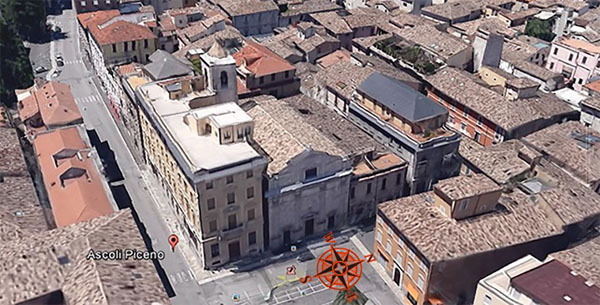
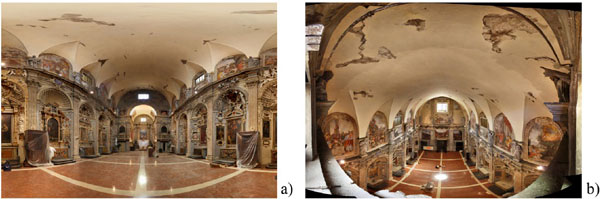
The church of Santa Maria della Carità in Ascoli Piceno has a significant historical and architectural value: it is one of the most prominent examples of the Barocco age in Marche Region and contains a lot of valuable paintings of local artists. Moreover, it has also a social value for the city of Ascoli Piceno (see Fig. 1), as it is the only one opened to the devotees all day and night long [23].
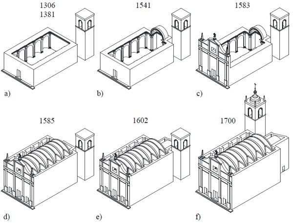
The period of its construction is unknown, but the first proof of the existence of a little church, dating back to 1306, can be found in a parchment. On the Northside of the Church, there is an annex that was built in 1196 and that hosted a hospital; this hospital, in particular, was managed by the same fraternity that took care of the church. The old church was very different from the actual one (2a-2b). Later, from the early years of the 16th century up to 1583, the building was partially demolished and re-built in various phases and in the same place, with the modification of the facade by raising the tympanum and by opening the doors on the front facade Fig. (2c). Further to this intervention, the nave was covered with a masonry vault and connected to the apse through a triumphal arch. Therefore, iconographical documents attest the presence of a pre-existing bell-tower on the opposite side by comparison to the actual one Figs. (2d-2e). So the triumphal arch was built during the 16th century, but the actual bell-tower was built only at the end of the 17th century, after almost one hundred years (Fig. 2f) [24, 25].
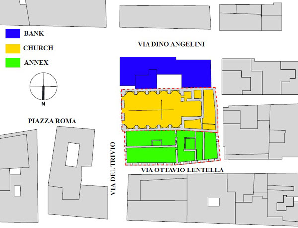
Between 1930 and 1932 Fig. (3) the south allay of the church was closed after the edification of a building that features a concrete frame that is totally disconnected to the church. This very building now hosts a bank.
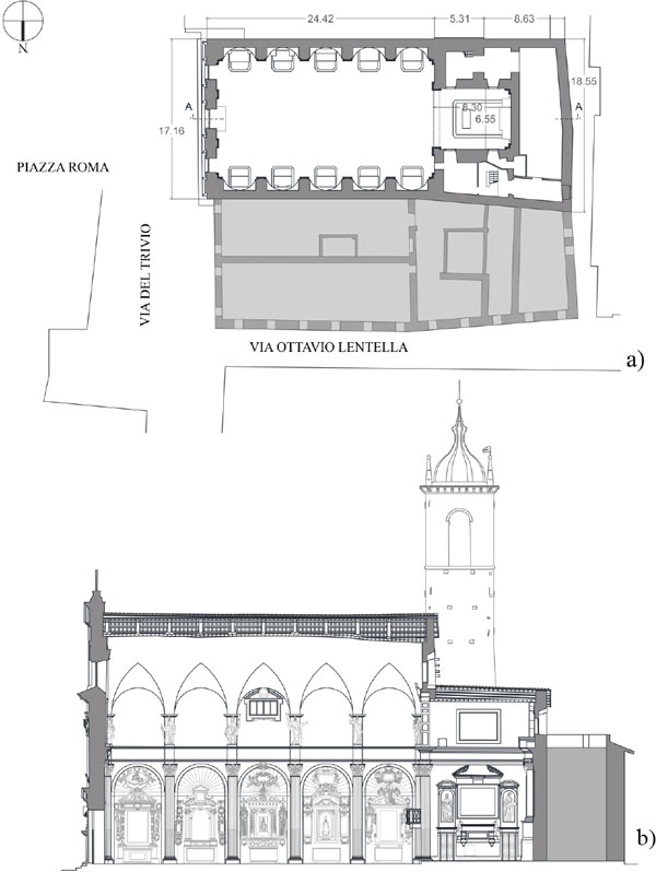
The church has a unique nave of 12.93 m wide, 23.15 m long and has a maximum height of 16.5 m; it ends with a rectangular apse of 6.55 m wide, 8.30 m long and with a height of 11.95 m Fig. (4). The apse is inside the sacristy, that counts two floors and has a maximum height of 15.90 m. In the sacristy, there is also the bell-tower: it has a square shape with side of 4.31 m and a maximum height of 27.80 m. The thickness of the walls ranges between 2.21 m (the piers of the nave) and 0.91 m (the walls of the nave). The bearing structure is made of stone masonry; the main façade, characterized by three front doors, has ornaments with classical patterns (columns, tympanum, cornice) and the masonry layer is constituted by white travertine; the nave is covered by a brick elliptic vault (like the apse zone) with lunettes that create small ornamented niches that are joint to the internal columns. Also in Santa Maria della Carità, like many other Italian churches, the triumphal arch separates the nave area from the apse. The arch is inserted in a masonry panel, with an elliptically shaped opening that is about 1.2 m thick.
The church walls present different masonry materials (i.e., brick, travertine, stone, etc.); in the walls of the nave there are two distinct types of masonry in the elevation: this can be explained by the different age of edification. At a height of 11.08 m there is travertine block, and up there is an irregular stone.
In the past, the annex (on the North side of the church, Fig. (3) was a hospital, while now it hosts shops and a private house. The annex has a rectangular plant of 13.10 m of maximum width, 36.80 m length and a height of 12.40 m, and it features an arcade that is visible thanks to the presence of cross vaults in the centre zone. The period of its construction is unclear. Nowadays a lot of shops and private houses are contained in this part of the aggregated buildings.
3. THE EARTHQUAKE DAMAGE AND FIRST PROVISIONS
After L’Aquila earthquake in 2009, the church was closed due to several cracks on the triumphal arch (Fig. 5) and on the vault of the nave. Other damages were visible in the non-structural elements inside the church. Moreover, a possible activation of the overturning mechanism of the facade was observed; in fact, there were cracks on the connection with the vault.
In order to put the church back into service as fast as possible, interventions were designed and executed in 2010. Concerning this issue, it becomes necessary to investigate the weakness of this monument through the analysis of the possible local collapse of the macro-element, the material and damage survey, the structural identification procedures and the subsoil–structure interaction.
To perform a local analysis, it is common to subdivide the structure into macro-elements, that consist of sub-structures characterised by their own seismic behavior, almost independent from the rest of the structure (façade, apse, dome, bell tower, etc.). For each macro-element, one or more damage modes and the associated collapse mechanisms can be identified. Such approach is mainly based on the a priori-assumption of a set of failure mechanisms, identified through the experience of previous seismic events. They are reported for example in [10], and they represent the most diffused partial collapses occurring in real churches/monasteries which fell after recent earthquakes.
For the Santa Maria della Carità church, the linear kinematic procedure was implemented in order to analyse the possible activation chosen from the twenty-eight failure mechanisms contained in [10]. Actually, the following overturning mechanisms depicted in Fig. (6), can be activated:
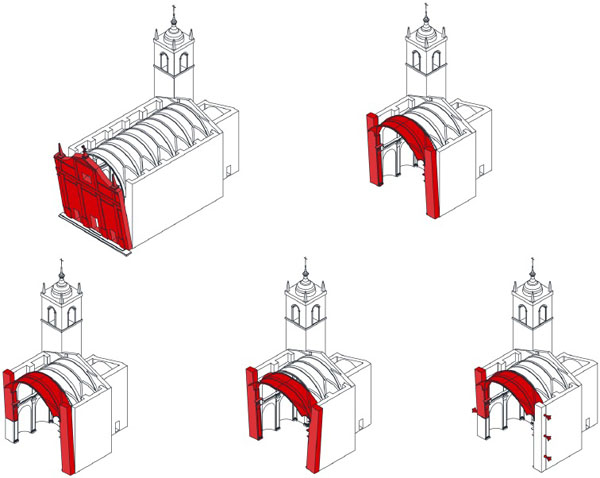
- Out-of-plane overturning mechanism of the facade;
- Out-of-plane overturning mechanism of the wall of the nave;
- In-plane damage mechanism of the vault of the nave.
The acceleration of the activation of the mechanism has been computed by following the Italian standards [26, 27]. To prevent the activation of these mechanisms, some interventions have been designed.
The masonry was not completely visible, and for this reason, a lot of surveys were performed (Fig. 7), in order to accurately recognize the masonry type and to confirm the wall thickness. To complete some missing data from in-situ tests, the Italian Codes for existing masonry buildings [26, 27] have been consulted.

| fc | ft | γ | E | ν | Gc | Gf | Confidence Factor (CF) | |
|---|---|---|---|---|---|---|---|---|
| [MPa] | [MPa] | [N/mm3] | [MPa] | [N/mm] | [N/mm] | |||
| Squared block stone masonry thin joins – Material 1 | ||||||||
| KL1 | 5.33 | 0.53 | 0.000022 | 3840 | 0.3 | 3.74 | 0.04 | 1.35 |
| Squared block stone masonry – Material 2 | ||||||||
| KL1 | 4.44 | 0.44 | 0.000022 | 2800 | 0.3 | 3.29 | 0.03 | 1.35 |
| Stone and solid bricks masonry – Material 3 | ||||||||
| KL1 | 3.11 | 0.31 | 0.00002 | 2150 | 0.3 | 2.56 | 0.03 | 1.35 |
| Solid bricks and lime mortar masonry good mortar – Material 4 | ||||||||
| KL1 | 2.67 | 0.27 | 0.000018 | 2250 | 0.3 | 2.30 | 0.02 | 1.35 |
| Disordered rubble stone masonry –Material 5 | ||||||||
| KL1 | 0.74 | 0.07 | 0.000019 | 870 | 0.3 | 0.94 | 0.01 | 1.35 |
| Solid blocks and disordered rubble stone masonry– Material 6 | ||||||||
| KL1 | 1.25 | 0.12 | 0.0000194 | 1677 | 0.3 | 1.35 | 0.01 | 1.35 |
| Squared block stone and disordered rubble stone masonry thin joins – Material 7 | ||||||||
| KL1 | 1.24 | 0.12 | 0.00002 | 2202 | 0.3 | 1.35 | 0.01 | 1.35 |
The low level of knowledge obtained (KL1) for this case study has led to assume the highest confidence factor (FC) equal to 1.35, and so the compression strength was reduced by this factor. The masonry tensile strength was considered equal to 10% of the compressive strength [20]. The main mechanical characteristics used in the sequel, are shown in Table 1.
3.1. The 2010 Retrofitting Intervention
The extent and nature of the actions must then be balanced between the conflicting requirements of achieving a newly required safety level and regarding the original conception and historical value. However, it must be noticed that in some cases, the strict application of this approach may lead to erroneously accept higher risks to avoid or limit works that are recommended from a structural point of view, see e.g [28]. The philosophy followed in the restoration process tends to prefer measures that comply with the concepts of reversibility, recognisability, minimum impact and compatibility of the intervention with the existing structure, considering the possibility that in the future, a better intervention could be carried out, as a result of more accurate studies or the evolution of technologies.
The results of the limit analysis of the macro-elements showed that at that moment, the primary structural deficiencies were: (1) the lack of connection of the front façade to the rest of the structure and (2) the high-stress level of the upper part of the nave masonry walls subjected to the static load of the central vault. Therefore, the restoration actions should affect the entire structure of the church to restore a “box-like behavior”, that is able to transfer the horizontal actions to all the bearing walls and should consider the possibility of increasing the material resistance in the most stressed regions. However, to pursue this latter effect, it would be necessary to implement actions which are in contrast with the concept of reversibility of the intervention and therefore, care is needed at this stage.
Generally, a rigid diaphragm behavior can be achieved by operating both at the intrados (e.g., with metal rods, steel elements, and other reinforcement systems) or at the extrados by implementing a timber panel over and/or substituting the original one, inserting metal rods into the top light concrete layer or metal plates - to be fixed to the wood beams - or adding a new reinforced concrete thin slab securely connected to the walls. Interventions at the extrados present the advantage of being less invasive, since they are hidden in the floor and do not alter the architectural identity of the building. In order not to affect the view of the time, it was decided not to insert steel chains in the intrados.
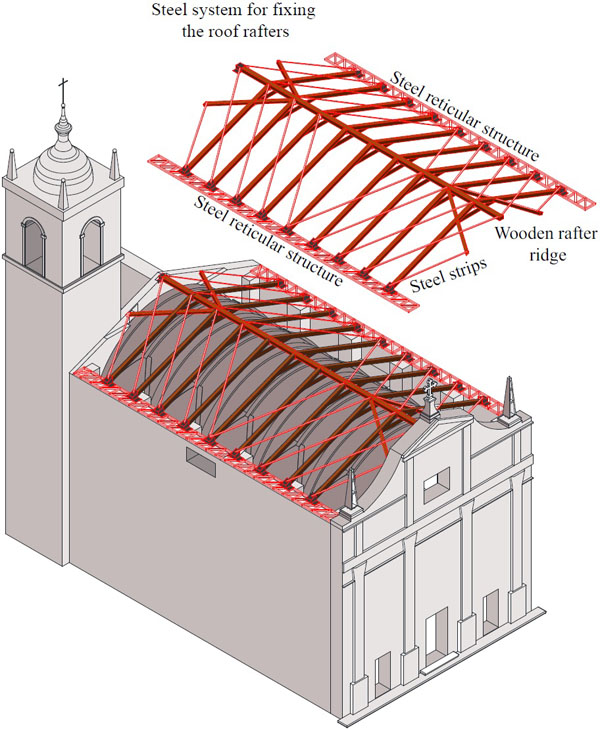
Hence, it has been suggested that the roof slabs should be stiffened in their plane in order to be considered as rigid diaphragms and new timber beams, replacing the deteriorated existing ones, should be anchored to the bearing walls. The interventions consisted of making a reticular beam system on the plan of a pitched roof. The reticular beam system is composed of metal bands that act as strings, wood stands that serve as rafter, ridgepole, and framework curb, which serve respectively as (higher) tense and (lower) compressed truss (Fig. 8).
In its current state, the connections to the vertical structural elements rely exclusively on friction between them. Such connection improvement was achieved using a further reticular system (Fig. 8) fixed with bars to the top of the nave walls - in order to limit the out-of-plane movements and featuring anchored plates - of various types - directly anchored to the nave walls. Other connections should also be established between the beams and the façade; the beams have a support constraint so as to eliminate the horizontal force on the façade, force that acts only as a return to rollover. In a study [23], structural details and pictures of the realised retrofitting intervention are reported.
The retrofitting system is able to (i) contrast the out-of-plan collapse of façade, (ii) contrast out-of-plan collapse of the tympanum on the triumph arch, (iii) balance the thrust of the vault on the walls nave, (iv) stiffen the gabled roof. The post intervention is evaluated, again, with the linear kinematic analysis. This intervention permits to verify all the mechanisms. In order to limit the cracking on the nave vault, and on the triumph arch, carbon FRP strips were inserted to the extrados of these elements.
It is necessary, however, to consider that this approach presents the risk of exceeding the estimation of the collapsing horizontal acceleration. Furthermore, with this method it is impossible to quantify the effect of the retrofitting on the global response. For this reason, it is indispensable to contemplate additional methods of analysis, for example the 3D Finite Element Analysis procedure that has been recently applied to many churches, tower and monasteries in seismic areas [2, 29, 30].
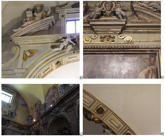
After the seismic event in October 30th, only a few cracks have appeared on the stuccos of the triumphal arch and of the walls of the nave (Fig. 9a and 9b), confirming that the main mechanisms (as pointed out in chapter 3) did not activate as in the previous seismic event in 2009, consequently, this represents the first in-situ test of the intervention. The recurring observable damage (see Figs. 5b and 9c) between the two earthquakes is the horizontal cracking on the lunette near the façade. Differently, new micro-cracking appears on the vault of the presbytery near the triumphal arch (Fig. 9d).
However, to have a better perception of the influence of the retrofitting of the roof, a global analysis should be done with and without the annex, and at varying of the floor stiffness.
4. MATERIAL AND METHODS
In this work, the nonlinear damage behavior of the masonry is considered within a continuum mechanics theory, based on a smeared crack approach [31, 32] where the cracks are not described one by one but are continuously spread within the body and affect (reduce) the medium stiffness instead.
The smeared crack concept itself offers a variety of possibilities, ranging from fixed single to fixed multi-directional and rotating crack approaches. Here, the distinction lies in the orientation of the crack, which is either kept constant, updated in a stepwise manner or updated continuously [33]. The smeared crack models are practice-oriented, due to the limited data required [34]. For example, in the context of macro-modelling, [35] adopted a smeared crack model for the simulation of brick masonry and adobe walls, and [36] used the isotropic rotating crack model to simulate panels with vertically perforated clay units and various types of head and bed joints.
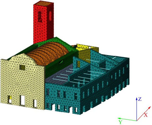
The panels were modelled with solid tetrahedron elements with 4 nodes [37], and optimised regular mesh (see Fig. 10) was used for discretization. The nonlinear behavior of the masonry panels of the historical complex is represented by a Total Strain Crack Model based on fixed stress–strain law concepts available in Midas FEA©. In this way, the cracks are fixed in the direction of the principal strain vectors that remain unchanged during the loading of the structure.
The compression behavior of the masonry was modelled by a constitutive law comprising a parabolic hardening rule and a parabolic softening branch after the peak of resistance Fig. (11a); the tension behavior was characterised by a linear hardening branch followed by a nonlinear softening branch Fig. (11b). The fracture energies in compression (Gc) and tension (Gf) are reported in Table 1, and h is the mean dimension of the mesh Fig. (10).

The shear retention factor (β) gives the shear stiffness after cracking, which can be a constant (low) value between 0 and 1, or a value depending on the crack opening. Here, a constant value equal to 0.05 was adopted like requested in [31, 38].
4.1. Finite Element Model For the Global Response
Numerical Models (NMs) built to reproduce the geometry of the structures, focusing on the variations in the wall thickness, on geometrical and structural irregularities, and on wall connections [39]. The brick-vault has been connected to the walls nave by fixed constraints since it has been built at the same time. Finally, the major openings in the buildings have been reproduced. Two are the main models used: a model pre-intervention and post intervention model.
The construction of the undamaged FE model of the church and the annex (C+A) was fundamental to study the dynamic and seismic behavior. As previously said, the annex could have been built later than the church; this hypothesis is taken into consideration in an additional FE model (C) with the inclusion of a complete separation between the church and the annex. In fact, with a complete separation, it is possible to face one of the main problems of the historic masonry buildings, that is the materials deterioration - particularly of the mortars - that can affect the real partial interaction. The reason for the degradation of this part is often due to the low quality of the conservation and other exceptional events or new additional loads.
Furthermore, a proper assumption on the diaphragm stiffness may significantly affect the overall response [20]. In fact, in the limit case of “infinitely” flexible floors, there would be no load transfer from heavily damaged walls to still efficient structural elements. On the contrary, in the other limit case of floors assumed as “infinitely” stiff, this contribution could be overestimated. Although this represents a crucial feature to be considered, the floor behavior in 3D modelling is frequently assumed (with a rough approximation) as completely rigid. This hypothesis may be unrealistic in case of existing buildings (e.g. historical masonry structures), where various ancient constructive technologies (i.e. timber floors and roofs, structural brick or stone vaults) had been used for floor and roofing systems; moreover, this is also a major issue in new masonry buildings with wooden floors and roofs.
To analyse the effect of the diaphragm stiffness on the global capacity, two different situations were then considered: (i) all floors deformable (C+A+D) and (A+D), and (ii) all floors rigid in their plane (C+A+R) and (A+R). To have a complete characterisation of the case study, a full implement of the strengthening provision was done, finally obtaining:
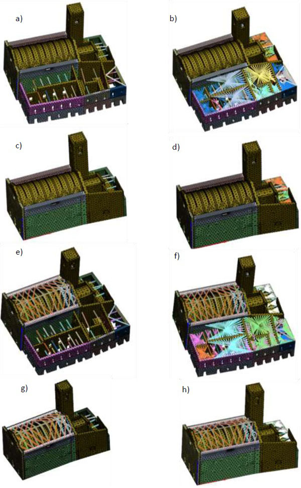
- The Church and the Annex with Deformable floors Without Intervention (C+A+D+Wi) – Fig. (12a).
- The Church and the Annex with Rigid floors Without Intervention (C+A+R+Wi) – Fig. (12b).
- The Church with Deformable floors Without Intervention (C+D+Wi) – Fig. (12c).
- The Church with Rigid floors Without Intervention (C+R+Wi) – Fig. (12d).
- The Church and the Annex with Deformable floors Post-Intervention (C+A+D+P) – Fig. (12e)
- The Church and the Annex with Rigid floors Post-Intervention (C+A+R+P) – Fig. (12f)
- The Church with Deformable floors Post-Intervention (C+D+P) – Fig. (12g)
- The Church with Rigid floors Post-intervention (C+R+P) – Fig. (12h)
After meshing, the final 3D NMs are shown in Fig. (12) and the main characteristics of the mesh regarding nodes, the number of solid elements and the degrees of freedom (d.o.f.) are shown in Table 2.
| Nodes | Solid elements | Degree of freedom | |
|---|---|---|---|
| Model 1 | 21819 | 74623 | 62970 |
| Model 2 | 21866 | 74623 | 60456 |
| Model 3 | 16672 | 58698 | 48450 |
| Model 4 | 16719 | 58698 | 47925 |
| Model 5 | 22236 | 75557 | 64347 |
| Model 6 | 22282 | 75557 | 61821 |
| Model 7 | 17136 | 59632 | 49827 |
| Model 8 | 17136 | 59632 | 49284 |
Nonlinear static analyses (i.e., pushover) are shown in the next sections and have been performed assuming a rigid ground foundation (fixed base model), and the following parameters have been adopted during the analyses:
- Maximum number of iterations of load increment: 200;
- Maximum analysis number of sub-steps: 1500;
- Minimum analysis number of sub-steps: 5;
- Initial load factor 0.01.
The nonlinear system of the equations has been solved by an incremental nonlinear static analysis with the Arc -length iteration procedure and the Initial Stiffness Method: an energy norm with a tolerance of 10-2 was required. To simulate the hypothesis of rigid floors, rigid links have been inserted in correspondence of the floors.
5. GLOBAL SEISMIC BEHAVIOR
5.1. Modal Analysis
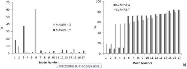
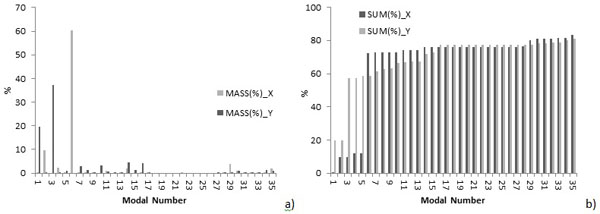
The 3D NMs have been used, in first place, to assess the (linear) dynamic behavior of the eight chosen configurations of Church and Annex. To calculate the modal shapes, considering the large number of d.o.f., the Block Lanczos method has been used. Generally, the first 50 modal shapes for all the models have been evaluated with the aim to assure that the total effective modal mass activated is at least 80% (Table 3) of the total. The main modes for the eight models are shown in Fig. (13).
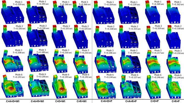
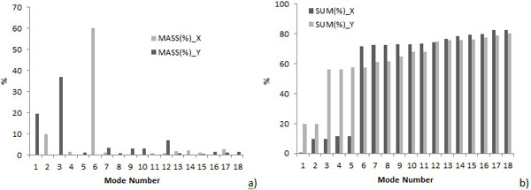
In the NMs without interventions, namely (C+A+D+Wi) (C+A+R+Wi) (C+D+Wi) (C+R+Wi), the effective and cumulative masses of each vibration modes, in the gable (transversal) and in the main nave wall (longitudinal) directions, are reported in Figs. (14, 15, 16, and 17). In all cases, the 1st and 2nd modal shapes are associated to the bell-tower, and this confirms that the tower is the most vulnerable element of the structure. For all the models, the main modal forms are the 3rd, for the transversal direction, the 6thand the 4th, for the longitudinal direction, and they are respectively associated to the out-of-plane of the walls of the nave and of the gable.


Observing the outcomes of the mode shapes resulting from the analysis component is interesting to observe the back wall of the apse and the façade: in the model (C+A+R+Wi) these walls have a completely different behavior from the configurations without the annex (C+R+Wi) which show the out-of-plane displacement and also a shift in the plane due to the additional lateral mass (Fig. 13).
In the NMs where the intervention on the roof of the church is implemented, namely (C+A+D+P) (C+A+R+P) (C+D+P) (C+R+P), in order to have the 80% of the excited modal masses, more frequencies than the previous cases should be considered, due to the presence of local mode in the roof beams.
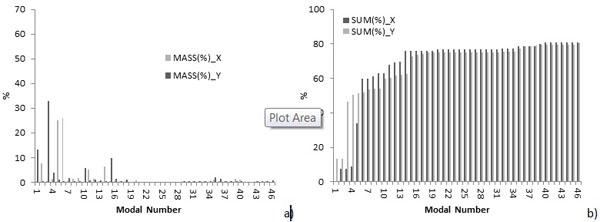
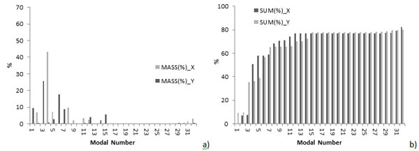
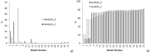
In these NMs the main mode shapes are associated with low modal mass (Figs. 18-21), due to the roof beams. Also in these NMs, the 1st and 2nd modal shapes are connected to the bell-tower. As in the case of pre-interventions, the subsequent (main) shapes are associated with out-of-plane movements of the nave walls and of the gable (the 3rd for Y-direction, the 4th and 6th for X-direction).
The presence of the intervention on the roof of the church reduces the deformation of the wall adjacent to the annex. In fact, observing the different modal shapes of (C+A+D+Wi), the church and the annex with deformable floors in a pre-intervention phase, and (C+A+D+P), the church and the annex with deformable floors in a post-intervention phase, it is possible to see that the interventions reduce the deformation of the main nave walls but also of the gable. Taking into account the model of the church with the annex and the model of the only church Fig. (13) it is possible to see, as expected, that the annex reduces the deformation of the church walls in the North direction. The observation of the frequencies shows that in the post-intervention phase, for the first and second modes, these are generally lower than in the pre-intervention, but the increment of the number of the analysed modal shapes results in higher frequencies in comparison with the pre-intervention ones.
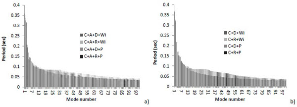
In Fig. (22) the first 100 frequencies are reported to compare the different dynamic behavior in the presence and in the absence either of the annex and the retrofitting. The main conclusion is that the presence of the annex reduces the period of oscillation; differently, the retrofitting of the roof limits the out-of-plane deformation of the walls of the nave that occurs out of the geometric plan of the walls but the period is quite invariant with respect to the previous case, confirming the non-invasiveness of the retrofitting intervention.
5.2. Seismic Demand
The considered building belongs to the “Class II” according to the Italian seismic code [26]. The Limit State of Significant Damage (SLSD [40], or SLV in Italian) has a recurrence period (TR,D) of 475 years, which corresponds to an expected Peak Ground Acceleration (PGA) equal to 0.156g. The parameters that characterise the elastic response spectrum and the PGA are (soil type T1 and category of subsoil A are considered): S = 1.49; TB = 0.168 s; TC = 0.504 s; TD = 2.18 s.
5.3. Nonlinear Static Analysis: Preliminary Considerations
The seismic behavior has been analysed by using a nonlinear static analysis method: under conditions of constant gravity loads, monotonically increasing horizontal loads have been applied [41]. Based on this method, the effects of the seismic loads have been evaluated by applying two systems of horizontal forces perpendicular to one another and not acting simultaneously. The first load distribution was directly proportional to the masses of the structures (PushMass) on each floor; the second load distribution was proportional to the main mode in the considered direction (PushMode). These two load distributions could be considered as two limit states of the building capacity.
It is noteworthy to point out that a conventional pushover is assumed in the study, i.e. loads applied to the building do not change with the progressive degradation of the structure that occurs during the loading. This means that the conventional pushover does not account for the progressive changes in the modal frequencies due to yielding and cracking on the structure during the loading [42]. Hence, the hypothesis of invariance of static loads could cause an overestimation in the analysis of the masonry building seismic capacity, especially when a non-uniform damage on the buildings or a high level of cracking are expected. However, also in its conventional form, the pushover provides an efficient alternative to expensive computational nonlinear dynamic analyses and can nevertheless offer useful and effective information on the damage state that the building can develop under seismic loads [43].

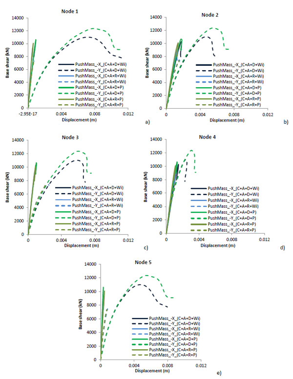
Due to a significant extension of the building, the nonlinear behavior is analysed at the varying of the selected control point. The same control points (see Fig. 23) are used in all the models, so it is possible to capture the variation in the seismic response by changing the floors stiffness, the influence of annex and of retrofitting.
5.3.1. The Church and The Annex
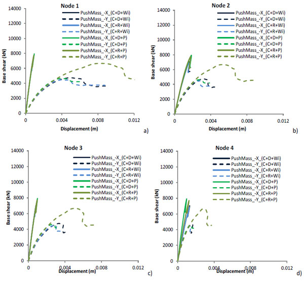
Considering the hypothesis that the annex was built at the same time of the church, behavior of the whole complex was take into account Fig. (23). For brevity issue, only the capacity curves of negative X-direction and Y-direction are reported in Fig. (24), also because the structural beahavior in the positive directions is not so different at the varying of the transversal load.
Generally, the critical load distribution for the complex is in the longitudinal direction parallel to the main nave development. The behavior on the X-direction for all the models is brittle, whereas on Y-direction there is a more ductile behavior (see Fig. 24). As already shown in the real damage survey (see Section 3), also in the NMs the major cracks involved the connection between the façade and the side walls nave, and the central vault. For this reason, the global displacements of these points were investigated (Fig. 23).
Comparing, ante-intervention NMs with post intervention NMs i.e. (C+A+D+Wi) with (C+A+D+P) and (C+A+R+Wi) with (C+A+R+P), an increment in terms of displacements and forces in both directions is evident. Likewise, in these models, it is also possible to see that the presence of rigid floors reduced the displacements but increased the lateral stiffness. In Figs. (25 and 26) the development of the cracking in the four NMs, due to horizontal loads in the -X-Direction and -Y- Direction, are shown.
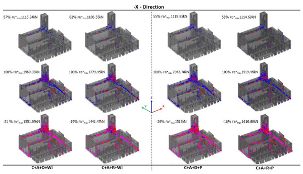
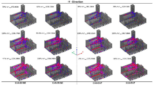
In both directions, the first crack appears on the barrel vault of the nave, and these macro-elements represent the brittle elements of the structure.
Furthermore, in X-Direction some cracking appears on the triumphal arch under the bell-tower; when the transversal load is increased, then the damages extend up to the bell tower until reaching the upper zone where the arches of the belfry are located. In Y-Direction, the cracking distribution is more uniform and limited with respect to X-Direction, but, when the load is increased, the tower becomes more damaged especially on the connection with the church walls and less damage is associated to the top of the belfry. Finally, comparing the real damages reported in Fig. (9) with those of NMs in Figs. (25 and 26) when the load act in Y-Direction, a diffuse micro-cracking is observable in the middle height of the nave walls, where lunettes with some stuccos are located. Furthermore, the cracking on the presbytery vault near the connection with the triumphal arch is always visible (see Fig. 9d) in all NMs. This confirms the reliability of the proposed NMs.
5.3.2. The Church
In order to detect the vulnerability of the isolated church, the NMs were simplified deleting the annex and obtaining (C+D+Wi), (C+R+Wi), (C+D+P) and (C+R+P) (see Figs. 12c-d-g-h). The main capacity curves are reported in Fig. (27).
The first evidence, with respect to the models with the annex, is a reduction of both resistance and stiffness. The X-Direction, as in the case with the annex, has a brittle behavior. Meanwhile, in the Y-Direction a more ductile behavior is observed.
The improvement of the retrofitting works on the roof of the church has been evaluated also in this case. More precisely in X-Direction the behavior remains almost the same, differently in Y-Direction the resistance and ultimate displacement increase.
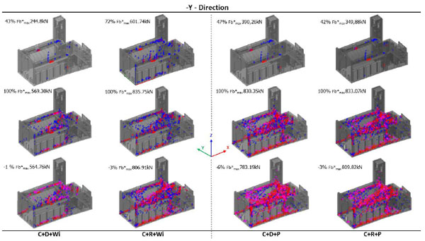
Analysing the damages for increasing values of the transversal load, as reported in Figs. (28 and 29), presence or absence of a rigid diaphragm has a minimal effect on X-direction, but it results more marked on the Y-Direction as well as in presence of the annex. In fact, the cracking evolution is concentrated around the tower near the connection between the triumphal arch and the nave walls, but when the load acts along the Y-Direction Fig. (29), NMs (C+D+Wi), (C+R+Wi), (C+D+P) and (C+R+P) more extended damages appear in the main vault and on its connection with the nave walls.

Also in this case, comparing the real damages reported in Fig. (9) with those of NMs in Fig. (29) when the load act in Y-Direction, a diffuse micro-cracking is visible in the middle height of the nave walls, where some stuccos are present. Actually, this represents a specific vulnerability of this church. Differently, in both directions, a micro-cracking is visible in the presbytery vault near the connection with the triumphal arch, as reported in Fig. (9d) where the last real damage is reported.
6. RESULTS AND DISCUSSION
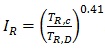
To summarize the seismic performances of the complex, according to the NMs used in this work, the Seismic Risk Index IR is used:
 |
(1) |
It might be worthy to remind that IR≥1 corresponds to a safe structure, and IR<1 corresponds to an unsafe building on the standard of the new constructions [44]. The TR,C in Eq. (1) is the return time of the seismic action that produces, for the requested SLSD, the non-respect of the inequalities d*max≤d*u (d*max is the demand, and d*u is the capacity in the equivalent s.d.o.f. system [45] or 3<q*<6), while TR,D is reported in Sect. 5.2. The use of the IR gives the possibility to work, indifferently, with PGA (International country) or TR (Italy). In fact, the exponent 0.41 in (1) is tuned to have the same scale of seismic vulnerability with IR calculated in terms of PGA [46]. Fig. (30) shows how IR differs at the varying of the control points. For all calculated IR, the intrinsic ductility q* is <3.
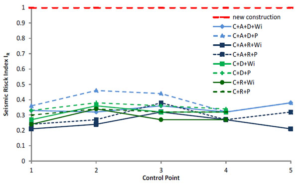
From Fig. (30) the continuous line represents the ante-intervention condition while the dashed line the post-intervention one. The main difference consists in the fact that with the retrofitting of the roof, all the indexes are bigger than the previous condition. Furthermore, another consideration is related to the presence of rigid floors, which is not always associated with major IR, as in this case. In fact, not spread rigid floors (see Fig. 12) do not permit the collaboration between the walls, and the damages accumulate in areas where this process is obviously minimum.
In order to consider the variability of the vulnerability with the annex, it is possible to say that for the model (C+A+D+Wi) IR varies from a minimum of 0.32 to a maximum of 0.38, with an average value of 0.342 and a standard deviation of 0.027; for the Model (C+A+D+P) the index varies from a minimum of 0.32 to a maximum of 0.46, with an average value of 0.39 and a standard deviation of 0.058. This means that an increment of +13% in terms of seismic risk index is obtained with the retrofitting of the roof. This is due to the presence of a better “box-like behavior” than the diaphragm stiffness effect of the church roof, which gives a global better behaviour with respect to the perfect deformable floors.
Similarly, for the model (C+A+R+Wi) the IR varies from a minimum of 0.21 and a maximum of 0.32, with an average value of 0.25 and standard deviation of 0.046; for the Model (C+A+R+P) the index varies from a minimum of 0.24 and a maximum of 0.38, with an average value of 0.296 and standard deviation 0.055. This allows to draw some considerations in presence of rigid floors and roof retrofitting noticing, in first place, that the IR has an increment of about +16%, that is bigger than the previous case with deformable floors. Even if the percentage of improvement is greater in the presence of rigid floors, the situation of increased seismic security is given in the presence of deformable floors, where an increment of +24% comparing IR of (C+A+D+P) and (C+A+R+P) is available. For this reason, it is important to stress out the fact that the behaviour is always nonlinear but, due to the low ductility of the material, the entire complex has a brittle-like behaviour in presence of rigid floors. Furthermore, in this case, the nonlinear analyses end as a very concentrated damage is reached in some parts of the complex, in particular on the main vault, and on the tower as in the case of (C+A+R+P) Figs. (28, 29).
Otherwise, considering the complete detachment of the annex, the different situation should be considered. In (C+D+Wi) the index varies from a minimum of 0.27 and a maximum of 0.36, with an average value of 0.32 and a standard deviation of 0.037; for Model (C+D+P) the index varies from a minimum of 0.33 and a maximum of 0.38, with an average value of 0.35 and standard deviation of 0.022. This means that in absence of rigid floors the retrofitting intervention gives to the structure an increment in terms of seismic resistance of about +10%. For the Model (C+R+Wi) the IR varies from a minimum of 0.24 and a maximum of 0.34, with an average value of 0.28 and standard deviation of 0.042; for the model (C+R+P) the index varies from a minimum of 0.30 and a maximum of 0.34, with an average value of 0.32 and standard deviation 0.016. Again, the complex with rigid floors and retrofitting intervention has an increment of about +13% in terms of seismic resistance, major than the condition with deformable floors. As in the previous case with the annex, comparing the deformable and rigid cases, the IR is less in the second case due to the presence of a concentrate cracking near the triumphal arch which gives unexpected numerical problems.
The variability of the obtained IR at the varying of the control points suggests the importance of considering the appropriate control point. This highlights an inherent drawback of the pushover analysis for those structures where constant rigid floors are not present in all elevations.
As can be seen, the presence of the annex increases the IR in the case of deformable floors, both with and without interventions. Differently, the presence of rigid floors and annex concentrates the damage in a little area, giving a worse seismic behavior.
CONCLUSION
The case study of “Santa Maria della Carità” church in Ascoli Piceno, hit by the L’Aquila earthquake in 2009, was useful to highlight the influence of the annexes in the structural global behaviour of churches. The observation of the damage scenario of the past (L’Aquila) and of the more actual (Marche-Abruzzo-Umbria-Lazio, 2016) earthquakes suggested this research which, with the support of a consciously restricted NMs, allows the presentation of some results about a very complex item.
The 3D nonlinear solid NMs have been used to evaluate the seismic capacity of the complex using a series of pushover analyses performed by varying the interactions among the church and the annex, by changing the stiffness of the floors and applying the effect of a past retrofitting intervention that were designed after L’Aquila earthquake. Eight different structural configurations have been considered, and their seismic risk indexes have been evaluated. These analyses provided important information on the influence of the aggregate on the seismic safety of the complex.
The influence – in terms of seismic risk index – of the choice of the control point has been analysed too, and it has been found that due to the extension of the complex, it affects the seismic response. The seismic analyses have been helpful to obtain a screening of the most vulnerable elements of the structural complex, which are the eccentric tower and the main vault. This information can be used to design local and global retrofitting works.
This paper also highlights that a good knowledge of the structure is essential to understand the seismic behaviour. Indeed, the lack of knowledge of certain parameters, such as adjacent buildings and the type of floors stiffness, can distort the response of the structure and therefore, requires more sophisticated procedures that go against the principle of minimum intervention.
CONSENT FOR PUBLICATION
Not applicable.
CONFLICT OF INTEREST
The authors declare no conflict of interest, financial or otherwise.
ACKNOWLEDGEMENTS
The authors wish to thank the Eng. M. Curzi and the Arch. R. Terpolilli of the Municipally of Ascoli Piceno, the designer Eng. M. D’Emidio and the vicar Don Angelo Cianciotti for their active cooperation. The useful help provided by Eng. Sara Vallucci, Ph.D., during the preliminary stages of the work is gratefully acknowledged.

