All published articles of this journal are available on ScienceDirect.

Seismic Performance Evaluation of a Multi-Span Existing Masonry Arch Bridge
Abstract
Introduction:
Existing old masonry arch bridges represent an architectural and cultural heritage of inestimable value because most of them were built in the last century and are still in service. They represent a very important part of roads and railways networks, having also an important strategic role. They are actually serving roads characterized by transit loads definitively heavier and more frequent than the ones of the past. Moreover, very often maintenance absence and material worn away, increased by the way by the environmental conditions, accelerate more and more the elements deterioration with a consequent loss of integrity and reduction of their carrying capacity.
Methods:
In this paper the seismic assessment of an old multi span masonry arch bridge still in service is evaluated. The bridge, located in Southern Italy, was built before the Second World War and crosses the “Cavone” River, from which it takes the name.
Results and Conclusion:
A series of numerical analyses are performed in order to evaluate its seismic performance and the model sensitivity with respect to the assumed masonry mechanical properties.
1. INTRODUCTION
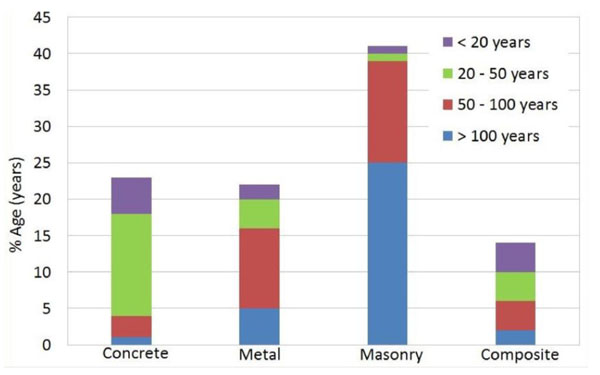
The masonry arch bridges are structures very common in Europe. As emerged from many recent studies, most of them are still in service having more than a century of life. For example, of 220.000 European railway bridges counted about 35% are more than 100 years old with a further 31% aged between 50 and 100 years. In total, it is estimated that about 60% of bridges are in masonry, 23% in concrete, and 22% metallic. Similar percentages may be also applied for highway bridges [1] (Fig. 1).
As regards the masonry arch bridges, they are very vulnerable even in moderate seismic prone areas, because no lateral action was considered during their designing. Moreover, the deterioration of the masonry accelerated by bad maintenance conditions are undoubtedly factors that increase the seismic vulnerability.
As known, their lateral seismic response is influenced by different factors such as, for example: texture, integrity, and quality of the masonry, deterioration of the mortar joints, structural geometry, and connections among the bridge elements. The knowledge of these factors is also essential to realistically simulate with an appropriate and clear analytical model the structural response of the bridge (either at global or at local level). In such a way, the obtained numerical predictions would allow bridge owners to plan maintenance strategies, and the relative interventions avoiding significant economical and social losses also in the case of moderate seismic events.
Different modeling approaches may be implemented for simulating the seismic response of the masonry arch bridges. One of the most traditional one is to model the single parts of the bridge (arches, abutments and piers) and to analyze their response under vertical and lateral loads. The analysis may be conducted either for determining the in service internal stresses supposing a linear behavior, or by imposing a failure mode and calculating the lateral loads multiplier at the element collapse (kinematic analysis). However, as demonstrated by many authors the interaction among the elements may significantly influence the bridge global response. As shown, for example, in Rota et al. (2005) [2] a typical failure mechanism for masonry arch bridges under seismic action consists of the overturning of the spandrel walls pushed out of plane by the transverse thrusts of the deck backfill. This confirms that, unlike of single parts models, a global model is required and that, in general, the interactions among the bridge elements cannot be neglected.
More refined numerical analyses may be performed with global linear or nonlinear three-dimensional models, where the masonry is modeled as continuum material. Elastic models may be preferred for studying the distribution of internal forces and their concentration without excessive computational costs. These models in general overestimate the carrying capacity, since the contribution of tensile strength of masonry is taken into account, too. On the contrary, nonlinear models allow us of describing more realistically the masonry progressive failure and the redistribution of internal forces. They have also the advantage to take into account the local interaction among the bridge elements (such as for example arch elements and backfill) but, however, they require higher computational costs for reaching the solution. It must be pointed out that some local failure mechanisms may be inhibited with specific interventions (such as for example, transverse chains for preventing the spandrel walls out-of-plane overturning). Therefore, the complexity of the global model may significantly reduce with consequent benefits from a computational standpoint.
To date many international seismic codes do not report any specific indication for seismic assessment of existing masonry arch bridges. For example, Italian code [NTC-2008, 3] and Eurocode 8 [EC8, 4] refer only to existing masonry buildings, while as for bridges no attention is paid to modeling criteria and analysis methods for seismic assessment. In general, the displacement-based design method indicated in ATC-40 (1996) [5] and FEMA 273 (1997) [6] is widely used for evaluating the transverse seismic capacity of these structures, where the static nonlinear pushover analysis is combined with the response spectrum approach. Applications of this method may be found, for example, in Pelà et al. 2009 [7].
This paper shows the transverse seismic assessment of “Cavone Bridge”, a masonry Italian multi-span arch bridge. A series of nonlinear pushover analyses are performed in order to investigate the response of the bridge by referring either to the current state or after the application of some light interventions (design state). The latter have been designed for increasing the durability of the masonry elements and, therefore, they may be reviewed as maintenance plan actions assuring a good performance during the bridge lifetime. The seismic performances are evaluated in according to the displacement-based design method [5, 6]. They reveal that in the case analyzed the bridge transverse capacity is strictly depending on the flexural response of the slender piers sunk into the riverbed. Moreover, it is shown that the influence on the bridge seismic capacity of the designed interventions is very modest. The fatigue assessment of the bridge arches may be found in Laterza et al. (2017) [8].
2. MATERIAL AND METHODS
2.1. Geometrical Data and Material Details
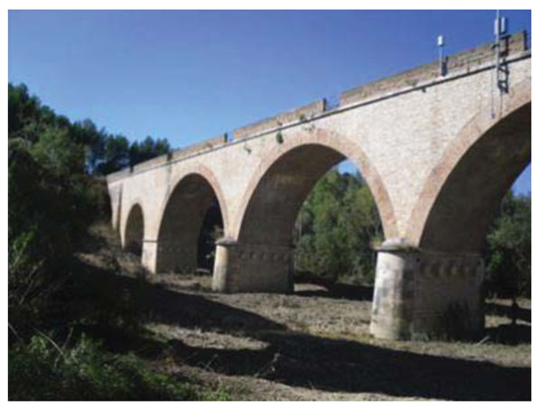
The “Cavone Bridge” considered as case study in this work, is a multi-span masonry bridge built before the Second World War (approximately during the 1930s) and located in Craco, a village in Matera Province (Italy). The bridge, actually still in service, consists of seven brick masonry arches (Fig. 2) covering an overall length of 140 m, with 5.6 m width. It has three main arches of 22 m span length and four secondary arches of 10 m span length. The three main arches are supported by two piers sunk into the riverbed (Fig. 3), having a total height from the foundation plane of about 24 m, of which 14 m above the riverbed.
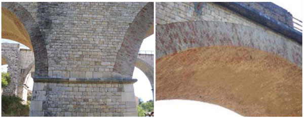
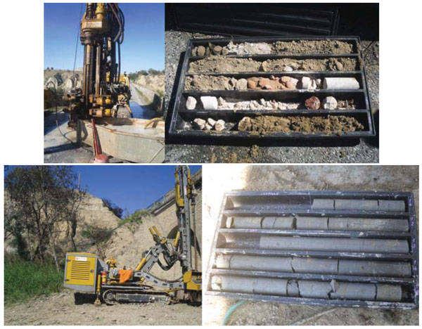
With the aim to identify the materials typology and the elements thickness some in situ tests have been performed. In particular, several core samplings have been carried out in different points from the bridge deck, reaching about 30 meters in depth in correspondence of the piers (Fig. 4). Electrical resistivity tomography (Fig. 5) tests for investigating the deck backfill (with eventual cavities) and the soil stratigraphy of the bridge have been also performed. The in-situ tests results have highlighted that the piers consist of an external layer in regular stone blocks containing a core of cohesive backfill. Whereas, the traffic load spreads in depth down to the arches through an incoherent backfill, confined by spandrel walls in regular stone blocks (Fig. 4). The site soil resulted by the means of Vs30 down-hole measurements as Type C site (deposit of stiff clay) in according to NTC-08 and EC8 classification. No test in situ or in laboratory was performed in order to evaluate the mechanical properties of the elements masonry. Therefore, in this study the literature values indicated into the NTC-08 Instructions [Circ. 2nd February 2009, n. 617, 9] for the existing masonry have been adopted, as it will be discussed hereinafter.
2.2. Numerical Model
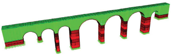
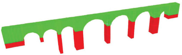
Nonlinear analyses have been performed with a finite elements model (Fig. 6) implemented in CSI BRIDGE v. 15.0 [10]. Nonlinear layered shells elements have been used for modeling the external leaf of piers/abutments stone masonry and the brick masonry arches (Fig. 7). On the contrary, linear bricks elements have been used for modeling the backfill of arches and piers/abutments (Fig. 8), by assuming a secant stiffness equal to 1/10 of the initial one of primary elements, for simulating its high deformability with respect to the transverse actions. It should be pointed out, also, that by using secant stiffness moduli, the lower the stiffness of backfill the higher the percentage of vertical load supported by the arches and external leaves of piers/abutments. In total, 1978 joints, 1291 nonlinear shells and 354 linear bricks composed the obtained numerical model. Details of the numerical model adopted can be also found in Laterza et al. [11].


No in-situ and in laboratory test was performed for determining the materials mechanical properties. Based on the limited informations collected (geometrical details and materials typology), it was reached in this work a limited knowledge level (KL1) having, in according to Instructions of NTC-08 [9], the confidence factor CF = 1,35. Moreover, in this work the masonry properties are estimated as indicated in [9].
More in detail, as far as the current state (without interventions) of the bridge is concerned, in Tables 1 and in 2 are summarized the estimated materials elastic properties and the related strengths of piers/abutments and of arches. In accordance with the Instructions of NTC-08 [8] and with the obtained KL1, the materials strengths correspond to the minimum values of the proposed ranges for the two masonry typologies considered (stone masonry and brick masonry). Whereas, the elastic moduli are equal to the average values of the proposed ones. In Tables 3 and 4 are instead reported the material properties assumed if one considers the interventions applied.
| Element | Material | Properties |
|---|---|---|
| Arches | Brick masonry | γ = 18 (kN/m3) |
| E = 1500 (MPa) | ||
| ν = 0,2 | ||
| Backfill | γ = 18 (kN/m3) | |
| E = 150 (MPa) | ||
| ν = 0,2 | ||
| Piers/Abutments masonry | Stone blocks masonry | γ = 22 (kN/m3) |
| E = 2800 (MPa) | ||
| ν = 0,2 | ||
| Backfill | γ = 18 (kN/m3) | |
| E = 280 (MPa) | ||
| ν = 0,2 |
| Uniaxial strength |
Shear strength
(Ducker-Prager Parameters) |
|||
|---|---|---|---|---|
| Element/Material |
Compressive strength
fc (MPa) |
Tensile strength
ft (MPa) |
Friction angle
Φ (°) |
Coesion
c (MPa) |
| Arches Brick masonry |
2,40 | 0,09 | 68° | 0,22 |
| Piers/abutments Stone blocks Piers/ Abutments |
6,00 | 0,135 | 73° | 0,45 |
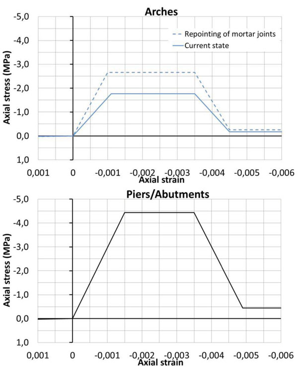
Fig. (9) shows the uniaxial stress-strain relationships in compression assigned to the arches and piers/abutments material. It has been assumed an elasto-plastic law up to the ultimate strain of 0,35%, value suggested as ultimate strain in CNR-DT 200 R1 [2013, 12]. As for the post-peak behavior, for avoiding solution convergence problems, it is being defined a descending linear branch having the same inclination of the ascending one, with a residual compressive strength assumed in this case equal to 1/10 of the strength peak. For sake of comparison, in the Fig. (9) is also plotted the stress-strain relationship when a deep repointing of arches mortar joints is considered. This intervention designed for improving the masonry durability leads as well, as indicated in [9], to increase of 1,5 times the compressive strength of the restored masonry.
| Element | Material | Properties |
|---|---|---|
| Arches | Brick masonry | γ = 18 (kN/m3) |
| E = 2250 (MPa) | ||
| ν = 0,2 | ||
| Backfill | γ = 18 (kN/m3) | |
| E = 225 (MPa) | ||
| ν = 0,2 | ||
| Piers/Abutments masonry | Stone blocks masonry | γ = 22 (kN/m3) |
| E = 2800 (MPa) | ||
| ν = 0,2 | ||
| Backfill | γ = 18 (kN/m3) | |
| E = 280 (MPa) | ||
| ν = 0,2 |
| Uniaxial strength |
Shear strength
(Ducker-Prager Parameters) |
|||
|---|---|---|---|---|
| Elements/Materials |
Compressive strength
fc (MPa) |
Tensile strength
ft (MPa) |
Friction angle
Φ (°) |
Coesion
c (MPa) |
| Arches Brick masonry |
3,60 | 0,135 | 68° | 0,34 |
| Piers/abutments Stone blocks Piers/ Abutments |
6,00 | 0,135 | 73° | 0,45 |
In the numerical simulations layered shells elements have been implemented for reproducing also the nonlinear shear behavior of masonry, making use of Drucker–Prager failure criterion (Chen and Han, 2007) [13]. The friction angle ϕ and the coesion c have been derived starting from the uniaxial strengths in tension ft and in compression fc, as follows:
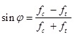 |
(1) |
 |
(2) |
The obtained Drucker–Prager parameters in this case study are reported in Tables 2 and 4, by referring to the current state and design state, precisely.
2.3. Numerical Simulations
The transverse seismic assessment of the Cavone bridge has been carried out by using the Capacity Spectrum method indicated in NTC-08 [3], ATC-40 [5], FEMA 273 [6], combining the nonlinear static analysis (pushover) with the response spectrum approach. In according to the performance based design philosophy, the adopted method assesses the displacement capacity of an equivalent single DOF system and compares it with the seismic demand.
A preliminary linear modal analysis has been performed for determining the natural frequencies and the modal shapes of the bridge. The analysis has shown the importance of the first vibration mode on the global response, characterized by a transverse response orthogonal to the plane containing the pier axes. This confirms that the transverse direction is the most vulnerable one for the bridge, and for this reason the capacity in this direction is investigated.
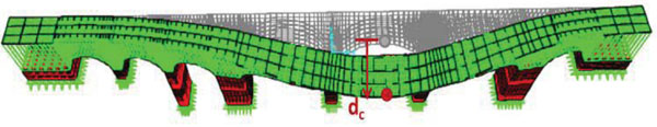
The bridge capacity curve has been obtained by applying a monotonic incremental lateral forces system proportional to the displacements pattern of the first vibration mode up to the collapse. This loading system simulates the inertia forces that would act on the elements during a transverse seismic excitation. The displacements pattern obtained with the preliminary modal analysis is shown in Fig. (10), where also is highlighted the control node corresponding to the keystone of the central main arch. Moreover, the loading of the numerical model has been applied in two different steps. At first, all the vertical loads have been applied. Afterwards, the lateral forces system is incrementally increased up the bridge collapse.
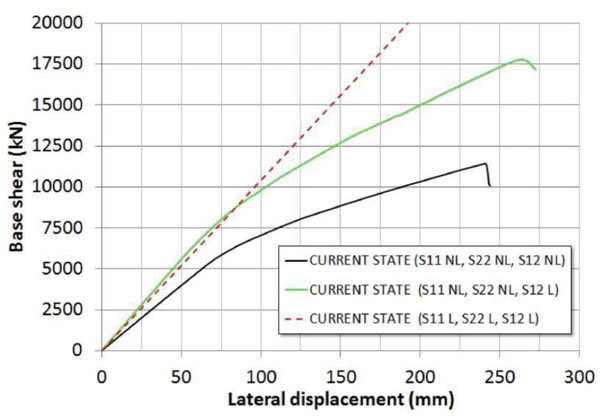
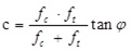
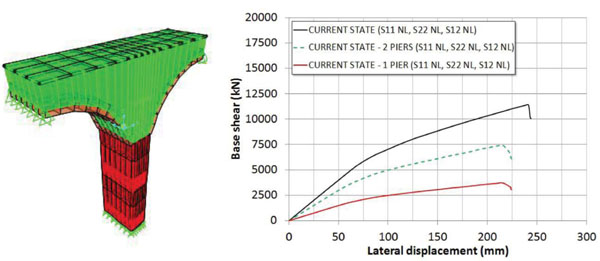
Hereinafter are reported the results of a series of nonlinear pushover analyses carried out with the implemented model of the bridge. In particular, Fig. (11) shows the influence on the pushover curve of the nonlinear shear behavior of masonry in the current state. At this scope three responses are compared, obtained by considering the following constitutive laws: indefinitively elastic in the uniaxial and shear direction (S11 L, S22 L and S12 L curve); nonlinear behavior only in the uniaxial direction (S11 NL, S22 NL, and S12 L curve); nonlinear behavior in the uniaxial and shear direction (S11 NL, S22 NL, and S12 NL curve). In the Fig. (11) S11 and S22 indicate the axial stresses along the vertical and horizontal directions, respectively, while S12 refers to the shear stresses. By comparing the obtained curves, it is easy to note that in the case analyzed the nonlinearities due to the shear behavior are significant into the global transverse response of the bridge. Moreover, the control node displacement reaches a maximum value dmax at failure of about 23 cm, corresponding to a drift of 0.95% calculated with respect to the riverbed central piers. Also, in Fig. (12) the contribution of the arches and piers to the global response is investigated. The pushover curves are obtained by alternatively considering the arches (Arches NL–Piers/Abutments L) or the piers (Arches L - Piers/Abutments NL) with a nonlinear behavior in both uniaxial and shear direction. The comparison clearly illustrates that the transverse nonlinear response of the bridge is almost entirely due to the nonlinear response of the piers/abutments, while the arches nonlinear contribution is considerably negligible. More in detail, the nonlinear capacity curve of the bridge mainly depends by the two piers sunk into the riverbed, as it is possible to conclude with the comparisons plotted into the Fig. (13). This Figure shows the pushover curve of a single riverbed pier, and the doubled one referred to the two piers considered acting in parallel against lateral forces. As it is clear to note, the so derived pushover curve is close to the global one. In particular, the initial stiffness results approximatively equal to 70% of the global initial one, while the peak strength is about 60% of the global strength peak of the bridge. Evidently, the other piers and the abutments of the bridge offer the remaining resistance on the global response. Starting from the results obtained, it is possible to conclude that the transverse response of the bridge is characterized only by the flexural response of the vertical elements, and mainly by the riverbed piers.
In order to investigate the implemented model sensitivity with respect to the assigned mechanical parameters a series of pushover analyses have been carried out, too. In particular, the sensitivity analyses have been focused on the values of the compressive and tensile strength, and of the friction angle to be assigned to the nonlinear masonry elements. The groups of the assigned parameters to piers/abutments and arches are reported in Table (5), where also are highlighted for each group the assigned values in the current state when the seismic assessment of bridge is performed.
| Id analysis | Compresssive strength (MPa) | Tensile strength (MPa) | Friction angle (°) | ||||
|---|---|---|---|---|---|---|---|
|
Piers/
Abutments |
Arches |
Piers/
Abutments |
Arches |
Piers/
Abutments |
Arches | ||
| Pushover - Current condition | 4,44 | 1,77 | 0,1 | 0,066 | 73 | 68 | |
| 1 | Pushover 1.1 | 3 | 1,77 | 0,1 | 0,066 | 73 | 68 |
| Pushover 1.2 (Current condition) | 4,44 | 1,77 | 0,1 | 0,066 | 73 | 68 | |
| PushOver 1.3 | 6 | 1,77 | 0,1 | 0,066 | 73 | 68 | |
| 2 | Pushover 2.1 (Current condition) | 4,44 | 1,77 | 0,1 | 0,066 | 73 | 68 |
| PushOver 2.2 | 4,44 | 3 | 0,1 | 0,066 | 73 | 68 | |
| PushOver 2.3 | 4,44 | 4 | 0,1 | 0,066 | 73 | 68 | |
| 3 | Pushover 3.1 (Current condition) | 4,44 | 1,77 | 0,1 | 0,066 | 73 | 68 |
| PushOver 3.2 | 4,44 | 1,77 | 0,2 | 0,066 | 73 | 68 | |
| PushOver 3.3 | 4,44 | 1,77 | 0,3 | 0,066 | 73 | 68 | |
| 4 | Pushover 4.1 (Current condition) | 4,44 | 1,77 | 0,1 | 0,066 | 73 | 68 |
| PushOver 4.2 | 4,44 | 1,77 | 0,1 | 0,2 | 73 | 68 | |
| PushOver 4.3 | 4,44 | 1,77 | 0,1 | 0,3 | 73 | 68 | |
| 5 | PushOver 5.1 | 4,44 | 1,77 | 0,1 | 0,066 | 60 | 68 |
| Pushover 5.2 (Current condition) | 4,44 | 1,77 | 0,1 | 0,066 | 73 | 68 | |
| PushOver 5.3 | 4,44 | 1,77 | 0,1 | 0,066 | 80 | 68 | |
| 6 | PushOver 6.1 | 4,44 | 1,77 | 0,1 | 0,066 | 73 | 50 |
| PushOver 6.2 | 4,44 | 1,77 | 0,1 | 0,066 | 73 | 60 | |
| Pushover 6.3 (Current condition) | 4,44 | 1,77 | 0,1 | 0,066 | 73 | 68 | |
| PushOver 6.4 | 4,44 | 1,77 | 0,1 | 0,066 | 73 | 80 | |
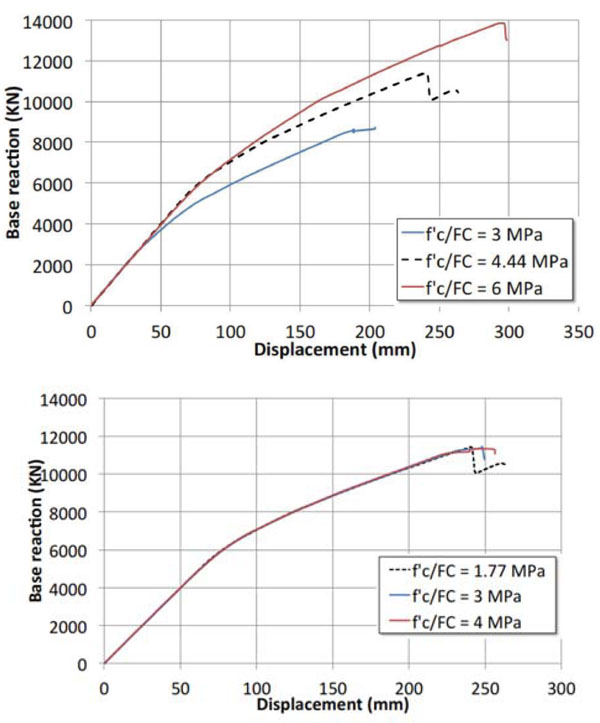
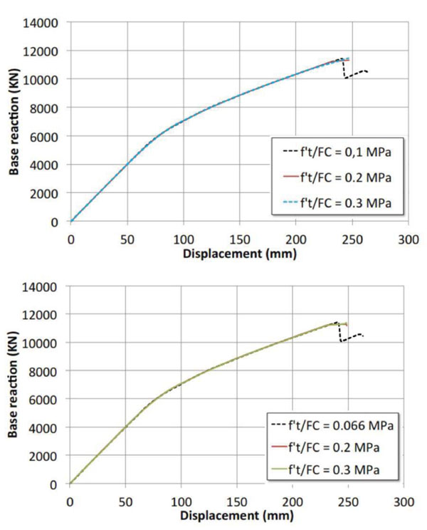
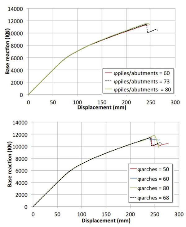
The results of the parametric pushover curves are illustrated from Figs. (14-16), where the reference curve obtained in the current state is reported with a dashed line. It is easy to note that in the case analyzed only the compressive strength of piers/abutments influences the global transverse response Fig. (14a), while the response is unchanged by varying the compressive strength of the arches Fig. (14b). By doubling the compressing strength of piers/abutments the lateral strength of the bridge is almost doubled. Again, these results confirm that the nonlinear response of the bridge is mainly depending on the nonlinear response of the piers/abutments. Unlike the compressive strength, the performed analyses put on light that the tensile strength (Fig. 15) is not an essential parameter for realistically evaluating the seismic response of the studied bridge. Finally, the variability of the friction angle within the range considered is also irrelevant for the global response, as revealed by the comparisons depicted in Fig. (16).
2.4. Seismic Performance Evaluation of the Bridge
The seismic evaluation of the Cavone bridge has been performed in accordance with the ATC-40 Capacity Spectrum Method [5]. The global transverse response of the bridge has been converted into the response of an equivalent nonlinear single degree of freedom (SDOF) system, and directly compared with the seismic demand calculated with the response spectrum.
Fig. (17) shows in the ADRS plane (spectrum acceleration spectrum displacement plane), the bridge capacity spectrum and the reduced seismic demand from the elastic response spectrum (5% damped) in according to NTC-08 code [3]. The performance point is evaluated in the current state for two different ultimate limit states of the structure: Life Safety Limit State (LS) and Collapse Prevention Limit State (CP), by considering for both a ground motion return period of 75 years. The obtained results are shown in Table 6, where the adopted symbols assume the following meanings:
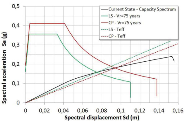
| State Limit | V (kN) | D (m) | Sa (g) | Sd (m) | Teff (sec) | βeff (%) |
|---|---|---|---|---|---|---|
| LS | 7866 | 0.120 | 0.160 | 0.076 | 1.384 | 9.90 |
| CP | 8916 | 0.152 | 0.184 | 0.096 | 1.452 | 11.80 |
- V: base reaction shear of the capacity curve corresponding to the performance point;
- D: displacement of the control point in the pushover curve (capacity curve) corresponding to the performance point;
- Sa: spectral acceleration of the equivalent elementary oscillator corresponding to the performance point in the ADSR plane (capacity spectrum);
- Sd: spectral displacement of the equivalent elementary oscillator corresponding to the performance point the ADSR plane (capacity spectrum);
- Teff: effective period of the equivalent elementary oscillator corresponding to the performance point;
- βeff: equivalent damping ratio of the equivalent elementary oscillator corresponding to the performance point.
The performed seismic assessment shows, in according to the methodology adopted, that the bridge reaches the displacement demand at both the considered limit states (life safety and collapse prevention) and, therefore, and it always results seismically adequate. It should be pointed out that, due to the low vulnerability, the simulated global response has been obtained by neglecting any local collapse mechanism. In general, in a global numerical modal this assumption can be made either the seismic vulnerability of local mechanisms is low or else is greatly abated by the means of some local interventions (such transverse steel chains against the out-of-plane overturning of spandrel walls).
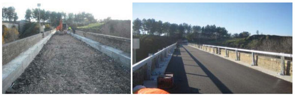
In this study are also taken into account the influence on the seismic response of some light interventions mainly addressed to increase the durability of the masonry elements. In order to improve the spreading of traffic loads on the deck a remaking of the road pavement with a lightweight reinforced concrete slab was applied (Fig. 18). The slab had a thickness of about 50 cm and was simply placed on the backfill without any mechanical linking with the underlying arches and piers. It was also considered a restoring of the elements masonry texture with equal blocks and a deep repointing of all arches joints by using a salt-resistant, natural hydraulic lime and eco-pozzolan mortar. Furthermore, two layers of uniaxial C-FRP wraps were applied on the intrados of three main arches as local strengthening for improving the element resistance against the vertical cyclic loadings (Fig. 19).
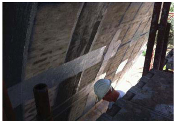
The numerical simulations have been performed also in the design state (i.e. by considering the described interventions) by assigning to the elements the updated material properties indicated in the Tables 3 and 4. As far as the modeling of the C-FRP wraps is concerned, they have been considered as reinforcements of fibers sections of nonlinear shells, having a Young’s modulus equal to 230 GPa, a total thickness of 0,33 mm (two layers of C-FRP of 0,133 mm), and having only tensile strength corresponding to the wraps debonding failure. This strength has been calculated in according to [12], resulting in this case equal to fdd=316 MPa.
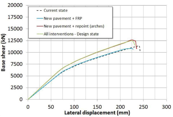
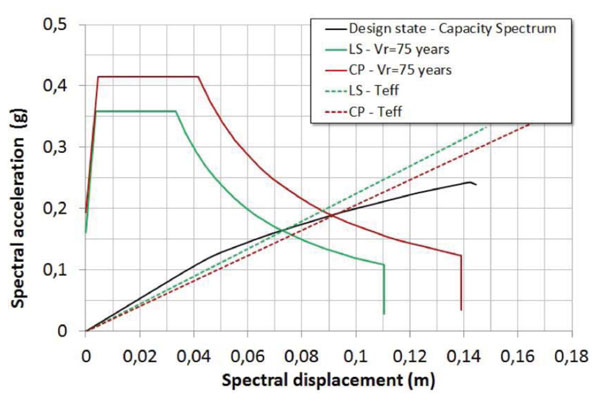
In Fig. (20) are shown the simulated global responses obtained with pushover analyses by considering the aforementioned interventions (‘all interventions – design state’ curve). For sake of clarity, in the same Figure is also reported the bridge response referred to the current state (i.e. without interventions), and the ones obtained by individually applying the designed interventions. If one compares the responses it is very clear to note that the repointing of the arches mortar joints is the only intervention, among the designed ones, that slightly modifies the global response in terms of both stiffness and strength. Conversely, the other interventions do not produce any variation with respect to the current state. Moreover, in Fig. (21) is reported the related seismic performance evaluation in according to ATC-40 method, numerically summarized in Table 7. It must be pointed out that with all the designed interventions the seismic performance is quite similar to the one obtained in the current state demonstrating their light invasiveness. The interventions do not substantially alter the pre-existing bridge response and, therefore, they are only aimed to the conservation of the masonry elements. Finally, in Fig. (6) are compared the values of the α ratio, given by the ratio of the displacement demand (Ddemand) to the displacement at the collapse (Dcapacity). It provides a measure of the distance between the demand and the collapse in terms of lateral displacement. In the case analyzed, due to also to the moderate seismic hazard of the site, Ddemand is about half of Dcapacity at the Life Safety Limit State (LS), while this ratio increase to about 2/3 at the Collapse Prevention Limit State (CP). Again, the comparison (Fig. 22) clearly shows that global response is unchanged owing to the interventions considered, since the α ratios are substantially equal in the two structural conditions (before and after the interventions).
| State Limit | V (kN) | D (m) | Sa (g) | Sd (m) | Teff (sec) | βeff (%) |
|---|---|---|---|---|---|---|
| LS | 8737 | 0.116 | 0.166 | 0.074 | 1.336 | 9.80 |
| NC | 10006 | 0.148 | 0.193 | 0.094 | 1.339 | 11.50 |

RESULT
A series of nonlinear pushover analyses are performed in order to evaluate the seismic performance and the model sensitivity of a multi-span existing masonry arch bridge.
DISCUSSION
The transverse response of the case study is simulated with nonlinear finite elements model in accordance with the target displacement method proposed in ATC-40. The obtained results highlight the importance of simulating the shear nonlinear behavior of the primary masonry elements (arches and piers/abutments). The numerical results point out that the global response mainly is depending by the central slender piers, that represent the most vulnerable elements of the bridge.
CONCLUSION
In this paper the seismic assessment of an existing multi span masonry arch bridge has been evaluated. The transverse response has been simulated with a nonlinear finite elements model in accordance with the target displacement method proposed in ATC-40. Moreover, the numerical model sensitivity with respect to the masonry mechanical properties has been investigated through a series of pushover analyses, too.
The obtained results have shown the importance of simulating the shear nonlinear behavior of the primary masonry elements that, in the case analyzed, consist in arches and in external leaves of piers/abutments. More in detail, the numerical results have pointed out that in the case analyzed the global response mainly depends by the central slender piers that represent the most vulnerable elements of the bridge. It is important to remark that the simulated global response has been evaluated unless of any local collapse mechanism of elements, such as for example the out-of-plane overturning of spandrel walls.
The pushover analyses have also shown that, coherently with the adopted seismic assessment method, the bridge satisfies even in the current state the displacement seismic demand for both the considered ultimate limit states (life-safety and collapse prevention). Furthermore, the designed local interventions may be intended as “light interventions” since they do not significantly modify the existing global response of the bridge. Therefore, they are only addressed to preserve the durability and the integrity of the elements by restoring the masonry resistance.
Finally, the sensitivity analyses represent a speed-up approach for preliminary determining the primary elements and the mechanical properties to be mainly investigated. In this case study, they have demonstrated that only the compressive strength of the slender piers influences the global response in terms of stiffness and strength. This evidence is very useful in order to focus additional material investigations only on these bridge elements. Hence, the knowledge level may be improved by minimizing the investigations number with the relative costs.
CONSENT FOR PUBLICATION
Not applicable.
CONFLICT OF INTEREST
The authors declare no conflict of interest, financial or otherwise.
ACKNOWLEDGEMENTS
The authors gratefully acknowledge the Department of Transportation of the Matera Province that financially supported this work.

