All published articles of this journal are available on ScienceDirect.
Mechanical Properties Research on Suspended-dome Structure with Discontinuous Support Under Different Parameters
Abstract
Introduction:
For suspended-dome with big partial hole, two kinds of feasible plans were proposed.
Method:
One of the plans was to adjust suspended-dome’s members, and another to build auxiliary supporting system to support the suspended-dome with columns together. These kinds of suspended-dome’s main structural parameters include stiffness, member force, steel consumption, support reaction and stability, and parametric analysis is based on these parameters.
Conclusion:
Firstly,the scope of application was illustrated for the former plan. Then, an equivalent vertical stiffness algorithm was put forward for the latter plan. In the latter plan, limit stiffness constant was introduced to quantify the method for solving discontinuous support problem.
1. INTRODUCTION
Suspended-dome was first put forward by Prof. Kawaguchi, A. Masaru, I. Tatemichi, et al [1]. As a kind of large-span space structure, suspended-dome structure combines advantages of cable dome with single-layer shell. The suspend-dome system is composed of single-layer shells, prestressing cable and strut. The upper end of the strut is hinged to the single-layer reticulated shell and lower end of it is connected together by hoop which forms a complete closed force system. Under the action of external force, the thrust of the upper single-layer shell is reduced due to the pretension of cable. The internal force is firstly transmitted from single-layer shell to strut, then from strut to cable, and finally from cable to support [1]. Currently, suspended-dome has been widely used all over the world. As a kind of self-balanced spatial structure architecture, one important reason why suspended-dome is widely welcomed by designers is that it has an explicit force transfer path and excellent mechanical properties. Another reason is that it reduces the amount of steel used in large span structure [1 - 3]. Somehow this structure’s unique characteristics determine that its shape should meet some basic requirements, such as regularity, integrity and symmetry, etc. Due to the architecture functional requirements, some public buildings such as stadium, concert hall and auditorium that use suspended-dome structure usually need big partial holes. And because of this, it is difficult to ensure that the position of the supporting column can be uniformly and continuously arranged under the roof structure. Consequently, reasonable solutions for suspended-dome structure with discontinuous supporting have great practical significance.
2. RESEARCH ON FEASIBILITY SOLUTIONS
Two kinds of schemes, with or without assistant support, were proposed for suspended-dome with discontinuous support. The schematic diagram of the two feasible schemes is shown in Fig. (1).
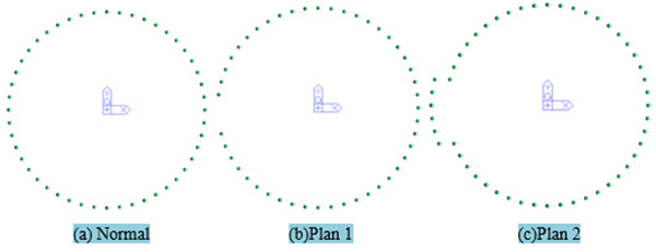
Plan 1, parametric analysis without assistant support: The substructure provides a single circle concrete column as the supporting system. The part which lacks column cannot form an assistant supporting structure, and this problem only can be solved by adjusting members’ specification of the suspended-dome.
Plan 2, parametric analysis with assistant support: In addition to the substructure, a single circle concrete column is provided as the supporting system, and the missing columns’ part of the structure can be replaced by the assistant supporting system. This system can support the suspended-dome with the external concrete column together.
Circular Kiewitt suspended-domes of 40m, 80m and 120m span were selected as examples to be applied to the two kinds of schemes and corresponding parametric analysis plans.
3. PARAMETRIC ANALYSIS OF NONE ASSISTANT SUPPORT PLAN
In this section, parametric analysis plan was established for two most important parameters: the number of missing columns and the span. The applicability of the plan was determined by the change rule of all parameters.
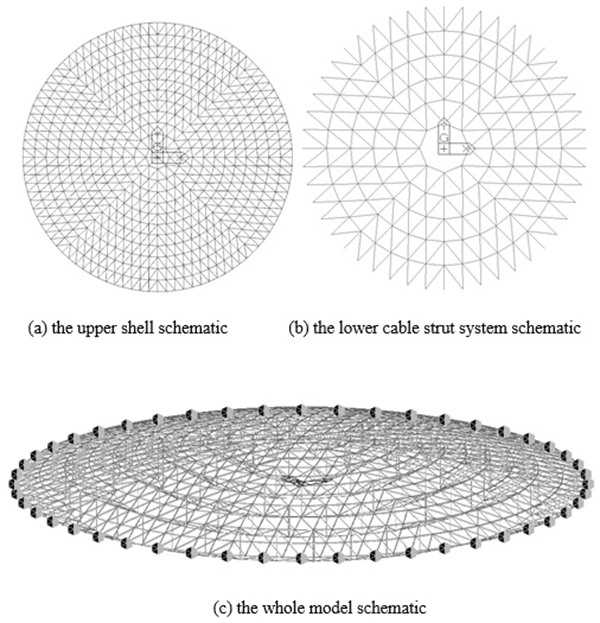
As for the two plans above, we chose standard circular Kiewitt suspended-dome structure to conduct the analysis and selected parameters of span, span ratio and number of missing columns for research. The shell part of the structure was K-8 type, and the lower cable strut system was in the form of a thin cable with 5 rings, and the support was made of the three direction hinged support. We used Midas Gen software [4, 5] to establish the model and conduct the analysis. In the model, beam element was simulated for rod element in shell, truss element for the compression strut, tension-only element for cable and pull rod. The basic analysis model is shown above Fig. (2).
3.1. Parametric Analysis Condition
In most suspended-dome structures, the interval between columns is generally between 6 and 8 m. The number of missing columns is the most direct parameter. Therefore, the number of missing columns can basically reflect the span of the structure of the missing area [6].
The parameters of the suspended-dome structure are set as shown below. Its planar projection is the standard circular. The K-8 type is selected as the net shell part form, and the 3m-long rods are selected to control the grid size. The lower cable-strut system is formed for thin rope type. The rise-span ratio is 1/12, and the height of poles is 4.5 m. The number of missing columns is between 1 and 4, the main spans are 40 m, 80 m and 120 m.
Midas Gen was used to establish the model and analyze the static as well asdynamic performance, while ABAQUS was used to analyze stability of the structure [7]. The maximum members, the maximum displacement, the maximum support reactions, the amount of steel and the stability of the structure were selected as the comparison parameters. Maximum members reflected the maximum stress, maximum displacement reflected the overall stiffness of the structure, maximum support reactions reflected the feasibility of structure, and the amount of steel reflected the rationality of the structure, respectively. The failure mode and the load factor-displacement curve can be obtained through stability analysis. Through considering the five parameters mentioned formerly, the rationality of the structure can be proved.
(I)Parametric analysis results of suspended-dome of 40m span
The significance of the parameters which are not shown in the following table has the same meaning in this table.
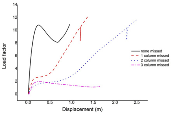
As shows in the Table 1, for the suspended-dome with 40m span, the number of missing columns only affected the selection of rod specification and specification of rod was always controlled by the slenderness ratio. With the increase of number of missing columns, the displacement showed a consistent trend, but the displacement was not the right controlling factor. The maximum support reaction’s increment was more noticeable than the displacement. When the number of missing column hatted 3, the maximum support reaction had reached 10 times as much as a normal condition. The amount of steel was less affected by the number of missing columns. From the stability, the lack of columns would cause local vibration. According to load factor-displacement curves (Fig. 3), when the number of missing column was 1 or 2, the limit load factor change fewer, and the displacement matched by the ultimate load increased little. Nonetheless, there was a decrease of slope in the climbing part. When the number of missing column was up to 3, the superme load factor reached 1.95, which caused a falling part, not meeting the design needs. Above all, for the suspended-dome of 40m span, the missing number of columns was limited to 2 [8 - 11].
| Comparison of Parameters | Numbers of Missing Column | ||||
| none | 1 | 2 | 3 | 4 | |
| Maximum member specifications | Φ180×8 | Φ180×8 | Φ180×8 | Φ245×12 | Φ245×12 |
| Displacement, mm | 6 | 20 | 32 | 76 | 74 |
| Maximum support reactions, kN | 86 | 171(1.98) | 300(3.49) | 910(10.58) | 1297(15.1) |
| Amount of steel, kg/m2 | 61.55 | 61.55 | 61.55 | 62.85 | 62.9 |
| Limit load factors | 10.81 | 10.58 | 10.39 | 1.96 | — |
(II)Parametric analysis results of suspended-dome of 80m span
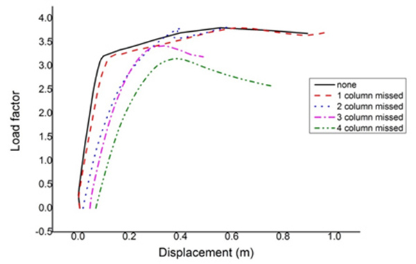
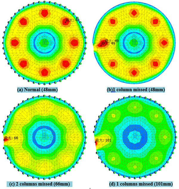
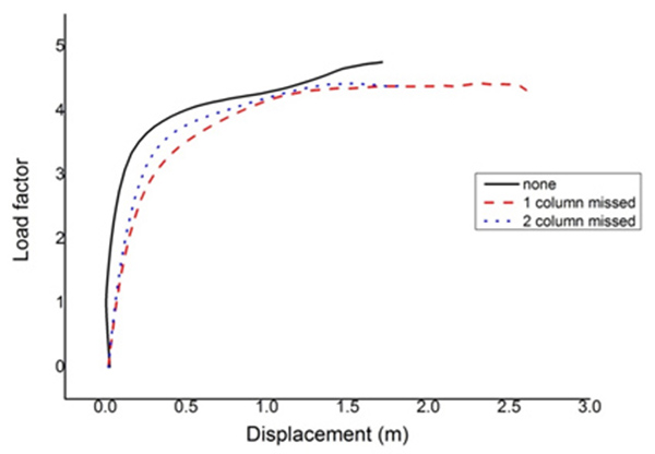
As shows in the Table 2, for the suspended-dome of 80m span, when the number of missing columns was more than 2, the members stress showed a significant change, but the amount of steel changed slightly. The displacement was extended with the increase of the number of missing columns. When the number of missing columns was up to 4, the reaction force was 9 times higher than the normal condition. The stability could consist of three stages with the increase of the number of missing columns. On the first stage, when the number of missing columns was smaller, the stability was affected slightly, with a little decrease of the overall stiffness. As is shown in Fig. (4), when the number of missing column was 1, the failure mode was similar to the normal condition.
| Comparison of Parameters | Numbers of Missing Column | ||||
|---|---|---|---|---|---|
| none | 1 | 2 | 3 | 4 | |
| Maximum member specifications | Φ180×8 | Φ219×10 | Φ219×10 | Φ402×14 | Φ500×16 |
| Displacement, mm | 48 | 49 | 66 | 101 | 110 |
| Maximum support reactions, kN | 283 | 438 (1.55) |
615 (2.17) |
1897 (6.70) |
2637 (9.31) |
| Amount of steel, kg/m2 | 64.27 | 64.27 | 64.31 | 64.8 | 65.13 |
| Limit load factors | 3.8 | 3.79 | 3.78 | 3.42 | 3.15 |
On the second stage, the missing column started to affect the overall stability. The local vibration mode occurred but the feature value was a little bit larger. Besides, the ductility decreased, which was reflected in the material-geometry double nonlinear. According to Fig. (4), when the number of missing column was 2, the failure mode was shown as the dramatic increase of the whole and the local displacement, accompanied by excessive deformation. Then, the properties of the most outer ring cable declined sharply, until the structure damaged.
On the third stage, part missing of columns leaded a profound impact on the overall stability of the structure. In the process of buckling analysis, it appeared local vibration mode which was more advanced than normal condition. In this process, limit load factors decreased and integral curve showed the same trend as the load coefficient- displacement curve of single layer reticulated shell. And these performances show that effect of the cable strut system could be reduced significantly by a lack of excessive columns. Just as shows in the load factor- displacement curve in Fig. (4), when the structure had a lack of 3 or 4 columns, the failure mode of the structure was indicated by the dramatic increase of the displacement in part of the structure. The local member failure first, then the other members which near the damaged member failure which caused the area of lacking columns failure, and then the outer ring became invalid because of large deformation, finally the whole structure damage. In summary, as for the suspended-dome of 80m span (Fig. 5), the missing number of columns was limited to 2.
(III)Parametric analysis results of suspended-dome of 120m span
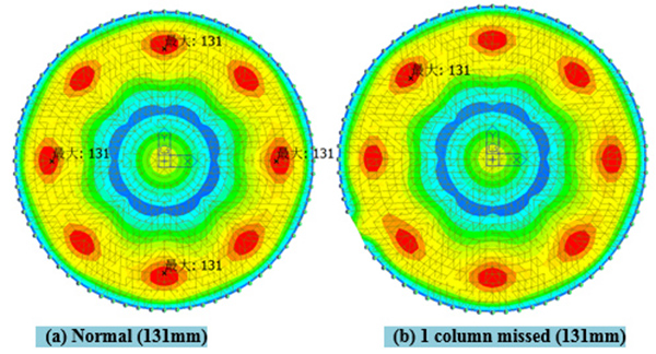
As shown in the Table 3 and Figs. (6 and 7), for the suspended-dome of 120m span, when the number of missing columns was 1, the effect on members of stress was significant, but the affected area was small. For stability, when the structure was a shortage of 2 columns, the mode was still dominated by the whole vibration and the first 50 vibration modes of the structure did not show local vibration. Therefore, we were able to get the load factor-displacement curves above. The maximum value of the support reaction increased with the growth of the number of missing columns. When the structure lacked 3 columns, its maximum member specification must be Φ630 x 16 or more, which exceeded the limit, so the number of missing columns were limited to 2 [8 - 11].
| Comparison of Parameters | Numbers of Missing Column | |||
|---|---|---|---|---|
| none | 1 | 2 | 3 | |
| Maximum member specifications | Φ245×12 | Φ245×12 | Φ500×16 | >Φ630×16 |
| Displacement, mm | 131 | 131 | 131 | — |
| Maximum support reactions, kN | 569 | 803 (1.41) | 1666 (2.93) | — |
| Amount of steel, kg/m2 | 86.57 | 86.57 | 86.98 | — |
| Limit load factors | 4.43 | 4.42 | 4.42 | — |
3.2. Parametric Analysis of Suspended-dome Under Various Span
The limit value of plan 1 and the comparison results between normal and the model under its respective limits are listed in Table 4.
| Span, m | Numbers of Missing Column | Maximum Members | Displacement, mm | Maximum Support Reactions, kN | Amount of Steel, kg/m2 | Limit Load Factors |
|---|---|---|---|---|---|---|
| 40m | 0 | Φ180×8 | 6 | 86 | 61.55 | 10.81 |
| 2 | Φ180×8 | 32 | 300 (3.49) | 61.55 (1.000) | 10.39 | |
| 53.3m | 0 | Φ180×8 | 17 | 137 | 62.34 | 8.83 |
| 2 | Φ325×12 | 89 | 1162 (8.48) | 62.84 (1.008) | 8.52 | |
| 66.6m | 0 | Φ180×8 | 48 | 283 | 92.75 | 6.78 |
| 2 | Φ325×12 | 82 | 1380 (4.88) | 93.26 (1.005) | 6.52 | |
| 80m | 0 | Φ180×8 | 48 | 283 | 64.27 | 3.8 |
| 3 | Φ402×14 | 101 | 1597 (5.64) | 64.80 (1.008) | 3.42 | |
| 93.3m | 0 | Φ180×8 | 84 | 352 | 64.98 | 3.24 |
| 3 | Φ560×16 | 84 | 2165 (6.15) | 66.73 (1.027) | 3.22 | |
| 106.6m | 0 | Φ219×10 | 100 | 518 | 87.98 | 4.24 |
| 2 | Φ450×14 | 97 | 1653 (3.19) | 88.68 (1.008) | 4.25 | |
| 120m | 0 | Φ245×12 | 131 | 569 | 86.57 | 4.43 |
| 2 | Φ500×16 | 131 | 1666 (2.93) | 86.98 (1.005) | 4.42 |
After analyzed the data in Table 4, we found that the data show the following regularities under different spans.
(1) With the increase of the span and the number of missing columns, maximum stress increases faster,which mainly centered on the ring bar. Lack of columns only affects the stress of the partial members of missing area, as for steel consumption of this structure, the effects can be ignored.
(2) With the number of missing columns rise, local displacement gradually increases. When the maximum displacement presents in the position of missing area, the displacement increases significantly when the number of missing columns grows. Support reaction has a significant change with the number of missing columns increase. It should be pointed out that the support reactions of the edge columns are one of the controlling reasons of whether the structure is feasible.
(3) The lack of column has a complex influence on the structural stability. According to the local stiffness in the area of missing column, stability of the structure has a different performance. In some analysis model, a phenomenon occurred that the stiffness of the column is more than that of the original structure and the limit load coefficient slightly increase as the local bar specifications become larger. While in general, the limit load factor decreases with the increase of span.
In a word, when the number of missing columns is not more than 2, this plan is much more reasonable.
4. PARAMETIC ANALYSIS OF ASSISTANT SUPPORT PLAN
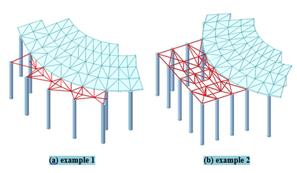
Besides the below structure provides a single circular concrete column as the supporting system, the missing columns’ part of the structure can be replaced by the assistant supporting system. And this is able to support the suspended-dome with the external concrete column together. Depending on the actual situation, the local assistant supporting system can choose different forms. We have simulated two kinds of local assistant supporting systems as shown in Fig. (8), and were emphasized in red color.
4.1. The Theory of Equivalent Vertical Stiffness Based on Classical Beam Theory
Because of a variety of specific forms of auxiliary support system, when studying the applicability of this system, the mechanical properties of its own have not been considered, and only the vertical supporting stiffness provided by the suspended-dome’s bearings will be analyzed. The assistant supporting system can be simplified as sketched in Fig. (9).

In which A, B are the position of end columns and C, D, E are the position of the missing columns. The beam between A and B work as end columns’ supporting effect. Where C, D, E, are spring bearings, representing the assistant supporting system. The vertical stiffness of node C, D, E is vertical stiffness provided by the assistant supporting system for suspended-dome, respectively.
However, because of various specific forms of local truss, the stiffness ratio of AB beam and CDE spring support cannot be determined. The stiffness of the spring bearing is also not necessarily the same. According to the most unfavorable conditions, this mean this beam is considered as hinged beam with supporting point. Assuming the beam length is l and the distance between the target position and the bearing is x, by using the beam theory, the vertical stiffness of the target position in the bidirectional hinged beam can be calculated as:
 |
(1) |
Given a simple truss cantilevered 8m, and its stiffness can be changed from 20000 to 80000kN/m. Assume 6 columns missed, and in the case of the assistant supporting system put forward formally. The vertical stiffness’ ratio of the limit value to sever examples is shown in Fig. (10).
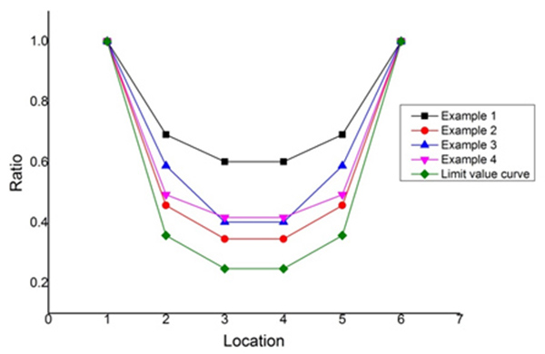
Obviously, it is safe and feasible to take equation (1) as the bearing point of the vertical stiffness limit curve.
The interval between columns is U, numbers of missing columns are n, and the equation of the vertical stiffness is shown in equation (2).
 |
(2) |
Due to the interval between columns are generally between 6 and 8 m, so this factor can be ignored. Define the following stiffness limit constant:
 |
(3) |
Substituting equations(3) in equations(2), the vertical stiffness of point x is formulated as follows:
 |
(4) |
4.2. Parametric Analysis of Equivalent Vertical Stiffness Theory
In order to highlight the contrast between the plan 1 and 2, the same parameters of plan 2 with plan1 is defined [12]. Obviously, if the value of B is too large, there will be little difference between the normal model and plan 2. If the value of B is too low, the assistant supporting system will continue to fall short of its stress. In this case, B has an upper and lower bound, to be chosen according to the stiffness of point x. Define the maximum value of vertical stiffness as 50000kN/m and the minimum value as 1000kN/m. Based on the interval [1000, 50000] kN/m, the upper and lower bound of B can be draw from above equations. In the span of 40m, 80m, and 120m, respectively, increase the number of missing columns and impose vertical spring constraint and horizontal hinge constraint at point x, furthermore, the upper and lower bound of B at different conditions can be obtain and the maximum numbers of missing columns for plan 2. Detailed parametric analysis plan is shown in Table 5.
| Number of Missing Columns | Span, m | ||
|---|---|---|---|
| 40 | 80 | 120 | |
| 4 | 7200-129600 | 7200-86400 | 7200-86400 |
| 6 | 20571-205710 | 20571-205710 | 20571-205710 |
| 8 | 44444-266664 | 44444-266664 | 44444-266664 |
For span 40m, general correlation between maximum stress ratio of local member and vertical stiffness is not obvious, and the same to the number of missing columns. The reaction provided by the assistant supporting system is mainly related to the vertical stiffness of the most edge missing columns and show little consistent with the number of missing columns. The basic rule is that the lower the vertical stiffness of the most edge missing column is, the less the reaction is provided by the assistant supporting system. The maximum displacement of structure is mainly related to the number of missing columns. The major trend is that the larger the number of missing columns and the smaller the stiffness of the assistant supporting system, the larger displacement of the structure. In the case of 80m and 120m span, results of members of the assistant supporting truss, maximum stress ratio, reaction and maximum displacement, are the same as the 40m, respectively.
Maximum stress ratio, reaction and maximum displacement of the assistant supporting truss’s members could show the change of structure’s mechanical performance. Minimum limit vertical stiffness B and matching vertical stiffness are chosen to be shown in Table 6.
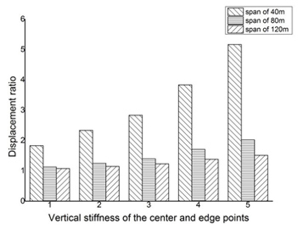
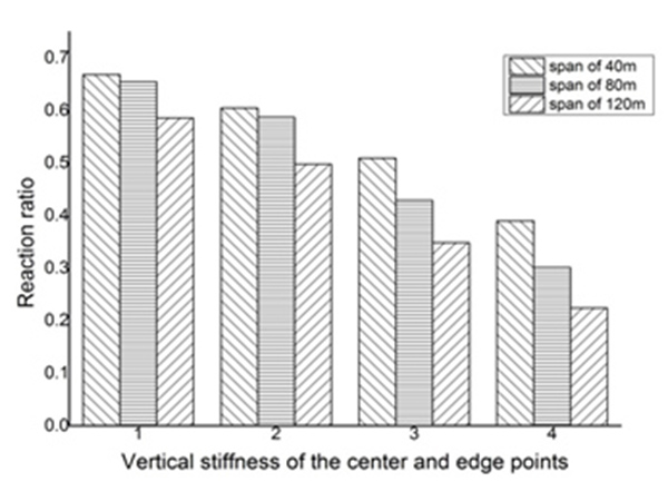
As shown in Figs. (11 and 12), through the comparison of three kinds of span displacement, when selecting an assistant supporting system with the same stiffness, reactions provided for suspended-dome have little difference at different span. However, the larger the span is, the smaller the change of displacement is. When the number of missing columns is the same, the smaller span of suspended-dome is more sensitive than the larger one. Therefore, a larger stiffness of the assistant supporting system is required when design the structure.
| Span, m | 40ˎ80ˎ120 | |
|---|---|---|
| number of missing columns | minimum limit vertical stiffness B | Corresponding vertical stiffness, kN/m |
| 4 | 43200 | 13500ˎ6000ˎ6000ˎ13500 |
| 6 | 123426 | 24000ˎ8640ˎ6000ˎ6000ˎ8640ˎ24000 |
| 8 | 266664 | 37500ˎ12245ˎ7407ˎ6000ˎ6000ˎ7407ˎ12245ˎ37500 |
4.3. Validation of Equivalent Vertical Stiffness Model
Define the stiffness of the most middle column of all missing columns by 6000kN/m. Considering safety, the stiffness provided by the assistant supporting system of the missing point should be greater than the limit value in Fig. (10). Given a suspended-dome as an example, which is 120m span and has 10 missing column. Applying the basic information into equations (3), the value of B can be shown as follows:
 |
Substituting B in equations (4) and the stiffness of all point can be calculated.
 |
 |
 |
 |
 |
Based on the design variables calculated formerly, a suspended-dome is designed to corroborate the equivalent stiffness theory. Keep the size of suspended-dome members and the prestressing force, through calculation and analysis, the maximum stress ratio is 0.987 and the maximum displacement is 163mm which located in the seventh ring. The load factor matching to the instability point is 4.24 in double nonlinear analysis and complies with the requirements of the design code.
CONCLUSION
In this paper, two kinds of feasible plans were proposed for suspended-dome with big partial holes. Through establishing and analyzing parametric models, the suitable range of the two proposed plans has been obtained.
(1) For plan 1, when the number of missing columns is not more than 2, this problem can be solved by adjusting members of the suspended-dome. However, the smaller the span is and the more missing columns are, the greater the missing columns impact on the overall stability is, and the possibility of causing local vibration is also greater.
(2) For plan 2, the relationship between suspended-dome and stiffness of the assistant supporting system is that the smaller the vertical stiffness is, the larger the stress ratio is. Furthermore, the smaller the vertical stiffness of the most edge column is, the smaller the reaction provided by the assistant supporting system. Besides, the greater the number of missing columns is, the smaller the stiffness of the assistant supporting system and the greater the structural displacement.
AUTHOR CONTRIBUTIONS
NC and RR designed the study; NC and RC performed the experiments and analyzed the data; NC, RC and RR wrote the manuscript.
ETHICS APPROVAL AND CONSENT TO PARTICIPATE
Not applicable.
HUMAN AND ANIMAL RIGHTS
No Animals/Humans were used for studies that are base of this research.
CONSENT FOR PUBLICATION
Not applicable.
CONFLICT OF INTEREST
The authors confirm that this article content has no conflict of interest.
ACKNOWLEDGEMENTS
Declared none.


