All published articles of this journal are available on ScienceDirect.

Stainless Steel Beam-Columns Behaviour
Abstract
There are several methods for considering the interaction between compression and bending for slender steel members. This is covered by the interaction formula and the general method, currently. For stainless steel, the structural design standards have been developed largely in-line and refer to carbon steel design guidelines. The current stainless steel interaction formula of axial force and bending moment given in EN 1993-1-4 was derived on limited results available. On the other hand, the general method may be used without any change for stainless steel according to the Eurocode despite the non-linear stress-strain behaviour, which obviously could lead to some drawbacks. Hence, the main objective of this paper is to compare the analysis results with existing Eurocode design formulas, the general method and some formula taken from experimental and parametric studies, showing their possible applicability, weaknesses and the need of further development. The conclusions are not applicable for stainless steel only, but they may be used for other non-linear materials such as aluminium alloys to some extent.
1. INTRODUCTION
Stainless steel is a specific high alloy steel of superb corrosion resistance but often designed also for its aesthetics appearance or when sanitary conditions apply. Development of design rules for stainless steel structural elements has been done mainly in the last two decades. It covers all the most important and basic types of loading such us bending or compression. However, no wide research was published for the members loaded by combination of both compression and bending which is very common loading case in the real structural members. The paper summarises possible design procedures and, based on a numerical parametric study, provides a recommendation of their use.
2. CURRENT METHODS OF BEAM-COLUMN BEHAVIOUR DESCRIPTION
The whole paper is limited to the interaction between major axis bending and axial compression of members subjected to major axis flexural buckling. So, the members are laterally and torsionally restrained along their length. Therefore, only the strong axis bending and buckling were considered (interaction factor ky, or kyy in EN 1993-1-1). Several methods of the behaviour description were published, with some of them not being directly related to stainless steel.
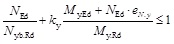
The beam-column interaction formula for stainless steel is given in the Eurocode EN 1993-1-4 [1]. The formula for the case of major axis bending and major axis flexural buckling may be written as:
 |
(1) |
 |
(2) |
where NEd is the axial force in the member;
Ny.b.Rd is the member resistance to axial compression with major axis flexural buckling;
My.Ed is the maximal major axis bending moment in the member given by the first order analysis;
My.Rd is the major axis bending resistance according to the section class;
eN.y is the shift of the neutral axis for the Class 4 sections.
The formula was developed around 10 years ago. Since then, more research has been done and published. Not exactly in the beam-column behaviour but in the material nonlinearity [2], which affects the interaction as well. Also, new stainless steel grades such as lean duplex steels or some ferritic steels were introduced for structural applications. The formula is simplified in neglecting the effect of moment distribution along the member. Therefore, for the members with non-uniform moment distribution along their length, conservative results could be expected. Also, the minimum value of ky = 1.2 may be conservative in the loading cases of dominant bending moment.
Together with the Eurocode for stainless steel, the current carbon steel rules [3] are also compared assuming both possible methods [4, 5] for members subjected to interaction of bending and compression.
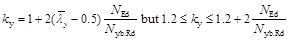
In the literature, the experimental program for beam-column members made for hollow [6] and open [7] sections was undertaken at VTT Finland by Talja and Salmi for austenitic and duplex steels. In the publication [6] a slight modification of ENV 1993-1-1 [8] interactive formula was suggested and it is also presented in this paper. In the original ENV 1993-1-1 procedure, the ky factor was limited to 1.5 whereas for the stainless steel members no limit was used. The formula can be therefore given as (3) and (4):
 |
(3) |
 |
(4) |
where βM.y is the moment distribution factor, for linear distribution of the bending moment βM.y = 1.8 - 0.7ψ
ψ is the ratio of the end moments.
More recently, ferritic hollow section beam-column tests were published by Arrayago et al. [9] and comparison to the design procedures showed their conservativeness.
For stainless steel section resistance under combined loading, an extensive experimental and numerical research was published by Zhao et al. [10, 11]. These show again a general conservativeness of the design standard procedures contributed to significant strain hardening of stainless steel. Also, Theofanous et al. [12] have investigated the section resistance before.
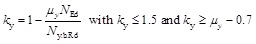
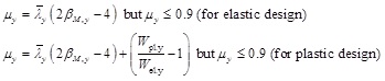
Among the numerical analyses published for the stainless steel beam columns, the most general proposal was published by Lopes, Real & Silva [13]. It is also derived from ENV 1993-1-1 procedure but with more significant change in μy coefficient.
 |
(5) |
Other numerical research was published by Greiner & Kettler [14] for stocky sections. Additionally the EN 1999-1-1 [15] design rules for aluminium alloys were compared. It was believed that these rules developed for non-linear stress-strain diagram may show reasonable results as well.
3. SHELL FE MODEL VALIDATION
A FE (finite element) model was made in software Abaqus. Four-node full integration shell elements S4 were used for the model of the open I sections and 9 nodes reduced integration shell elements S9R5 for the models of the square and rectangular hollow sections (SHS and RHS) respectively. The quadratic definition of the S9R5 element allowed more accurate corner geometry. The nodes of the end-sections were connected by rigid elements to their centroid. At that point, the axial load was applied on one end and the bending moment on both ends (if any). At both ends, the displacement was restrained but the rotation was free. The member was also prevented from the weak axis buckling along the middle of both flanges, which prevented possible torsion of the beam.
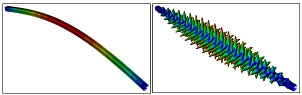
The fully non-linear (GMNIA, geometrically and materially nonlinear analysis with initial imperfections) analysis was performed. The initial imperfections were considered by the elastic buckling eigenmodes (Fig. 1). The amplitude for the global imperfection was L/1000 [16], where L is the pinned column length. For the local buckling, the amplitude b/200 was used, where b is the web width.
The residual stresses were neglected in all cases. As published before [17, 18], for the cold-rolled sections the influence of membrane residual stresses is negligible whereas the bending component of the residual stresses is inherently present in the stress-strain diagram. For stainless steel welded open-sections, no residual stress patter was generalised and more research would be needed. Using the same stress pattern as commonly used for carbon steel sections may be very conservative in the view of the new welding methods. However, if the FE model predicts the load capacity of column accurately (the effect of residual stresses is shown to be not very important), the effect of residual stresses is believed to be affected by this simplification even less.
The experiments from [6, 7] were used for the model validation (Table 1). The ratio between the FE model result and test result (separately for concentric and eccentric tests) is given.
| Section | Grade | σ0.2 | σu | n | Column slenderness | Concentric | Eccentric | |
|---|---|---|---|---|---|---|---|---|
| [MPa] | [MPa] | [-] | FEXP/FFEM | FEXP/FFEM | ||||
| SHS 60x60x5 | Class 1 | 1.4301 | 462.5 | 753.0 | 3.39 | 0.31 | 1.07 | 1.10 |
| 0.75 | 1.21 | 1.22 | ||||||
| 1.21 | 1.11 | 1.14 | ||||||
| 1.67 | 1.04 | 1.10 | ||||||
| RHS 150x100x3 | Class 4 | 1.4301 | 305.0 | 627.0 | 4.80 | 0.25 | 1.18 | 1.23 |
| 0.61 | 1.19 | 1.19 | ||||||
| 0.98 | 1.13 | 1.20 | ||||||
| 1.35 | 1.19 | 1.14 | ||||||
| I 80x10+160x6 (flanges + web) | Class 2 | 1.4301 | 300.0 | 620.0 | 6.00 | 0.40 | 0.97 | 0.91 |
| 0.69 | 1.00 | 0.96 | ||||||
| 0.96 | 0.98 | 1.03 | ||||||
| I 160x10+160x6 (flanges + web) | Class 2 | 1.4301 | 300.0 | 620.0 | 6.00 | 0.36 | 0.96 | 0.88 |
| 0.60 | 0.95 | 0.93 | ||||||
| 0.90 | 1.03 | 0.94 |
In the Table 1, the following characteristics used in the model are listed: σ0,2 is the yield strength, σu the ultimate strength, n the Ramberg-Osgood hardening exponent. The detailed information about the geometry and the material characteristics are given in [6, 7]. The higher resistance for hollow sections in the tests may be caused by neglecting the corner area with higher strength or by smaller imperfections. In general, the prediction of the FE model is reasonably accurate (7% underestimation of the load capacity in average) and the model was therefore accepted for the parametric study.
4. SHELL FE MODEL PARAMETRIC STUDY
The parametric study was made using the same sections as for the model validation, but with only one open section (I 80x10+160x6). The three selected profiles represent different section slenderness and section types. Three stainless steel grades (austenitic, ferritic and duplex) were considered. In compression, it resulted in the following section Classes (according to EN 1993-1-4):
- SHS 60x60x5 is Class 1 section for all stainless steel grades,
- RHS 150x100x3 is Class 4 for all stainless steel grades,
- I 160x80 is Class 1 (austenitic steel), Class 2 (ferritic) or Class 4 (duplex) depending on the stainless steel grade.
The material was defined by the yield and proof strength based on EN 1993-1-4. In fact, a significant over-strength should be expected, especially for austenitic steels. The material was defined by one stage Ramberg-Osgood stress strain diagram (6):
 |
(6) |
where n is the strain hardening exponent. This exponent was studied in detail by Afshan et al. [2] and the recommended values were used in this study (Table 2). The paper also noted that the initial modulus of elasticity E 0 for ferritic steel in the Eurocode (220 GPa) is overestimated and 200 GPa is therefore considered for all stainless steel grades.
| Material | Grade | E0 [GPa] | σ0,2 [MPa] | σu [MPa] | n |
|---|---|---|---|---|---|
| Austenitic | 1.4301 | 200 | 230 | 540 | 5.6 |
| Ferritic | 1.4003 | 200 | 280 | 450 | 7.9 |
| Duplex | 1.4462 | 200 | 480 | 660 | 7.2 |
The column was always pinned at both ends; the lateral and torsional buckling was prevented again. The major axis bending distribution was uniform along the member length (ψ = 1) for all sections. For SHS 60x60x5 of stainless steel grade 1.4301 also triangular (ψ = 0), and bi-triangular (ψ = -1) moment distribution was investigated. Three different column lengths were used.
The parametric study could be summarised as follows:
- SHS 60x60x5 (Austenitic, Ferritic, Duplex), ψ = 1, L = 1050, 1700, 2350 mm;
- SHS 60x60x5 (Austenitic), ψ = 0, L = 1050, 1700, 2350 mm;
- SHS 60x60x5 (Austenitic), ψ = -1, L = 1050, 1700, 2350 mm;
- RHS 150x100x3 (Austenitic, Ferritic, Duplex), ψ = 1, L = 2700, 4350, 6000 mm;
- I 160x80 (Austenitic, Ferritic, Duplex), ψ = 1, L = 3000, 6000, 9500 mm.
The value of the interaction factor ky was calculated using numerically (Abaqus FE model) estimated section resistance in compression and in bending as well. In addition, the compressive resistance in buckling and critical elastic buckling load were calculated by FE model. The comparison between the design formulae for all selected methods and the numerically established interaction factors are shown in Fig. (2) and in Table 3.
| EN 1993-1-4 | EN 1993-1-1 Method 2 |
EN 1993-1-1 Method 1 |
ENV 1993-1-1 | Talja-Salmi | Lopes et al. | Greiner-Kettler | Aluminium | |
|---|---|---|---|---|---|---|---|---|
| All cases considered | ||||||||
| ky/ky.FEM | 1.235 | 0.969 | 0.925 | 0.997 | 1.129 | 0.828 | 1.053 | 0.966 |
| Standard deviation | 1.012 | 0.472 | 0.315 | 0.215 | 0.282 | 0.140 | 0.937 | 0.524 |
| Uniform moment only | ||||||||
| ky/ky.FEM | 1.015 | 0.885 | 0.878 | 1.001 | 1.162 | 0.834 | 0.872 | 0.845 |
| Standard deviation | 0.180 | 0.171 | 0.158 | 0.218 | 0.286 | 0.131 | 0.193 | 0.153 |
The existing EN 1993-1-4 provision (1) and (2) showed reasonably good and mostly conservative results. However, as the formula is very simple and does not consider the influence of the moment distribution (as mentioned before), it is very conservative for the non-uniform moment distribution (ψ = 0 and -1). This is together with the minimal value of ky = 1.2, leading to conservative results for the cases where bending moment is dominant, the main limitation of the procedure.
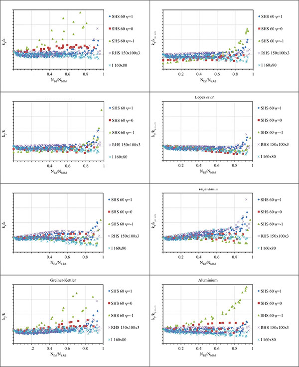
The EN 1993-1-1 methods showed lower scatter but most of the results were on the unsafe side. A similar conclusion was found for ENV approach.
Talja and Salmi`s formula (3) and (4) using the same expression just without upper bound for the ky factor predicts the interaction factor slightly better. The results are on the safe side in average. For slender section columns loaded mostly by the compressive force, the results are very conservative. However, the interaction factor is of lower importance in such cases as the bending moment is low. The method may be perhaps the most suitable among the all the methods investigated.
The procedure used in EN 1999-1-1 for aluminium alloy structures and method published by Greiner and Kettler showed good results in average, but they are very scattered for triangular and bi-triangular moment distribution.
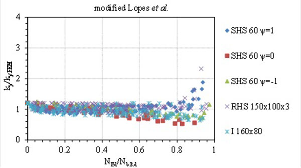
The method presented by Lopes et al. was found to be very unsafe. This is due to the different stress-strain diagram considered in the original analysis. The stress strain diagram from EN 1993-1-2 was used by the authors instead of the Ramberg-Osgood formula. However, as the scatter in the results was quite low, the method would be therefore easy for modification if ky is multiplied by 1.2 and the upper and lower bound for the ky omitted. The modified formula may be therefore given as (7):
 |
(7) |
The formula gives much better agreement, but it may be still unsafe in some cases. The results are unsafe especially for non-uniform bending moment distribution of members loaded by small bending (Fig. 3). Again, for the small bending moments, the variation in the interaction factor is less important because compression is dominant. The average value of ky/ky.FEM = is 1.00 and standard deviation 0.166 (all moment distributions compared). As was mentioned above, the minimal value of ky = 1.2 of the formula is in principle very conservative. The results were very similar for all considered stainless steel grades. However, the method tends to be generally unsafe for other than uniform moment distribution along the member (ψ = 0 and -1) and a deeper revision would be necessary.
For further possible modification of the EC3 Part 1-4 formula, more numerical results would be needed. Even more important would be to carry out more beam-column tests mostly for the case of small bending moments and dominant compressive force.
5. THE GENERAL METHOD OF EN 1993-1-1
The general method is an alternative method of EN 1993-1-1 based on GNIA, geometrically nonlinear analysis of structure with both sway and member imperfection. To the method, no limitation is given in the EN 1993-1-4 for stainless steel structures. Also the EN 1999-1-1 for aluminium alloys uses the method.
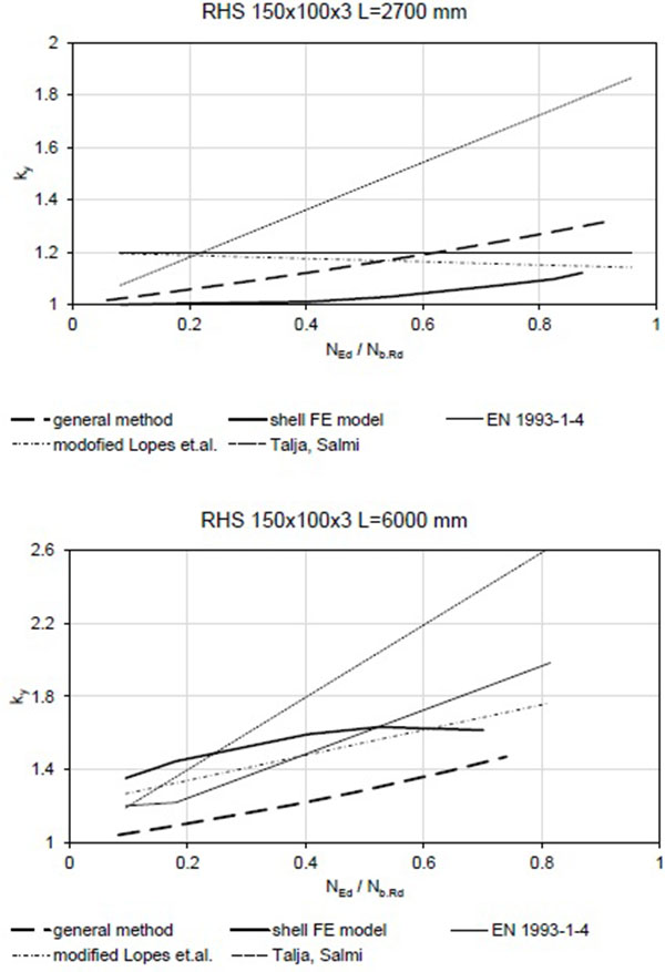
In the paper, a small example is shown for members compared with the shell element FE model. The comparison is made for two section types and two column lengths for each:
- RHS 150x100x3 (Austenitic), ψ = 1, L = 2700 and 6000 mm (= 0.50 and 1.11);
- I 160x80 (Austenitic), ψ = 1, L = 3000 and 9500 mm (= 0.51 and 1.59).
The members were modelled using beam elements B31 in software Abaqus again. The modelled members were pinned on both sides and lateral-torsionally supported along the whole length. The material is considered elastic with E0 = 200 GPa.
The FE section definition led to a small difference between the shell / beam model cross-sectional characteristics. For the open I section in the shell element model, the flange and web overlapped in some parts. Therefore, the flange of the section in the beam model was considered thicker to have the differences in the section area or second moment of area between the shell and beam model lower than 1%. Similarly, for the RHS the beam model formulation neglected the section corners. Again, the flange of the section for the beam model was therefore corrected (lowered) accordingly. The correctness of the procedure was later verified by calculation of the elastic buckling force which showed no significant difference (always significantly less than 1%) between the shell and the beam model.
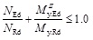
The initial equivalent geometric imperfection amplitudes e0 were calculated according to the buckling curve (Table 4) using formula (8). This led to amplitudes summarised in Table 5.
| Section type (flexural buckling) | α |  |
| Hollow sections | 0.49 | 0.4 |
| Open welded sections (buckling to the main axis) | 0.49 | 0.2 |
| Section and length of the member | e0 [mm] | e0 / L |
|---|---|---|
| RHS 150x100x3, L = 2700 mm | 2.211 | 1/1221 |
| RHS 150x100x3, L = 6000 mm | 15.977 | 1/376 |
| I 160x80, L = 3000 mm | 8.926 | 1/336 |
| I 160x80, L = 9500 mm | 41.282 | 1/230 |
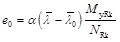 |
(8) |
where α and
are the characteristics of the buckling curve,
is the non-dimensional column slenderness,
My.Rk is the characteristic section resistance in bending to the major axis,
NRk is the characteristic section resistance in compression.
The member load-bearing capacity was defined by reaching the resistance of the section at mid-span (only uniform moment distribution was considered). The section resistance was defined as (9):
 |
(9) |
where NEd is the compressive axial force;
NRd is the section resistance in compression;
MyEdII is the bending moment calculated by GNIA;
My.Rd is the section resistance in bending to the main axis.
The model was firstly compared for being able to predict the compressive resistance of a column (no bending moment loading). With the difference between the shell and the beam model being around 4% in average, the model was accepted for further study. Later, loading by the bending moment was added and factor ky calculated from the formula (1).
The results are compared in Figs. (4 and 5). It can be seen that the general method underestimates the interaction between the compression and bending with exception of the short RHS 150x100x3 member which is subjected mainly to local buckling and the global (member) buckling is almost negligible.
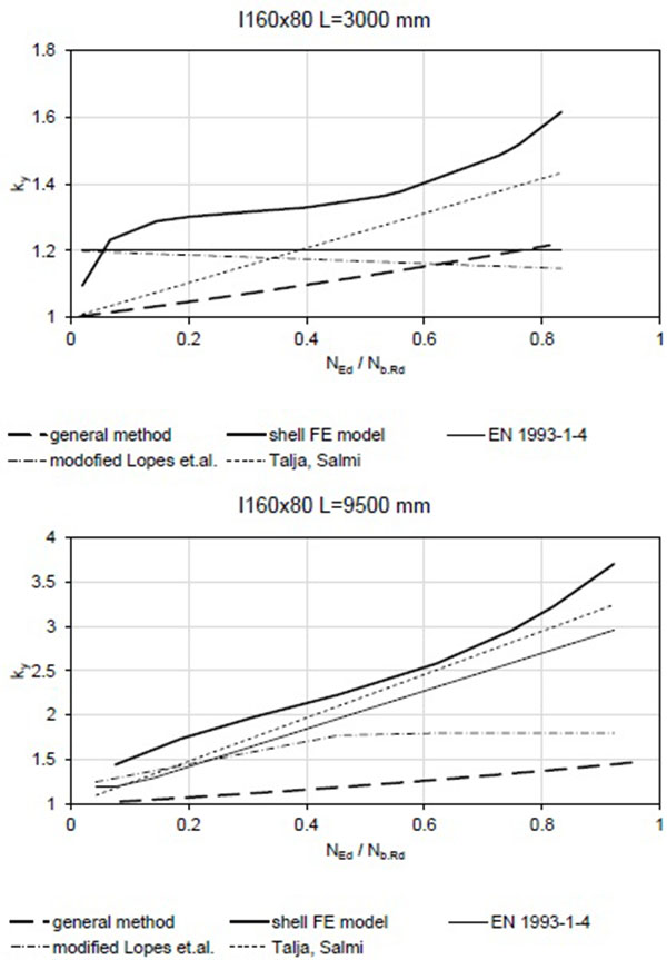
The lower increase in the bending moment is contributed to the fact of neglecting the material nonlinearity. That means the stainless steel member is losing stiffness progressively with the load increase. For column (no transversal load or bending) this is compensated by the equivalent geometric imperfection which covers the effect of the stress-strain diagram. However, it is not able to cover the effect of decreased stiffness caused e.g. by bending moment load.
Therefore, a reduced stiffness was considered in the following beam model. Firstly, the secant Elasticity modulus for stress level equal to the yield strength was tested (10):
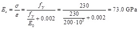 |
(10) |
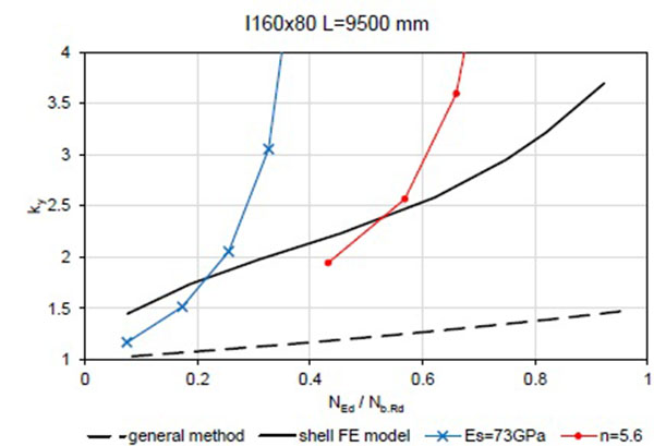
Secondly, the non-linear stress strain diagram was used represented by the Ramberg-Osgood diagram with the strain hardening exponent n = 5.6. The comparison is given in Fig. (6) for the open section I 160x80 of L=9500 mm.
Both of these modifications give a very conservative result. The secant modulus clearly underestimates the initial stage of the loading as well as the fact that some section fibres and some of the member sections are loaded lower and not even reaching the yield strength. The beam model considering the non-linear diagram also underestimates the resistance (overestimates the ky factor). This is because the effect of the non-linearity on column buckling is once present in the buckling curve, respectively in the equivalent geometric imperfections. The general method is recently not suitable for materials described by the non-linear stress-strain diagram.
CONCLUSION
The main objective of this paper is to study relevant interaction factors for stainless steel beam columns. The formula proposed by current or previous standards for steel structures (EN 1993-1-4, EN 1993-1-1, ENV 1993-1-1), some proposed by researchers [6, 7, 13, 14] and also the interaction formula for Aluminium alloy structural members (EN 1999-1-1) was considered and evaluated. The parametric and numerical study was carried out for three stainless steel grades (austenitic, ferritic and duplex grades), different section types (hollow and open section) and three column lengths.
Based on the individual interaction factors a comparison was made. It showed relatively good results in average for EN 1993-1-4 and the method is suitable for design of stainless steel structures. Nevertheless, especially for the case of non-uniform moment distribution along the member length, very conservative results may be expected. In addition, the conservativeness of the procedure for members loaded mostly by bending was shown.
Hence, considering the parametric and numerical study result, the modification of ENV 1993-1-1 proposed by Talja and Salmi [6] was found to be most suitable from all the methods. It was also suggested to modify and make some improvements of the formula published by Lopes et al. [13]. It showed the lowest scatter and was found to be simple to use. After the small modification, the observed values were good. To apply such formula for the design standard, further refinement would be needed, especially for the cases of significant bending moment and non-uniform moment distribution along the member.
Besides the comparison of the interaction factors, the general method was compared (GNIA) too. It was shown that when the initial Elasticity modulus E 0 is used, the interaction between the moment and compression is underestimated for the slender members. This may be compensated by reduction of the Elasticity modulus or by using the non-linear stress-strain diagram (GMNIA). However, with some conservativeness for members loaded by compression mainly as the equivalent geometric imperfection cover the effect of yielding already.
The GMNIA would be the most suitable method to be used if the equivalent geometric imperfections are reduced. With the equivalent geometric imperfections based on the buckling curve, conservative results may be expected for slender members loaded mostly by compressive axial force. However, the common engineering software is often lacking this material description and the method is for this reason not very practical now.
No new formula or method is proposed as the data, especially the tests, are very limited. However, the authors showed that further investigation of the stainless steel beam-columns would be necessary. It is believed, that similar conclusions may be found also for aluminium alloys as the stress-strain behaviour is almost identical.
CONFLICT OF INTEREST
The authors confirm that this article content has no conflict of interest.
ACKNOWLEDGEMENTS
Declared none.

