All published articles of this journal are available on ScienceDirect.

Nonlinear Performance of Extended Stiffened End Plate Bolted Beam-to-column Joints Subjected to Column Removal
Abstract
This paper presents a numerical study on the behavior of extended stiffened end plate bolted beam-to-column joints subjected to sudden column removal. To this aim, finite element analyses, validated against experimental tests available from literature, were carried out to investigate the response of the joints under catenary action. The influence of additional bolt rows, generally ineffective in case of design for pure bending response, was also examined and some practical design implications have been drawn up from the parametric study.
1. INTRODUCTION
In the last decades, the worldwide increase of terrorist attacks on civil structures and infrastructures led to an increasing interest in structural design for guaranteeing robustness against progressive collapse, which can be defined as the propagation of local failure from element to element leading at the end to the collapse of an entire structure or a disproportionately large part of it. This concept was early introduced after the failure of the Ronan Point building in London in 1968, which collapsed by means of a chain reaction induced by a gas explosion in a corner at the 18th floor, which produced the collapse of the corner bay of the building from top to bottom [1]. In light of this finding, building structures are considered poorly robust if the final failure state is disproportionately greater than the one initiating the collapse.
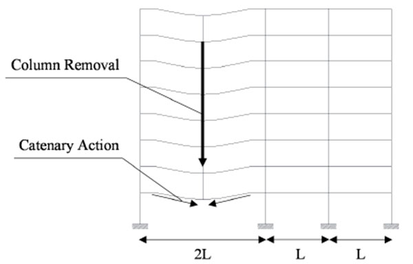
Nowadays, limited design requirements are recommended by existing building codes and, among those, ASCE 7-05 [2] recommends two possible approaches to design against progressive collapse, namely the direct and indirect method. The first approach is mainly based on the alternative load path approach (APM) that gives some regulations in order to avoid the propagation of the collapse from an element to the remaining parts of the structure. The direct method aims at providing sufficient strength to resist the failure at critical locations, e.g. a column loss scenario (Fig. 1) where an interior column has been removed (e.g. because of blast or impact) and an alternate load path develops through catenary action, which occur into the beams of the zone directly affected by the column loss with significant strain hardening and bending moments larger than the theoretical plastic bending strength [3-8].
More in detail, the guideline for progressive collapse mitigation issued by General Services Administration (GSA) of USA [9] provides a flow-chart methodology to determine whether constructions need to be verified against progressive collapse.
The U.K. building regulations [10, 11] are based on the tie force method (TFM) that required buildings be designed to resist disproportionate failure by tying together structural elements, adding redundant members and providing sufficient strength to resist abnormal loads. However, since TFM does not consider the dynamic amplification of tying force, this approach is unable to prevent the progressive collapse in steel frame buildings if low ductility connections are used [12], thus limiting the development of full catenary action.
The possibility to develop full catenary action plays a key role to ensure sufficient ductility and redistribution capacity after column removal scenario and, in case of steel buildings, the bolted beam–to-column joints are the more critical elements. Indeed, the joints are subjected to significant increase of forces (i.e. bending moment, shear and axial forces) under column loss, which are due to second order effects and catenary action developing into the connected beams. Therefore, the beam-to-column joints are prone to failure prior the connected members, as highlighted by experimental studies on both bare steel and composite steel-concrete beam-to-column assemblies comprising simple and moment joints [13-17]. With the aim at investigating the influence of the catenary effect in the response of beam-to-column joints and to improve detailing rules to enhance the joint performance, several numerical studies have also been recently carried out [18-25], examining the role of the out of plane pulling action, the yielding strain ratio, the beam depth over the column depth.
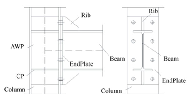
However, the behavior under catenary action in case of column removal (namely combined axial, shear and bending actions) of steel extended stiffened end plate (ESEP) bolted beam-to-column joints (Fig. 2) is not comprehensively investigated in literature.
ESEP joints are largely used for steel moment resisting buildings to withstand both seismic and wind actions in United States of America (USA) and Europe. Therefore, several studies have been carried out to investigate their behavior under both monotonic and cyclic pure bending [26-29] and design methods based on finite element analysis were also developed [30-34]. Moreover, in the USA this joint typology is seismically prequalified on the basis of recommendations developed within the SAC project and published as a series of FEMA documents [35, 36] and then been incorporated into the AISC341 [37] and AISC358 [38].
The lack of code requirements for robustness of ESEP joints motivates the study presented in this paper, which focuses on the influence of design detailing (e.g. steel grade, bolt strength and increase of number of bolt rows) on the development of catenary action, and in which term second order bending moment due to catenary actions affects the joint ductility. To this aim, parametric analyses based on finite element models (FEM) were carried out. The effectiveness and accuracy of modelling assumptions were validated against experimental results available from literature [26]. As described hereinafter, the paper is organized in three main parts, namely: i) the modelling assumptions and validation against test results; ii) parametric study; iii) discussion of the results.
2. Finite Elements Analysis
2.1. Modelling Assumptions and Calibration
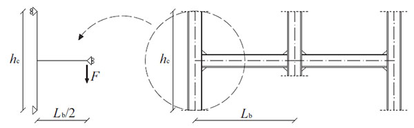
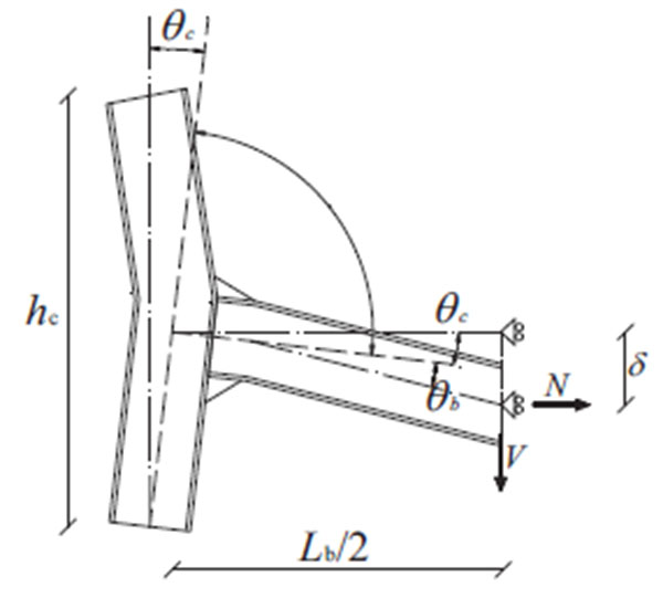
Finite element models (FEMs) were developed using ABAQUS v.6.13 [39]. The geometry of the numerical models for parametric study (beam and column length, boundary conditions) was obtained considering the sub-structuring described in Fig. (3). Both geometrical and mechanical nonlinearities were accounted for.
The finite element type C3D8I (an 8-node linear brick, incompatible mode) was adopted for steel beams, columns and high strength bolts. This element was selected because it can effectively avoid shear-locking phenomenon (comparing with element C3D8R), which could significantly affect the initial stiffness of connection.
Steel yielding was modelled by means of the von Mises yield criteria. Plastic hardening was represented using a nonlinear kinematic and isotropic hardening on the basis as described by [33, 34].
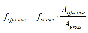
Bolts were modeled by meshing their shank as a solid cylinder having the nominal circular gross area of the bolt [34]. In order to simulate the bolt strength using its nominal shank area, the material stress was scaled as follows:
 |
(1) |
where feffective is the effective stress, factual is the actual stress, Aeffective is the area of the threaded region and Agross is the gross cross section of the shank.
This assumption is necessary because the strength of the bolt shank depends on its threaded part [40], which has an effective area that is noticeably smaller than its nominal gross area.
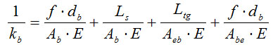
As for the strength, the elastic stiffness of the shank is affected by the threaded part. Therefore, the elastic modulus of the equivalent material constituting the shank was scaled in order to match the bolt stiffness calculated as follows [41]:
 |
(2) |
Where f is the stiffness correlation factor assumed equal to 0.55; db is the nominal diameter of the bolt; Ab is the nominal area of the bolt shank; Abe is the effective area of the threads; Ls is the shank length; Ltg is the length of the threaded portion included in the bolt's grip; and E is the actual modulus of elasticity of steel.
The external restraints were simulated by slaving to reference points (RP) the nodes belonging to the end cross sections of the beam and column. The following boundary conditions were considered:
- − RPs at both column ends have all the translational degrees of freedom and the rotation around the axis of the column fixed;
- − Constraints that avoid the rotation around the beam axis and the lateral out of plane displacement of the section were modelled;
- − At the end of the beam the displacement history was imposed as shown in Fig. (3).
The behaviour of full penetration welds was modelled by introducing internal tie constrain, thus linking together two separate surfaces. A tie constraint was also adopted to model the interaction between the continuity plates and column and web additional panels and column.
The clamping force simulating the tightening of bolts was applied in the middle face of bolt shanks using “Bolt Load” command.
Surface-to-surface contact interactions were used assuming the surface of the stiffer part as the master surface. Moreover, “Coulomb friction” was used in order to describe the tangential behaviour with a friction coefficient equal to 0.4, while “Hard contact” was selected to characterize the normal behaviour.
Quasi-static dynamic implicit analyses were performed and the loads were applied in two steps. Bolt pre-tension was applied as the first load case on the bolt shanks to obtain the equivalent pre-tension force. Afterwards, the monotonic displacement was imposed at the beam tip to generate a bending moment at the connection.
2.2. Validation of the FE Assumptions Against Experimental Tests from Literature
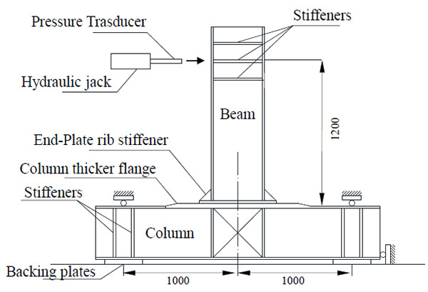
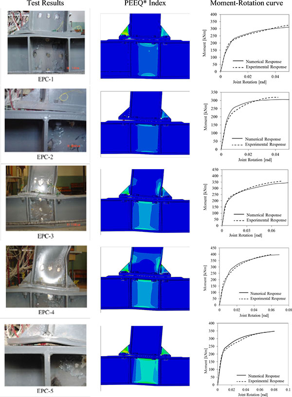
The FEM assumptions were calibrated against the experimental tests carried out by Shi et al. [26], which tested a set of five ESEP joints that were designed to investigate the influence of geometry of the end plate and the bolts on failure mechanism under pure bending moment (Fig. 4).
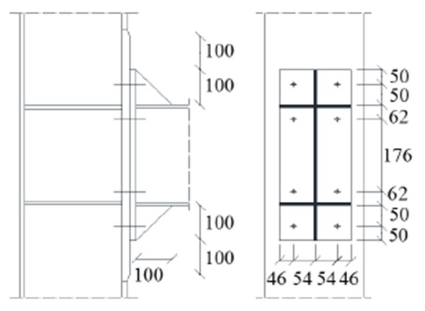
The geometrical details of the joint assemblies are given in Fig. (5), where it can be observed that the end plate is extended on both sides and the column flange is stiffened, the thickness of the continuity plates and the ribs are equal to or larger than the thickness of flange and web of the beam, respectively. In addition, the column flange thickness is equal to the thickness of the endplate in the connection zone only. Both beams and columns are made by welded built up profiles. Full penetration end plate-to-beam welds were adopted, while fillet welds were used for the remaining parts with depth equal to 8mm.
Table 1 reports the values of thickness of end plate and the bolt diameters of each tested specimen, while Table 2 summarizes the material properties of plates and bolts constituting the joint assemblies. The measured slip coefficient between the end plate and the column flange was equal to 0.44.
| Specimen | End-plate thickness | Bolt diameter |
|---|---|---|
| [-] | [mm] | [mm] |
| EPC-1 | 20 | 20 |
| EPC-2 | 25 | 20 |
| EPC-3 | 20 | 24 |
| EPC-4 | 25 | 24 |
| EPC-5 | 16 | 20 |
| Specimen | Yield strength | Tensile strength | Elastic Modulus | Bolt Pre-tension force |
|---|---|---|---|---|
| [-] | [MPa] | [MPa] | [MPa] | [kN] |
| Steel (t<16mm) | 391 | 559 | 190707 | - |
| Steel (t>16mm) | 363 | 537 | 204228 | - |
| Bolts (M20) | 995 | 1160 | - | 185 |
| Bolts (M24) | 975 | 1188 | - | 251 |
Table 3 reports the ratios between the axial plastic strength of the beam resistance and the tensile strength of all bolts (NBeam/Nbolt), the ratio between the beam plastic bending moment and the joint resistance (MBeam/MJoint), and the failure mode predicted by means of component method according to EN1993:1- 8 [42]. These ratios show that these joint assemblies can develop catenary action being the tensile strength of bolts larger than the axial strength of the beam even though all joints are partial strength.
| Specimen | NBeam/NBolts | MBeam/Mjoint | Failure Mode |
|---|---|---|---|
| [-] | [-] | [-] | [-] |
| EPC-1 | 0.92 | 1.72 | Bolt/web panel in shear |
| EPC-2 | 0.92 | 1.65 | Bolt fracture |
| EPC-3 | 0.64 | 1.62 | Web panel in shear |
| EPC-4 | 0.64 | 1.61 | Web panel in shear |
| EPC-5 | 0.92 | 1.78 | Web panel in shear |
The comparison between numerical and experimental results is reported both in terms of joint moment rotation curves (i.e. considering the contributions from web panel and connection only as shown in Fig. (6) and distribution of PEEQ (i.e. the equivalent plastic strain). As it can be observed from Fig. (7), the numerical predictions accurately match both the experimental response curves and the failure modes. In addition, Table 4 gives a quantitative comparison in terms of bending strength and initial stiffness, showing an excellent agreement between the experimental and the simulated capacity.
| Specimen | Moment resistance | Elastic Stiffeness | Faliure mode | ||
|---|---|---|---|---|---|
| [-] | Tests | FEM | Tests | FEM | [-] |
| [kNm] | [kNm] | [kNm/rad] | [kNm/rad] | ||
| EPC-1 | 343.7 | 340.3 | 52276 | 52276 | Bolts fracture |
| EPC-2 | 322.1 | 318.7 | 46094 | 46097 | Bolts fracture |
| EPC-3 | 390.3 | 387.5 | 46066 | 46070 | Buckling of beam flange and web in compression |
| EPC-4 | 410.8 | 409.3 | 47469 | 47460 | Buckling of beam flange and web in compression |
| EPC-5 | 355.4 | 355.2 | 41634 | 41631 | Bolt fracture Buckling of end-plate rib stiffener |
3. PARAMETRIC STUDY UNDER COLUMN LOSS SCENARIO
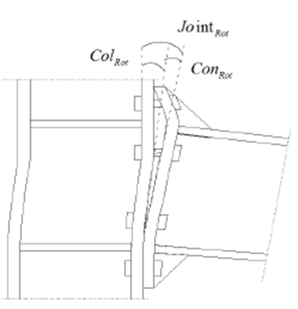
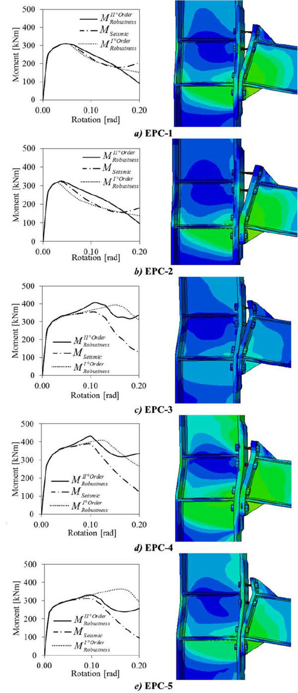
The investigated parameters are the steel grade of bolts and the influence of bolt row in the mid of end plate that is not adopted in seismic and wind resistant joints because of its negligible contribution under pure bending actions. The analyzed joint assemblies are those tested by [26] and two different loading scenarios were accounted for, namely: pure bending (i.e. seismic or wind scenario) and bending-axial force interaction (i.e. catenary action under column removal scenario). The numerical results are reported and discussed in terms of total moment rotation curves (where the rotations are considered from the axis of the column) and in terms of Von Misses Stress distribution. In addition, in case of column removal scenario, the joint flexural resistance (MII) is decoupled into first order bending moment (MI) and moment increase due to catenary second order (ΔM), which are calculated on the basis of free-body diagram shown in Fig. (8) as follows:
 |
(3) |
 |
(4) |
Where V is the vertical component of the applied force at beam tip and δ is the corresponding transverse displacement, while N is the horizontal component of catenary action and Lb is the beam length.
3.1. Catenary Action
As shown in Fig. (8), the development of the catenary action modifies the distribution of internal forces acting in the connection, which is subjected to a combination of bending moment, axial and shear forces. Since all examined joints have the same beam and column properties, the analyses showed that the axial force regime is mostly influenced by the stiffness and the strength of the connection.
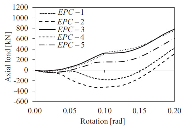
As it can be observed in Fig. (9), the shape of load-deflection response curve highlights that failure depends only on the strength and ductility provided by the bolted connection. Different main phases characterize the response curve owing to different resisting mechanisms activated at each stage. Indeed, the initial phase with zero axial force corresponds to the elastic behavior with small displacements and small deformations, namely where the first order response characterizes the joint behavior.
Subsequently, under large deformations axial forces start developing due to the effects of geometric nonlinearity in post-elastic range and the presence of axial restraints. During this stage, the connection is subject to bending moments and axial forces and different moment-rotation response curves can be observed depending on the mechanical properties of the connection zone, as depicted in Fig. (10).
It should be noted that at up to 0.04 radians the compression forces are activated in all joints due to the development of an arching effect, which transfers the lateral loads by the formation of a compression strut from the flange of beam tip to the compression center of the connection. However, at larger deformations the beam lengthening modifies the axial force regime from compression to tension in the most of cases, except for some joints (e.g. EPC-1 and EPC-2) that are characterized by increasing compression axial forces up to rotation of about 0.10 radians.
In particular, the analyses show that for those joints the beam is in elastic range but the plastic demand is concentrated into the stiffeners and the end plate connections with bolt failure (Fig. 7). EPC-1 and EPC-2 joints show also small difference between the response under pure bending and column loss scenario. Indeed, the arching effect does not allow developing the tensile catenary action.
Some differences are more evident when the rotations increase, thus influencing the second order moment, where the failure of bolts occurs without any prying action (mode 3 according to EN1993:1-8 [42]). It is interesting to note that those cases with compression axial forces are also characterized by an increased shear strength of the connection, which is resisted by friction between end plate and column face. Subsequently, the arching effect gradually decreases at larger rotation demand and the axial force becomes tensile.
In all cases, it was observed that increasing the beam axial tension force the bending effects become less significant and the connections undergo large tensile deformations. It should be also observed that the ductile behavior experienced by EPC-3, EPC-4 and EPC-5 joints is mainly due to the failure mode of equivalent T-stubs at bolt rows in tension. Indeed, those cases are characterized by mode 2 allowing the formation of prying action and larger rotation capacity prior bolt failure.
Therefore, under column loss scenario the following features of connection performance were observed:
- Increasing the joint rotation demand, the examined connections are subjected to considerable axial forces, which vary disproportionally to the bending moments depending on the strength and stiffness of the connection zone.
- Some components of the joint can be subjected to reversal of deformation due to the gradual decrease of arching effect to the development of full catenary action.
- Ductile response under tensile catenary action is observed where prying action occurs in the connection, namely for failure mode 2 of the equivalent T-Stubs at bolt rows in tension.
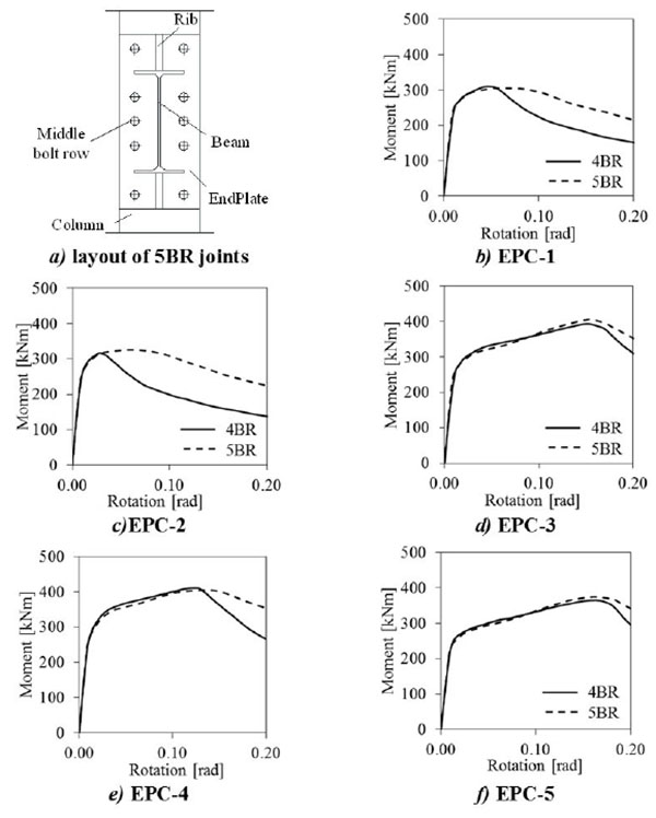
3.2. Influence of Bolt Row in the Middle of End Plate
The bolt row in the middle of end plate (namely in the horizontal axis of symmetry, see Fig. (11a) is generally missing in joints designed to resist pure bending actions, because its contribution to the flexural strength and stiffness is negligible. This is not the case of joints under column loss where catenary action develops. Indeed, the presence of this additional bolt row allows increasing the tensile capacity of the connection, thus increasing both the strength and the ductility.
Figs. (11) and (12) show the moment rotations curves under the two examined loading scenarios, respectively the pure bending and the column removal, either with or without the middle bolt row. The continuous lines refer to four bolt rows (4BR) joint configuration (i.e. without the middle bolt row), while the dashed lines identify the response curve of the joints with five bolt rows (5BR) (i.e. with the middle bot row).
As expected, in the case of pure bending (Fig. 11) the presence of a bolt row in the middle of connection does not increase the joint resistance, while it can improve the ductility in those joints characterized by mode 3 failure mode of the bolt rows in tension (e.g. EPC-1 and EPC-2). In the other cases, the presence of middle bolt row does not appreciably influence the response of those joints (e.g. EPC-3, EPC-4 and EPC-5), because it cannot modify the resisting mechanism of the weakest joint components.
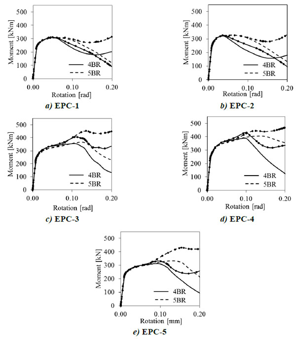
The beneficial influence of middle bolt row on joint response can be recognized under catenary action for rotation demand larger than 0.05 radians, as depicted in Fig. (12) where the moment rotation curves considering both first order (i.e. dashed and continuous line for 4BR and 5BR, respectively) and second order response (i.e. dashed and continuous line with markers) are plotted.
Whatever the type of failure mechanism under pure bending, the presence of middle bolt row increases both ductility and strength of the joints.
3.3. Influence of Steel Grade of Bolts
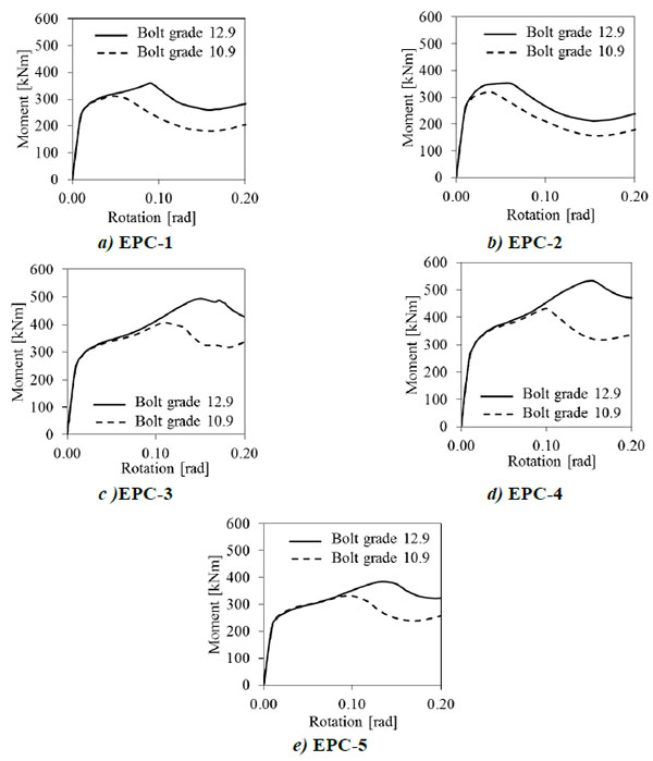
Since some joint assemblies are characterized by bolt failure under pure bending (i.e. mode 3 according to [42]), it was varied the bolt strength from 10.9 (i.e. the steel grade of bolts in the tests carried out by [26]) to 12.9 grade in order to evaluate its influence on the joint failure mechanism under robustness scenario.
Fig. (13) summarizes the numerical results showing a noticeable increase of both strength and ductility for all investigated joints, especially for EPC-1 and EPC-2 that are the assemblies designed with bolts as weak components of the connection. Indeed, stronger bolts allow developing prying forces that modify the mechanism of bolt rows in tension from mode 3 to 2, thus ensuring the development of the catenary action into the beam.
This beneficial effect is more significant for EPC-3, EPC-4 and EPC-5, where using stronger bolts allows concentrating the damage into the end plate (i.e. mode 1 according to [42]), thus enabling the larger rotation capacity.
CONCLUSION
The progressive collapse response of steel moment-resisting structures is strongly influenced by the performance of the beam-to-column joints. A numerical study about the response of extended stiffened end plate bolted beam-to-column joints under column loss scenario was carried out on the basis on FE model analysis validated against comparison with available experimental test results. The discussion of the obtained numerical results enabled to draw the following remarks:
- − The catenary action developing in the beam following the column removal significantly modifies the forces acting in the beam-to-column joint as respect to those induced by pure bending. Indeed, significant axial forces mobilize different type of mechanisms depending on the strength and stiffness of connection.
- − The compressive arching is the first mechanism that occurs into the beam under column loss. Subsequently, increasing the joint rotation demand, tensile catenary actions are activated by the lengthening of beam, but those effects become apparent at joint rotation larger than 0.05 radians.
- − The connection ductility is crucial to allow the development of catenary action.
- − In order to improve the joint performance is advisable to design connection with mode 1 and mode 2, which develop prying forces and concentrate the plastic demand into the end plate. Hence, the larger is the bolt strength, the better the joint performance under column loss scenario.
- − The introduction of an additional bolt row in the middle of the connection (namely in the horizontal axis of symmetry) is not effective for conventional loading (i.e. pure bending), but it substantially improves the joint performance in case of catenary action.
CONFLICT OF INTEREST
The authors confirm that this article content has no conflict of interest.
ACKNOWLEDGEMENTS
The research leading to these results has received funding from the European Union's Research Fund for Coal and Steel (RFCS) research programme under grant agreement no. RFSR-CT-2013-00021.
The Authors thanks also the financial support of the RELUIS project “Linea di Ricerca Acciaio & Composte Acciaio-Calcestruzzo” 2014-2015.

