All published articles of this journal are available on ScienceDirect.
Influence of Shear Connection Distributions on the Behaviour of Continuous Steel-concrete Composite Beams
Abstract
Background:
In this work the behaviour of continuous steel-concrete composite beams with different shear connection distributions obtained from two design methods, i.e. Eurocode 4 and a proposed alternative approach, is analysed.
Objective:
For this purpose a finite element model specifically developed for the nonlinear analysis of steel-concrete composite beams is adopted. This finite element model includes material nonlinearity of slab concrete, reinforcement steel, beam steel as well as slab-beam nonlinear partial interaction due to the deformable shear connection. The inclusion of the partial interaction in the composite beam model provides information on the slab-beam interface slip and shear force and enables to model the failure of the shear connectors.
Results and Conclusion:
In this way it is possible to analyse and quantify the effect of shear connector distributions on the global and local response of continuous steel-concrete composite beams, both under service load levels and at collapse. Particular attention is focused on the ductility requirements on the shear connectors when varying the connection design approach and distribution.
1. INTRODUCTION
Composite beams made by a steel beam connected to a reinforced concrete (RC) slab are widely adopted as a structural solution for building floors and bridge decks, owing to the many advantages arising from combining RC and steel, [1, 2]. Many structural features of steel-concrete composite beams related to their service state and ultimate state behaviour have thoroughly been investigated in the past, by using both experimental tests and numerical simulation. On the other hand, some other structural features deserve more attention since reduced information is available. Among the latter is the evaluation of the effects of different distributions of shear connectors on the global and local response of composite beams. In general, steel-concrete composite beams require specific attention to the design of their shear connectors and the relevant distribution of connectors along the beam span. The design should include not only the evaluation of the required strength of the shear connection but also its slip capacity compared to the slip demand at the ultimate limit state, [3-5]. At this regard, some recent results are available for simply supported composite beams [6] while no studies for continuous beams can be found in the technical literature. For this reason, the objective of this work is to study the behaviour of continuous steel-concrete composite beams with different shear connection distributions. In this way this work aims at providing a contribution to identify the relation between shear connection design (strength and distribution) and the structural behaviour of the designed composite beams. For this purpose a nonlinear finite element code [7] specifically developed by the authors for the analysis of steel-concrete composite beams and validated by comparisons with experimental tests [8] is adopted. This finite element model includes material nonlinearity of slab concrete, reinforcement steel, and beam steel together with the slab-beam nonlinear partial interaction due to the deformable shear connection. The inclusion of the partial interaction in the composite beam model permits to have information on the slab-beam interface slip and shear force. In addition, the partial interaction model enables to describe and include the potential failure of shear connectors. In this way it is possible to analyse and quantify the effect of shear connector distributions on the global and local response of continuous steel-concrete composite beams, both under service load levels and at collapse. Particular attention is focused on the ductility requirements on the shear connectors when varying the connection design approach and distribution.
2. SHEAR CONNECTION DESIGN IN CONTINUOUS BEAMS
The design of the shear connection in steel-concrete continuous composite beams is analysed and discussed in this study using a symmetric two-span continuous beam under uniform distributed load as reference structural configuration. Due to the symmetry of the structural problem being considered, only the first span is analysed (Fig. 1a). Various design methods for the shear connection can be employed to allow the transmission of forces between the steel girder and the RC slab required for developing a composite action mechanism [1, 2]. The problem is more complex than in simply supported beams for two main reasons. The problem is more complex than in simply supported beams for two main reasons: (i) the more complex nonlinear behaviour activated for increasing load levels, i.e., concrete cracking in the hogging region; (ii) the redistribution of the bending moment between hogging and sagging regions that can be significant, thus, modifying the tracts under compressions and under traction for increasing load levels.
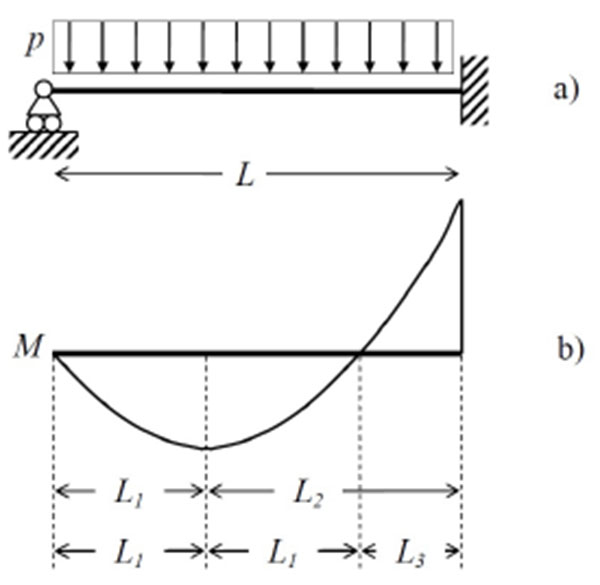
In the sequel two approaches are adopted, namely: (i) the approach proposed in Eurocode 4 Part 1 [9] for beams in which the plastic theory is used for evaluating the resistance of cross sections; (ii) an alternative approach based on alike considerations except for a different choice of the tracts in which longitudinal forces are balanced. In both approaches the effect of natural bond between steel girder and RC slab is neglected, as explicitly required by Eurocode 4 Part 1 [9].
3. SHEAR CONNECTION DESIGN ACCORDING TO EUROCODE 4
In the Eurocode 4 Part 1 design approach [9] two tracts are considered as defined by the bending moment diagram (Fig. 1b): a first tract of length L1 from the external support to the maximum sagging bending moment; a second tract of length L2 from the maximum sagging bending moment to the internal support. In the sagging cross sections the maximum longitudinal force N1 that the shear connection may possibly be required to transfer between the slab and the steel beam is given by:
 |
(1) |
Where Na is the plastic axial force of the steel beam in tension and Nc the ultimate axial force of the RC slab in compression. In the hogging cross sections the maximum longitudinal force N2 that the shear connection may possibly be required to transfer is given by:
 |
(2) |
where Ns is the plastic axial force of the reinforcement of the slab in tension having assumed null strength of the concrete in tension. A full shear connection must be able to develop the shear forces qs1 and qs2 so to satisfy the longitudinal balance conditions as depicted in Fig. (2):

 |
(3) |
 |
(4) |
With z the abscissa along the beam axis of a reference system having its origin in the left external support. If the shear connectors have sufficient deformation capacity, i.e., ductile shear connectors, then a uniform connection distribution along each tract can be adopted.
When full shear connection design is considered, according to Eurocode 4 Part 1 [9] it is possible to assume a uniform connection distribution along each tract if the characteristic slip capacity of the connector is at least 6 mm (paragraph 6.6.1.1 of Eurocode 4 Part 1), all critical sections in the span considered are in Class 1 or Class 2 (compact cross sections), the plastic resistance moment of the composite cross section does not exceed 2.5 times the plastic resistance moment of the steel member alone (paragraph 6.6.1.3 of Eurocode 4 Part 1).
4. ALTERNATIVE SHEAR CONNECTION DESIGN
An alternative design approach is here presented for comparative purposes. Three tracts are considered (Fig. 1): a first tract of length L1 from the external support to the maximum sagging bending moment; a second tract of length L1 from the maximum sagging bending moment to the point of null bending moment; a third tract of length L3 from the point of null bending moment to the internal support. A full shear connection must be able to develop a shear force qs1 in the first two tracts (total length 2L1) satisfying the longitudinal balance condition in the sagging region given by Eq. (3), and a shear force qs3 in the third tract satisfying the balance condition in the hogging region (Fig. 3):

 |
(5) |
It is observed that the first two tracts are the same used in the design of the shear connection in a simply supported beam of length 2L1 while the third tract is the only responsible to transmit the longitudinal shear between the steel beam and the RC slab in the hogging region. Given that the capacity of the RC slab in tension is limited, small quantities of shear connectors are expected when this alternative design approach is adopted. Regarding the distribution of the shear connectors in each tract, it is assumed that the prescriptions of Eurocode 4 Part 1 [9] commented in the previous section keep their validity also in the alternative design approach.
5. CASE STUDY DESIGN
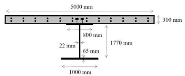
The two approaches considered in this study are adopted for the design of different shear connection distributions in a symmetric and symmetrically loaded two-span continuous beam having the cross section shown in Fig. (4) and kept constant along the two spans of length L = 40 m. The 5000 × 300 mm2 concrete slab (concrete compressive strength fc = 35 MPa) is reinforced with reinforcements of area As,top = As,bot = 7797 mm2 in the top and bottom layers (reinforcement yield stress fys = 500 MPa and collapse stress fts = 540 MPa), respectively, with a concrete cover of 30 mm. The steel beam (yield stress fya = 355 MPa and ultimate stress fta = 510 MPa for thickness less than 40 mm, yield stress fya = 335 MPa and ultimate stress fta = 490 MPa for thickness larger than 40 mm) has a 1770 × 22 mm2 web, a 800 × 65 mm2 top flange and a 1000 × 65 mm2 bottom flange. Composite cross sections are compact according to Eurocode 4 Part 1 classification and the plastic resistance moment of the composite cross section does not exceed 2.5 times the plastic resistance moment of the steel member alone. It is supposed that the continuous beam of this case study is realized using propped construction, i.e., additional supports are introduced in the steel beam before concrete slab casting and removed when concrete reaches its design strength so that the composite beam carries the entire structural self-weight load.
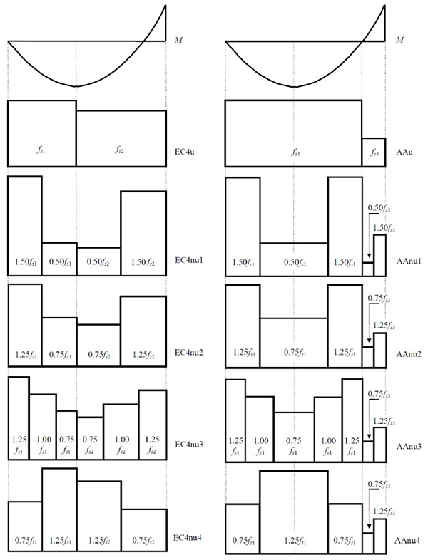
The shear connectors considered in this study have an assumed ultimate slip sult = 6 mm and, thus, they can be considered as ductile connectors according to Eurocode 4 Part 1 [9]. As already commented, according to Eurocode 4 ductile connectors may be spaced uniformly over each design tract. Assuming that the connection is fully plasticized (i.e., uniform distributions of qs1, qs2 and qs3), the connection strengths for the three tracts are given by fs1 = N1 / L1, fs2 = (N1 + N2) / L2, fs3 = N2 / L3 respectively. Considering the bending moment distribution at collapse as computed from plastic analysis (i.e., sagging and hogging moment hinges develop the full positive and negative plastic moments respectively), the tracts defined in Fig. (1) are L1 = 17 m, L3 = 6 m, and L2 = L1 + L3 = 23 m. Consequently the designed connection strengths for uniform connection distributions are fs1 = 3072.94 kN/m and fs2 = 2610.30 kN/m in the tracts of length L1 and L2 (EC4); fs1 = 3072.94 kN/m and fs3 = 1299.50 kN/m in the tracts of length L1 and L3 (alternative design). The relevant shear connection distributions for the two design approaches considered in this study are indicated as EC4u and AAu, respectively. Because of the ductility of the shear connectors, an arbitrary connection distribution for each design tract may be employed, provided that limits in maximum and minimum spacing of connectors are satisfied [9]. Feasible connection distributions different from the uniform distribution are considered in each tract for each design approach, as shown in Fig. (5). When the design according to Eurocode 4 is considered, the shear connection distributions indicated with the suffix nu1, nu2, and nu3 have a stronger connection at beam ends where the vertical shear is larger. On the other hand the distributions indicated with the suffix nu4 have a weaker connection at beam ends while the connection is stronger in the region where the sagging bending moment is larger. Similar considerations apply to the two non-uniform distributions designed following the alternative approach, with the difference that the connections in the hogging regions are always stronger near the support where both vertical shear and bending moment are larger.
6. NUMERICAL MODEL
The nonlinear behaviour up to collapse of the designed steel-concrete continuous composite beams are studied by using a material-nonlinear beam model with partial interaction where two Euler-Bernoulli beams in small deformation, one for the steel beam and one for the RC slab, are coupled by an interface model with a continuously distributed bond, allowing interlayer slip and enforcing equal vertical deflection and rotation between the steel and concrete components [7]. Numerical solutions are obtained through assemblies of a 16 degree of freedom (DOF) finite element, previously validated against a wide range of experimental tests, shown to provide accurate predictions of the experimental behaviour up to collapse and good numerical efficiency in terms of convergence for both local and global response quantities [8].
The adopted composite beam model requires a uniaxial constitutive law for the concrete slab to relate normal stresses to axial strains, a uniaxial constitutive model for the steel reinforcements in the slab to relate normal stresses to axial strains, a uniaxial constitutive law for the steel component to relate normal stresses to axial strains, and a shear connection constitutive model. In this study the Saenz nonlinear law is adopted for concrete under compression while null strength is assumed in tension [7]. An elastic - perfect plastic - hardening constitutive law [7] is utilised for the reinforcing bars embedded in the concrete slab with elastic modulus Ea = 200 GPa, hardening strain εhs = 0.02 and ultimate strain εults = 0.10. A bilinear elastic - plastic constitutive model [7] is adopted for the steel beam with elastic modulus Ea = 200 GPa, hardening strain εha = 0.04 and ultimate strain εulta = 0.11. Since fibre integration of the cross section stresses is used, different steel properties for web and flanges can easily be considered. No effects of local and global instabilities are included, thus, materials can fully develop inelastic deformations up to their ultimate strain. The adopted shear connection constitutive model is the Ollgaard et al. [10] relationship, an empirical equation providing good approximation of experimentally measured load-slip curves regardless of the failure mode, i.e. concrete failure in the region of the shear connectors, failure of steel studs, or combined failure of both. Its equation and analytical details are provided considering their importance for the purpose of this study:
 |
(6) |
where s is the slip between the two components of the composite beam, ps is the value of the shear force corresponding to s, fs is the connection shear strength (determined as the smaller value between the force causing failure in the concrete slab and the force causing failure of the connector), α and β are parameters controlling the stiffness (slope of the curve) for small and intermediate (of the order of β−1) values of the slip, respectively, and sgn(…) is the sign function. The curve in Eq. (6) tends asymptotically to the rigid-plastic model for α approaching zero. Since the stiffness at the origin is infinite when α < 1, the exponential law is substituted with a linear segment (with stiffness ka) from the origin to an assigned slip sa = 0.01 mm (with sa < β−1) to avoid numerical problems. The shear connection is supposed to have infinite ductility to evaluate the maximum expected slip demand. More details and examples of applications of the adopted constitutive laws can be found in [7, 8, 11], the latter study including the analysis of the influence of the material parameters on the structural response by means of sensitivity analysis.
7. NONLINEAR ANALYSIS PROTOCOL
In this study, given that the beams considered in the parametric analyses are designed according to Eurocode 4 [9], the nonlinear analyses are performed according to the indications of the Eurocodes for the nonlinear analysis of composite steel-concrete structures, i.e. paragraph 5.4.3 of Eurocode 4 Part 1 [9], paragraph 5.4.3 of Eurocode 4 Part 2 [12], paragraph 5.7 of Eurocode 2 Part 1-1 [13], paragraph 5.7 of Eurocode 2 Part 2 [14], and paragraph 5.4.3 of Eurocode 3 Part 1 [15]. According to these recommendations, the structural model must include all relevant failure modes and the nonlinear behaviour of the materials (concrete, steel of reinforcements, constructional steel, shear connectors) must be described by the mean values of their constitutive properties. The model should include the behaviour of the shear connection, necessary to realistically evaluate the shear connection slip demand, while it does not have to rely on concrete tensile strength as a primary load resisting mechanism. The nonlinear analysis is performed with loads increased from their serviceability values by incremental steps, so that the value of γGGk and γQQk are reached in the same step, where Gk and Qk denote the characteristic values of permanent and variable actions [16], respectively, and γG and γQ are the partial factors for permanent and variable actions, respectively (in buildings γG =1.35 and γQ = 1.50 in locations where loads are unfavourable while γG = 1.00 and γQ = 0 where loads are favourable [17]). From this point, the incremental loading process is continued until load qud is reached, at which, based on the Eurocode definition, one region of the structure reaches the ultimate strength or there is global failure of the structure. An example of application of such nonlinear analysis protocol to steel-concrete continuous composite beams can be found in [18] while approaches for more advanced treatments of the uncertainties in the response of steel-concrete composite beams can be found in [19].
8. DISCUSSION OF RESULTS
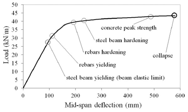
The ultimate load, ultimate mid-span deflection and maximum absolute value of the slip between slab and steel beam are given in Table 1. It is observed that the flexural bearing capacity is almost the same for all beams, with differences between and lower and largest collapse loads smaller than 1%. Differences are more noticeable for the mid-span deflection at collapse, with variations between the lower and largest deflection values of about 7%. It is observed that the beams with stronger connections where the sagging bending moment is larger (EC4nu4 and AAnu4) have the largest ultimate loads and ultimate deflections. These observations translate in differences in the global behaviour that can be hardly noticed when the load versus deflection curves are observed. One of such curves is reported in Fig. (6) for the case of beam EC4u.
| Beam | pult (kN/m) | vult (mm) | |s|max (mm) |
|---|---|---|---|
| EC4u | 43.37 | 580 | 1.61 |
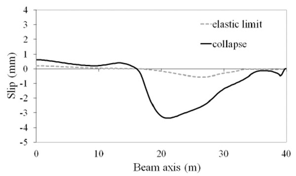
| EC4nu1 | 43.14 | 555 | 3.37 |
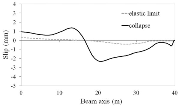
| EC4nu2 | 43.28 | 585 | 2.32 |
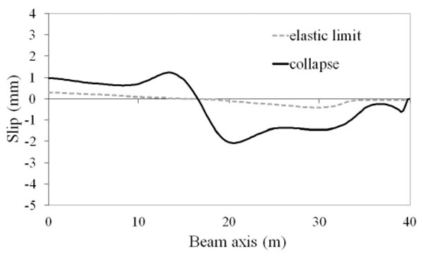
| EC4nu3 | 43.28 | 575 | 2.08 |
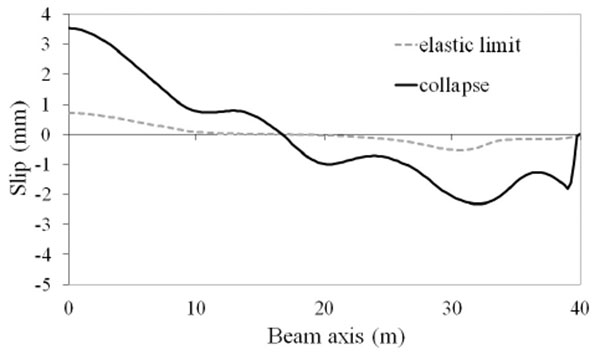
| EC4nu4 | 43.45 | 596 | 3.52 |
| AAu | 43.42 | 585 | 3.82 |
| AAnu1 | 43.21 | 585 | 2.34 |
| AAnu2 | 43.35 | 585 | 2.85 |
| AAnu3 | 43.28 | 575 | 2.87 |
| AAnu4 | 43.46 | 595 | 4.78 |
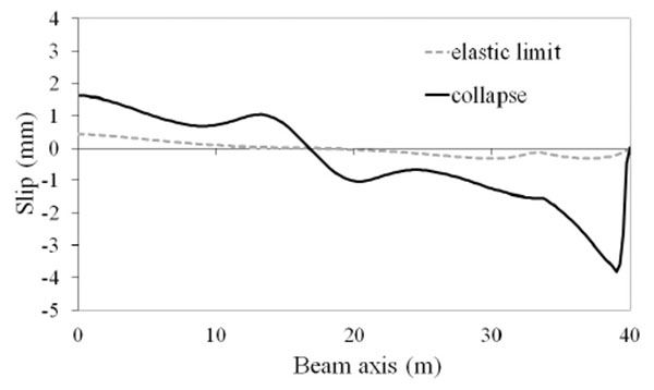
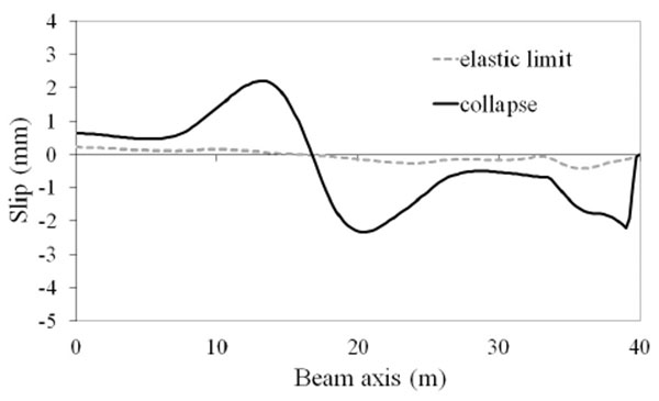
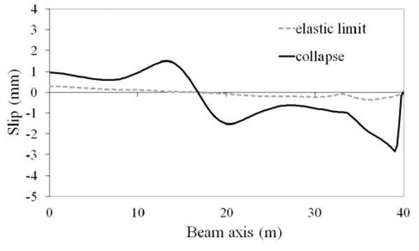
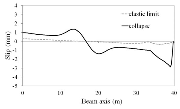
Much more significant differences in the tested beams are observed in the slip demand. Fig. (7-16) show the distributions of the slip between the slab and the steel beam for two conditions: composite beam at the elastic limit taken as representative of the maximum slip requirements at service state; composite beam at collapse where the maximum slip demand is reached. It is observed that there are differences of almost 3 times between the beam with lower slip demand (EC4u reported in Fig. 7) and the beam with larger slip demand (AAnu4 reported in Fig. 16). It is also observed that in all tested beams the ultimate slip of the shear connectors (sult = 6 mm) is not reached, thus, the connection is not responsible for beam failure.


CONCLUSION
In this study the behaviour of continuous steel-concrete composite beams with different shear connection distributions was analysed by mean of a specific composite beam model with partial interaction and including the nonlinear behaviour of materials and shear connection. In this way this research aims at providing a contribution to identify the relation between shear connection design (strength and distribution) and the structural behaviour of the designed continuous composite beams, a structural problem where very few information is available in the technical literature. The numerical response results presented for two-span continuous steel-concrete composite beams designed for full shear according to Eurocode 4 as well as according to a proposed alternative approach and adopting different shear connection distributions, show that the shear connection distribution has a significant influence on the slip demand with variations between the maximum slip requirement of about three times. On the other hand, the different shear connection designs and distributions considered do not translate in appreciable differences in the global behaviour of the continuous composite beams as for example described by the load versus deflection curves. Finally, it is commented that the proposed alternative design approach provides designs able to fully exploit the shear connection deformation capacity while the critical composite cross sections undergo plastic deformations up to their collapse.
CONFLICT OF INTEREST
The authors confirm that this article content has no conflict of interest.
ACKNOWLEDGEMENTS
The authors thank the anonymous reviewers for their constructive comments.


