All published articles of this journal are available on ScienceDirect.
Seismic Behavior of Concentrically Braced Steel Frames with Out-of-Plane Offset Irregularity
Abstract
Braced steel frames are sometimes designed with out-of-plane shifted bracing members on the first story due to architectural or functional considerations. Such frames are classified and designated as frames having the Type-4 horizontal structural irregularity entitled “frames with out-of-plane offset irregularity” as per the Minimum Design Loads for Building and Other Structures (ASCE 7-10). The purpose of this study is to investigate the nonlinear seismic behavior of ordinary steel concentrically braced frames with out-of-plane offset irregularity and evaluate their seismic design parameters. To this end, two 3-story and 6-story three-dimensional ordinary concentrically braced frames (OCBFs) with and without out-of-plane offset of one of the vertical elements on the first story were considered (i.e. irregular and regular configurations). The seismic design parameters considered in this study includes: frame overall overstrength factor, column overstrength factor and the inelastic dynamic inter-story drift demands. Nonlinear time-history dynamic analysis of the frames showed that overall overstrength factor of the low- and mid-rise irregular frames studied in this research is lower than that of the regular ones. Moreover, it was found that the Seismic Provisions prescribed overstrength factor (i.e. Ωo=2.0) to amplify columns axial seismic forces in OCBFs is not conservative for the studied regular frames’ columns as well as the columns in the vicinity of the shifted bracing members on the first story of the irregular frames. Also, it was shown that the studied low- and mid-rise regular and irregular concentrically braced frames experience greater inter-story drift demands than predicted by the amplified elastic analysis proposed in the codes.
1. INTRODUCTION
During the past earthquakes around the world, it has been observed that building frames having irregular configurations damaged severely compared to the regular ones. There are different types of irregularities (i.e. stiffness, mass and strength) in building frames design which may noticeably affect their desired regular and predictable response to seismic loads. Analytical and experimental investigations have identified different aspects of irregular frames’ response taking into account their displacement and ductility demands in the vicinity of irregularity levels. Seismic demands distributions for frames with different irregularity are not the same. Furthermore, uncertainty in seismic demands and capacity of complex structural systems with various configurations make it difficult to evaluate the behavior and response of such structures. Hence, not only the effects of irregularities in distribution of mass, stiffness, strength and combination of them should be considered in a seismic design but also there are some geometrically irregular configurations and specific structural features (e.g. discontinuity in lateral force resisting system-LFRS) which should be investigated.
Concentrically braced steel frames (CBFs) are commonly used as lateral force resisting systems (LFRSs) in earthquake prone areas. In order to satisfy architectural considerations or to provide openings or parking lot entrances on the first story, such frames are sometimes designed with out-of-plane shifting the bracing members to the adjacent parallel frames. In other words, the braced panels are not aligned vertically from the first story to the second story. Most of the international codes recognize such frames as frames with plan structural irregularity. For example, the Minimum Design Loads for Building and Other Structures, ASCE 7-10 [1] classifies and designates such frames as frames having the Type-4 horizontal structural irregularity entitled “frames with out-of-plane offset irregularity”. To estimate seismic demands of frames not exceeding 160 ft (48.8 m) in structural height and having horizontal irregularity of Type 4, the equivalent lateral force (ELF) analysis procedure is permitted as per ASCE 7-10 [1]. Moreover, columns supporting the discontinuous bracing span in such irregular frames must be designed to resist the seismic load effects including overstrength factor (i.e. amplified seismic loads) as per ASCE 7-10 [1]. However, it seems that the irregularity may alter the dynamic properties, height-wise distribution of base shear and hence columns axial demands of such irregular frames compare to the regular ones.
In the literature there are many studies (among others: Moehle [2]; Valmundsson and Nau [3]; Ali and Krawinkler [4]; Das and Nau [5]; Chintanapakdee and Choprs [6]; Tremblay and Poncet [7]; Michalis et al. [8]; McCrum and Broderikh [9]) on the seismic behavior of structures with mass, stiffness and strength irregularities. However, there are just few studies on the behavior of frames with discontinuous LFRSs as follows.
Imperial County Services Building located in El Centro, California, was a real example of such vertically discontinuous buildings that severely damaged by the 1979 Imperial Valley, Richter magnitude 6.4, earthquake. This reinforced concrete structure comprising a five story box-like and relatively rigid building was supported on columns and irregularly placed (offset) shear walls at the first story level [10]. Severe damage was experienced by the columns at the east end of the building with bursting of the rebar ties and concrete crushing resulting in significant shortening. Kreger and Sozen [11] studied experimentally the causes of column failures in this building and stated that these failures are due to large axial forces generated by the discontinuous shear wall system used for the building. Koohi [12] investigated the elastic behavior of steel frames with scattered bracing panels. He concluded that scattering the bracing panels reduces the frames lateral drifts. In order to study the inelastic behavior of vertically discontinuous CBFs, Shalchi [13] analyzed a 10-story CBF with six different bracing panel configurations using dynamic analyses and showed that the maximum displacement of irregular frames are smaller compared to the regular one’s.
In order to estimate the required strength of deformation-controlled members (e.g. columns) in seismic design of CBFs, the earthquake induced axial load of such members based on ELF analysis must be multiplied by the corresponding overstrength factor (i.e. 2.0). The main reason of considering this amplified axial load is to estimate the maximum expected seismic axial load demands in such members’ design to remain in elastic range. Richards [14] investigated seismic column demands in special concentrically braced frames (SCBFs) with different heights (3, 9, and 18 story) using nonlinear dynamic analyses. He found that in low-rise regular SCBFs with braces in the 2-story X-configuration. Column axial demands can be up to 100% greater than those commonly used in design practice. Richards attributed this increase in column axial demands to the force redistribution that takes place after buckling of braces. Mohebkhah and Nasrollah-Beigi [15] investigated the seismic behavior of 2D vertically discontinuous CBFs with in-plane offset of bracing elements using nonlinear dynamic analyses. They found that column axial demands overstrength factor for the studied regular and irregular 3-story SCBFs is about 3.5 which is higher than the code-prescribed factor of 2.0. This factor for 6 and 9-story SCBFs was estimated as 3.25 and 2.6, respectively. McCrum and Broderick [9] investigating the seismic behavior of a steel braced plan mass symmetric/asymmetric building structure concluded that the plan mass asymmetric structure performs well in terms of ductility demand. However, it performs poor in terms of interstory drifts and story rotations in comparison with the symmetric one.
The purpose of this paper is to investigate the nonlinear behavior of ordinary concentrically braced steel frames with out of plane offset irregularity. For this purpose, a three-dimensional finite element macro-model is developed using the specialized software Seismo-Struct [16] for the nonlinear dynamic analysis of two 3 and 6-story CBFs in both regular and irregular configurations. This model is used to estimate the fames seismic demands such as: frame overall overstrength factor, column overstrength factor and the inelastic dynamic inter-story drifts.
2. DESIGN OF FRAMES
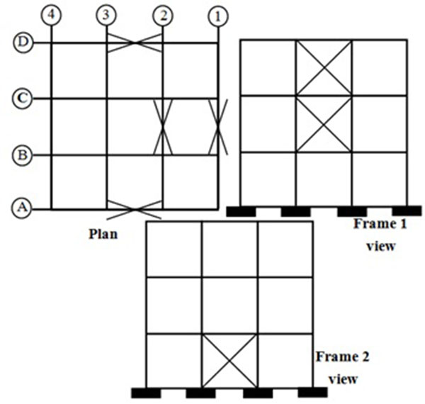
To achieve the aim of this study, two symmetric plan 3 and 6-story CBFs were designed with two different configurations (i.e. regular and irregular). All story heights and span lengths were 3 and 4 m, respectively, and braced spans were located around the perimeter of the buildings. However, on the first story for the irregular ones as shown in Fig. (1), the braced panel along the framing axis-1 was shifted to the parallel adjacent framing axis-2 to generate the corresponding CBFs with out of plane offset irregularity. The frames were assumed to be located in Los Angeles (Seismic Design Category D) with site design spectral accelerations at 0.2 and 1.0 sec of SDS=1.11 and SD1=0.61, respectively. The frames designed according to the Codes ASCE 7-10 [1], the AISC 360-10 [17] and the AISC 341-10 [18] Seismic Provisions. European IPE, IPB and tubular steel profiles were used for beams, columns and braces, respectively. In the stress–strain curve, a typical value for the modulus of elasticity (E=204000 MPa) is considered. Nominal yield stress (Fy) and ultimate stress (Fu) values of steel S235 are specified as of 235 and 360 MPa, respectively. All of the frames were designed using the ELF analysis procedure and the AISC 341-10 [18]. Because, according to Table 12.6-1 of ASCE 7-10 [1], the ELF analysis procedure is permitted for such irregular frames not exceeding 160 ft in height. It should be noted that, the columns supporting the discontinuous bracing span in axis-1 on the first story (i.e. columns 1B and 1C) were checked for the amplified seismic load combinations considering overstrength factor (Ω0) of 2.0 as per ASCE 7-10 [1] and the Seismic Provisions. According to the ASCE 7-10 [1], the response modification factor of 3.25 was assumed for the design of considered CBFs. Member sizes for all frames and other related information can be found in Akefi [19].
3. MODELING AND NON-LINEAR DYNAMIC ANALYSIS OF FRAMES
In order to investigate the non-linear behavior of the abovementioned frames and estimate their seismic parameters, all frames were modeled as three-dimensional systems using the nonlinear dynamic analysis program Seismo Struct [16]. Important aspects of the modeling technique are as follows:
3.1. Equivalent Gravity Column
The overstrength factor for each column adjacent to a braced span is computed as the ratio of average of the maximum axial load demands of the column under each of the earthquake records (Pu) to the corresponding axial load demand under the equivalent lateral force (Pe). Therefore, it is essential to calculate axial load demands of columns purely due to earthquake loading. In other words, during dynamic analysis of the models, the contribution of gravity loads in columns axial load must be excluded. To this end, the technique of equivalent gravity column (or P-Delta column) is adopted as commonly used in the literature (Sabelli et al. [20]; MacRae et al. [21]; Uriz and Mahin [22]; Hsiao et al. [23]). In this study using this technique, gravity loads of each story is located on the four corner columns as four concentrated equal masses. In other words, the corner columns are considered as the equivalent gravity columns which each of them carries the gravity loads of its own and one of the interior gravity columns excluded in the 3D model for dynamic analysis. This technique enables us to record the axial load of columns adjacent to the braced spans purely due to earthquake loading.
3.2. Members Modeling
The beam and column members are modeled with elastic beam-column elements with relevant section properties and an elastic material constitutive model. However, the brace members modeled as non-linear force-based, fiber-section, beam-column elements (i.e. distributed-plasticity based elements) with 5 integration points along their length and subdivided across their section into 150 fiber elements. For brace steel material, a Menegotto–Pinto uniaxial steel material model [16] is assumed. In order to simulate geometric imperfections and accurate modeling of in plane and out of plane global brace buckling, a physical theory model (PTM) is utilized in which an out of plane camber (geometric imperfection) is applied to the longitudinal profile of the brace members as per Uriz and Mahin [22]. The effectiveness of this macro-modeling technique to evaluate seismic response of CBFs, has been investigated and verified previously by Salmanpour and Arbabi [24], Mohebkhah and Nasrollah-Beigi [15] and D’Aniello et al. [25, 26]. D’Aniello et al. [25] conducted a comprehensive numerical study to investigate the influence of the imperfection magnitude in PTM of bracing elements in CBFs. They found that, the camber magnitude affects the drift demand, the collapse mechanism and has a noticeably impact on the seismic response parameters of CBFs at collapse. In this study, the initial geometric imperfection (displacement) of the brace interior nodes was considered equal to 0.1% of brace unbraced length as suggested by Uriz and Mahin [22]. This macro-modeling technique makes it possible to capture approximately the real behavior of CBFs with compact sections and obtain some information on their buckling strength, post-buckling behavior, out of plane deformations and hysteretic behavior. However, it is important to note that this modeling approach does not take into account plastic local buckling and low-cycle fatigue effects [25]. It should be pointed out that, in this study the gusset plate connections were not modeled. However, the beam-column connections were modeled as rigid connections where a gusset plate was present and brace to beam-column connections modeled as pinned.
3.3. Earthquake Records Selection and Scaling
To perform nonlinear dynamic analyses on the CBFs models, some earthquake records compatible with the frames site and the Code design spectrum have to be selected. According to ASCE 7-10 [1], three parameters of magnitude, fault distance and site class (i.e. soil type) are very important in records selection. This is because, most of the other parameters such as frequency content, amplitude, spectral shape and duration of the records depend on these three parameters. In this study, first 62 records selected from PEER NGA Database [27] considering the following conditions:
- Moment magnitude: 6-8.5
- Epicentral distance: 10-70 km
- Mean shear wave velocity: 175-375 m/s (corresponding to soil class D in ASCE 7-10 [1])
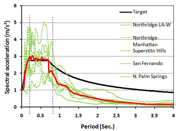
Among these earthquake records, 7 records were selected using the Harmony Search algorithm [28] and scaled using the Particle Swarm algorithm [29] to match the records average response spectrum with the target code spectrum. The main reason for choosing these algorithms in a combined strategy is that according to the previous studies in the literature [30], the Harmony Search algorithm and the Particle Swarm Optimizer algorithm present more better results for discrete data (e.g. records numbers) and continuous data (e.g. scaling factors), respectively. The selected 7 earthquake records and the corresponding scale factors for 3-story CBFs as per ASCE 7-10 [1] requirements have been shown in Table 1 with their maximum spectral matching error of 4.34%. As can be seen in Fig. (2), the mean response spectrum of the selected records represents a good match with the target code response spectrum between the code specified range of period (i.e. between periods of 0.2T and 1.5T as shown with vertical dash lines in the figure). In order to apply damping to the physical frame models, mass proportional Rayleigh damping was utilized.
| No. | Earthquake Name | Station | PGA (m/s2) | Scale Factor |
|---|---|---|---|---|
| 1 | Cape Mendocino 1992 | Rio Dell Overpass | 0.385 | 1.604 |
| 2 | Loma Prieta 1989 | Halls Valle | 0.134 | 1.415 |
| 3 | N. Palm Springs 1986 | Indio - Coachella Canal | 0.053 | 1.251 |
| 4 | Northridge 1994 | Manhattan Beach | 0.201 | 2.316 |
| 5 | Northridge 1994 | LA - W 15th St | 0.104 | 1.114 |
| 6 | San Fernando 1971 | 125 Lake Hughes | 0.145 | 0.772 |
| 7 | Superstitn Hills(B) 1987 | Centro Imp. Co. Cent | 0.358 | 1.776 |
| Error (%) | 4.34 | |||
4. RESULTS AND DISCUSSION
In this section, all of the regular and irregular CBFs are subjected to nonlinear dynamic analysis using the scaled earthquake records presented in the previous section. For each frame, three seismic parameters (frame overall overstrength factor, column overstrength factor and inelastic dynamic inter-story drift demands) are estimated and then they are compared to the corresponding values given in ASCE 7-10 [1] for the ELF analysis of CBFs.
4.1. Three-story CBFs
4.1.1. Overstrength Factors
Overstrength factor is an important parameter in seismic design of structures based on the equivalent linear analysis procedure capacity design concept. For each frame, the frame overall overstrength factor is calculated by dividing the ultimate dynamic base shear demand (Vu) by the elastic base shear demand (Ve) as per the equivalent static lateral force procedure. This factor was determined as 2.74 and 2.21 for the studied regular and irregular 3-story CBFs, respectively.
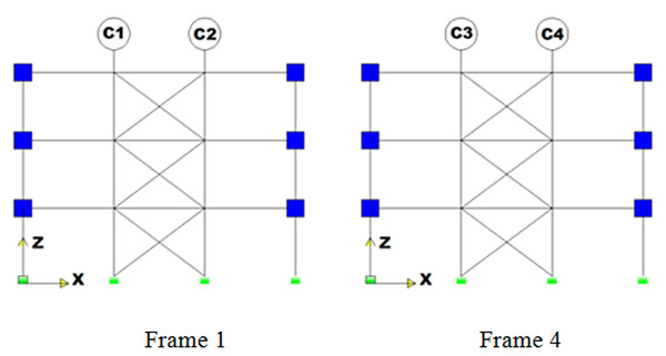
In order to estimate the axial load demand of each column adjacent to the braced spans, the ratio of the average maximum axial load demands of the column under each of the earthquake records (Pu) to the corresponding axial load demand under the equivalent lateral force (Pe) is computed. To have a clear understanding of the height-wise variation of columns axial demands, the columns adjacent to the braced spans in the regular and irregular 3-story CBFs are distinguished with a symbol as shown in Figs. (3 and 4), respectively. The normalized column demands (overstrength factors) variations for the regular and irregular 3-story SCBFs are presented in Tables 2 and 3, respectively. It can be seen that, the abovementioned overall overstrength factors are not equal to the columns axial demands given in Tables 2 and 3.

| Column | Story | Pe (kN) | Pu (kN) | Ω |
|---|---|---|---|---|
| C1 | 1 | 1100.5 | 2651.9 | 2.41 |
| 2 | 565.9 | 1382.7 | 2.44 | |
| 3 | 157.2 | 387.0 | 2.46 | |
| C2 | 1 | 1100.5 | 2588.8 | 2.35 |
| 2 | 565.9 | 1380.1 | 2.44 | |
| 3 | 157.2 | 376.4 | 2.39 | |
| C3 | 1 | 1133.4 | 2643.4 | 2.33 |
| 2 | 578.6 | 1375.9 | 2.38 | |
| 3 | 152.4 | 381.03 | 2.50 | |
| C4 | 1 | 1133.4 | 2562.2 | 2.26 |
| 2 | 578.6 | 1356.2 | 2.34 | |
| 3 | 152.4 | 390.1 | 2.56 |
| Column | Story | Pe (KN) | Pu (KN) | Ω |
|---|---|---|---|---|
| C1 | 1 | 825.6 | 1571.7 | 1.90 |
| 2 | 571.4 | 1097.5 | 1.92 | |
| 3 | 158.6 | 309.1 | 1.95 | |
| C2 | 1 | 825.6 | 1584.2 | 1.92 |
| 2 | 571.4 | 1125.6 | 1.97 | |
| 3 | 158.6 | 299 | 1.89 | |
| C3 | 1 | 1055.3 | 2151.5 | 2.04 |
| 2 | 572.5 | 1217.4 | 2.13 | |
| 3 | 151.1 | 349.8 | 2.31 | |
| C4 | 1 | 1055.3 | 2126.3 | 2.01 |
| 2 | 572.5 | 1208.3 | 2.11 | |
| 3 | 151.1 | 381.6 | 2.53 | |
| C5 | 1 | 359.5 | 770.7 | 2.14 |
| C6 | 1 | 359.5 | 767.4 | 2.13 |
According to ASCE 7-10, an overstrength factor of 2.0 has been proposed for seismic design of CBFs. This factor can be compared with the normalized column demands given in Table 2 (i.e. between 2.26 and 2.56 with an average of 2.41) for the regular CBF. Therefore, it can be concluded that the use of code-prescibed overstrength factor of 2.0 to amplify the elastic column axial demands of the regular CBF in the ELF analysis procedure is unconservative.
Considering the normalized column demands given in Table 3 for columns C1 and C2 in Frame-1 (i.e. between 1.89 and 1.97 with an average of 1.92), however, it can be seen that the use of overstrength factor of 2.0 to amplify the elastic axial demands of these columns (even for the columns supporting the discontinuous bracing span) in the irregular CBF is on the safe side. However, it seems that an overstrength factor of about 2.5 is more conservative to be used for the columns adjacent to the shifted bracing span (i.e. columns C5 and C6) and columns C3 and C4 in Frame-4.
4.1.2. Inelastic Inter-story Drift Demands
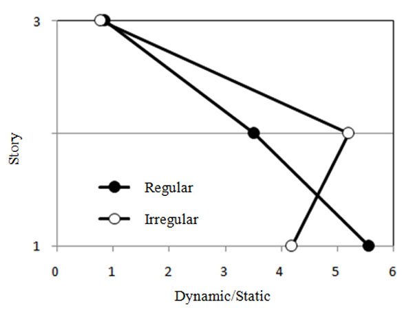
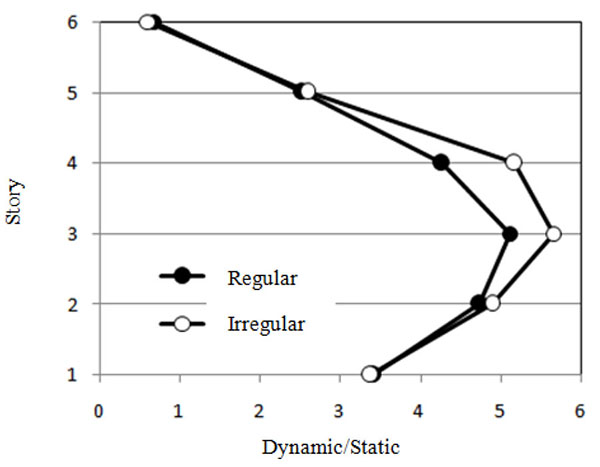
According to the UBC-97 [31] in design of a system using the ELF analysis procedure, the inelastic drift demand of the system is estimated by multiplying the elastic drift demand by a deflection amplification factor of 0.7R. In order to investigate the accuracy of this method to estimate the inelastic drift demands of the studied CBFs, variations of the ratio of the inelastic dynamic drift demands to the UBC estimated drift demands are plotted in Fig. (5) for comparison. Inelastic story drifts were computed from the dynamic analyses as the average of the maximum story drifts for each story from seven analyses. As it can be seen, the UBC estimation of the top story drifts for both regular and irregular CBFs is acceptable. However, the inelastic dynamic drifts are more than five times higher than the Code estimation for lower stories in the studied CBFs. Furthermore, it can be observed that the inelastic dynamic amplification is not uniform for the lower stories.
According to the deformed geometry of the CBFs in Fig. (6), it is seen that all bracing members aligned parallel to the applied earthquake direction have been yielded or buckled dissipating the earthquake input energy (yielding of the bracing members in this figure has been highlighted in red color). However, the bracing members aligned perpendicular to the applied earthquake direction in the irregular frame, have not been yielded or buckled. This result indicates that the imposed irregularity in this 3-story frame has not been so severe to induce additional torsional torques and hence to make the orthogonal bracing members to participate in resisting the torque.
4.2. Six-story CBFs
4.2.1. Overstrength Factors
Similar to the previous section, the overall overstrength factors were calculated for the 6-story frames. This factor was determined as 2.73 and 2.66 for the studied regular and irregular 6-story CBFs, respectively. Comparing the obtained normalized column demands for the regular 6-story CBF (i.e. between 1.98 and 2.35 with an average of 2.13) to the Code overstremgth factor (2.0) indicates that that the use of ASCE 7-10 overstrength factor to amplify the elastic column axial demands of the frame in the ELF analysis procedure is unconservative, too.
Furthermore, considering the obtained normalized column demands for the irregular 6-story CBF (i.e. between 1.94 and 2.29 with an average of 2.08), it can be concluded that the use of overstrength factor of 2.0 to amplify the elastic axial demands of these columns (even for the columns supporting the discontinuous bracing span) in the irregular CBF is approximately acceptable. However, it is seen that an overstrength factor of about 2.6 is more conservative to be used for columns adjacent to the shifted bracing span (i.e. columns C5 and C6).

4.2.2. Inelastic Inter-story Drift Demands
Again, similar to the 3-story frames in the above, variations of the ratio of the inelastic dynamic drift demands to the UBC estimated drift demands of the 6-story CBFs are plotted in Fig. (7) for comparison. As it can be seen, the UBC estimation of the top story drifts for both regular and irregular CBFs is acceptable. However, the inelastic dynamic drifts are more than four times higher than the Code estimation for intermediate stories in the studied regular CBF (and more than 5 times in the irregular one). Furthermore, it can be observed that again the inelastic dynamic amplification is not uniform for the lower stories of these frames, too.
CONCLUSION
In this paper, a three-dimensional finite element macro-model developed for the nonlinear dynamic analysis of two 3 and 6-story CBFs with and without out of plane offset irregularity. The model has the ability to consider both geometric and material nonlinearities. However, the story diaphragms were assumed to be rigid. The main conclusions from the study are as follows:
- The use of code-prescibed overstrength factor of 2.0 to amplify the elastic column axial demands of the regular 3 and 6-story CBFs in the ELF analysis procedure is unconservative.
- The use of code-prescibed overstrength factor of 2.0 to amplify the elastic axial demands of the columns adjacent to the main discontinuous bracing span (even for the columns supporting the upper bracing panels) in the irregular 3-story CBF is on the safe side. However, it is not conservative to be used for the columns adjacent to the shifted bracing span and the continuous bracing span columns located on the other side of the frame.
- The use of code-prescibed specified overstrength factor of 2.0 to amplify the elastic axial demands of the columns adjacent to the main discontinuous bracing span (even for the columns supporting the upper bracing panels) in the irregular 6-story CBF as well as the opposite continuous bracing span columns is on the safe side. However, it is not conservative to be used for the columns adjacent to the shifted bracing span.
- Although, the UBC estimation of drifts (i.e. amplified elastic drifts) gives acceptable results for the top story of both regular and irregular CBFs, however, underestimates the inelastic dynamic drifts of lower stories in the studied CBFs.
As the final conclusion, it appears that the out-of-plane irregularity known as the horizontal irregularity in current seismic codes, does not necessarily lead to a poor seismic behavior of the studied CBFs with the assumed irregularity. However, it performs poor in terms of inter-storey drifts and story rotations compared to the regular one. It should be noted that, owing to the limited number of structures irregularity cases studied in this study as well as the assumption of rigid story diaphragms, these findings are not yet conclusive and further studies must be carried out to validate the results for more general cases.
CONFLICT OF INTEREST
The authors confirm that this article content has no conflict of interest.
ACKNOWLEDGEMENTS
Declared none.


