All published articles of this journal are available on ScienceDirect.
On the European Norms of Design of Buckling Restrained Braced Frames
Abstract
The application of buckling restrained braced frames is hindered in Europe by the absence of a standardized design procedure in Eurocode 8, the European seismic design standard. The presented research aims to develop a robust design procedure for buckling restrained braced frames. A design procedure is proposed by the authors. Its performance has been evaluated for buckling restrained braced frames with two-bay X-brace type brace configurations using a state-of-the-art methodology based on the recommendations in the FEMA P695 document. A special numerical material model was developed within the scope of this research to represent the behavior of buckling restrained braces more appropriately in a numerical environment. A total of 24 archetype designs were prepared and their nonlinear dynamic response was calculated using real ground motion records in incremental dynamic analyses. Evaluation of archetype collapse probabilities confirms that the proposed design procedure can utilize the advantageous behavior of buckling restrained braces. Resulting reliability indices suggest a need for additional regulations in the Eurocodes that introduce reasonable structural reliability index limits for seismic design.
1. INTRODUCTION
A design procedure shall be an effective methodology that can be applied by practicing engineers to calculate the geometric and material properties of structural members and ensure the advantageous behavior of the resulting structural system. It is typically a set of rules and limits prescribed in the applicable standard. In order to provide guidance for a wide range of design cases, the specifications are composed of a series of conditional tasks and relatively simple formulae that often provide conservative approximations to complex phenomena. This is especially true for the design of nonlinear dissipative anti-seismic structural solutions.
Evaluation of such a procedure is a difficult task, because of the vast number of possible scenarios required to take the variability of the structural behavior and the seismic hazard into account. Extensive generalization and extrapolation from small samples is not recommended, because of the often nonlinear relationship between realistic structural behavior and design variables. The large number of design variables and the nonlinearity of the problem make seismic design especially difficult to evaluate with sufficient accuracy.
The Buckling Restrained Brace (BRB) is characterized by complex nonlinear cyclic hardening behavior. This stems from its special configuration (Fig. 1). A conventional BRB is a steel core surrounded by a concrete hollow casing that provides continuous lateral support to it. Because the continuous lateral support restrains flexural buckling of the core, the cross-section of the steel core can be reduced significantly. The hollow casing and the steel core are decoupled by so-called unbonding material [1] or by leaving an air gap between them [2]. This measure ensures stable cyclic behavior by preventing the contribution of the casing to axial load resistance.
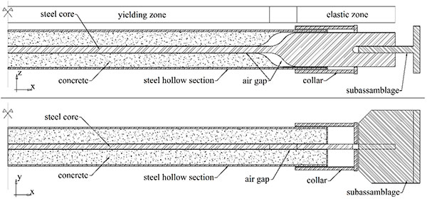
BRB element behavior has been extensively studied through experimental tests in North America (e.g. [1-4]), in Asia [5-7] and recently also in Europe (e.g. [8-10]). The large number of test results available facilitates verification of even complex numerical models and enables researchers to develop sophisticated representations of BRB behavior. However, until recent years, the lack of computational resources impeded application of complex nonlinear behavior and direct consideration of demand and capacity variability. Therefore, several research efforts – including studies on Buckling Restrained Braced Frame (BRBF) design – from the past decade used only a small set of scenarios or involved other simplifications for feasibility. Bosco and Marino suggested a design procedure with a behavior factor between 2.5 and 4.7 depending on the design story drift angle. They evaluated the procedure through the performance of three archetype structures at two levels of seismic intensity [11, 12]. Asgarian and Shokrgozar on the other hand performs advanced nonlinear analysis on a large set of structures, but their excessively simplified numerical frame models might lead to significant errors in structural response [13]. Similar simplified approaches are presented in several further examples from the literature [14-16].
The authors believe that economy and assurance of sufficiently low failure probability with high confidence shall be the primary targets of a good design procedure. Therefore, its merits can only be judged by robust and reliable evaluation of collapse probability. This requires a framework for probabilistic assessment of the performance of a large number of typical structural solutions under the various seismic hazard scenarios. Such an assessment became feasible due to the rapid improvement in computer performance.
The foundation of probabilistic structural performance analysis is performance-based earthquake engineering (PBEE) that became an element of standards in the United States in the late 1990s [17, 18]. In PBEE the realistic nonlinear response of the structure is analyzed at several ground motion intensity levels. A specific design option is judged by comparing the expected losses during the lifetime of the structure to the cost of the given design. The so-called first generation PBEE procedures had limited consideration of the inherent uncertainty in the input data and numerical models [19]. Considered uncertainty was typically limited to the probabilistic definition of the seismic hazard.
The Pacific Earthquake Engineering Research Center (PEER) proposed an advanced performance assessment framework in the early 2000s [20]. The framework is based on four separate processes that provide an explicit and transparent approach to PBEE. The first step is seismic hazard analysis, where the hazard at a given site is described by an intensity measure (IM). The second step is structural analysis; the evaluation of engineering demand parameters (EDPs) such as maximum interstory drift or component forces based on the IM that describes the hazard. Damage (DM) is expressed as a function of EDPs in the third step, while the final phase calculates the decision variables (DV) such as expected loss and risk from the experienced damage.
In the early 2000’s a group of experts developed a procedure for the quantification of seismic performance factors of structures using the above framework for PBEE [21]. The procedure describes structural performance through nonlinear collapse simulation on finite element models of archetype structures. The archetypes shall be designed with the procedure under evaluation and their set shall capture the variability of the performance characteristics of the structural system under consideration. The procedure is typically cited as the FEMA P695 methodology in literature. It is the basis of the methodology applied in this research.
2. MATERIALS AND METHODOLOGY
2.1. Probabilistic Approach to Seismic Performance Evaluation
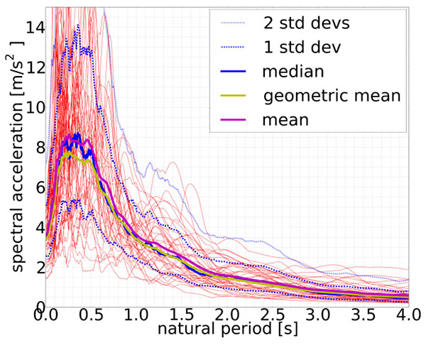
The seismic demand is described by a set of 22 pairs of pre-defined ground motion records that were selected from the PEER Next-Generation Attenuation (NGA) database [22] to give a good approximation of the aleatoric uncertainty in the earthquake hazard. A plot of the 5% damped response spectra and their geometric mean, arithmetic mean, median and standard deviation are shown in Fig. (2).
Engineering demand parameters are evaluated by calculating structural response through nonlinear response history analysis with each of the 44 ground motion records scaled to several intensity levels. This evaluation procedure is based on the concept of Incremental Dynamic Analysis (IDA) [23]. Performance of frame structures is typically described by the maximum interstory drift ratio (EDP) as a function of spectral acceleration at the dominant structural period (IM). Fig. (3) displays a typical IDA response of a BRBF to illustrate this procedure. Each continuous line represents the EDP under the effect of one ground motion record at several IM levels. The red line on the figure is defined by connecting the median EDPs at each IM level. The run of the curves resembles that of the capacity curves from pushover analysis. Some researchers consider IDA curves the capacity curves of dynamic analysis, because similarly to pushover curves, they provide ample information on the nonlinear response of structures under a large range of seismic intensities. Note how the initial elastic behavior is followed by a reduction in stiffness (hence the smaller slope), period elongation and eventually structural failure because of sidesway collapse for the example in Fig. (3). Also note how the scatter of IDA curves describes the inherent uncertainty in the seismic hazard and encourages a probabilistic approach to damage assessment.
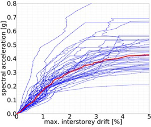
Depending on the design procedure and the requirements of corresponding standards, several DM levels can be evaluated. Researchers are primarily interested in collapse. The methodology recognizes that every structural system has several possible modes of failure. When the given failure mode can be properly modeled in finite element code, it is considered in the analysis and will be apparent in EDPs. An example of such an even is soft story formation in braced frames that results in large interstory drift values at the given story. This type of failure can be registered in a straightforward manner if the maximum interstory drift is selected as an EDP (Fig. 3). When it is not possible or more often not feasible to simulate a failure mode directly, its influence can be taken into account in a post-processing step. This so-called non-simulated collapse mode typically introduces limit state checks on structural response quantities. An example of such events is fracture in the hinge regions of steel frames that can be controlled by limiting the plastic rotation of the hinges.
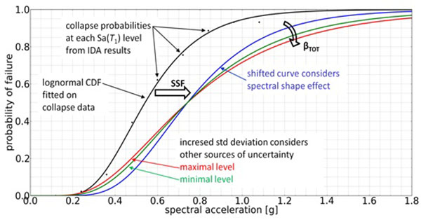
In the evaluation phase, collapse intensity (i.e. the spectral acceleration intensity at the dominant period of the structure that initiates global failure) is considered a random variable with lognormal distribution and it is described by a fragility curve Fig. (6). The curve is defined by the median collapse capacity (i.e. the IM level where half of the ground motion records lead to collapse) of the corresponding structure. The decision variable in FEMA P695 is the probability of structural collapse at the maximum considered earthquake (MCE) intensity. The MCE intensity is 150% of the design seismic intensity level. Therefore, reliable estimation of the fragility curve is of high importance. There are a number of different methods available to define fragility curves from IDA results. This research applies a so-called direct approach. It uses the collapse Sa(T1) (i.e. spectral acceleration at the dominant period of vibration) values for each ground motion record from IDA results as samples of a lognormal distribution and finds the best fitting mean and variance. The sought fragility curve is the cumulative density function of this distribution.
Record-to-record uncertainty (βRTR) is included in the analysis and it is responsible for the variance in EDPs at a given IM level. The procedure recommended in FEMA P695 modifies the standard deviation of collapse intensity to explicitly consider three additional sources of uncertainty:
- Design requirements uncertainty (βDR) is influenced by the robustness and completeness of the design specifications, with special focus on the probability of occurrence of unanticipated failure modes.
- Test data uncertainty (βTD) describes the quality of test data with emphasis on the ability to predict nonlinear response (including failure) when the structure is subjected to large seismic demands. It is also important to collect sufficient data for the proposal of design criteria that can ensure the reliable performance of the designed system.
- Modeling uncertainty (βMDL) depends on how well the archetypes represent the structural system and the ability of structural models to capture the collapse behavior of the structures.
The resulting total standard deviation that shall be applied at the random collapse capacity variable:
 |
(1) |
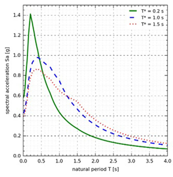
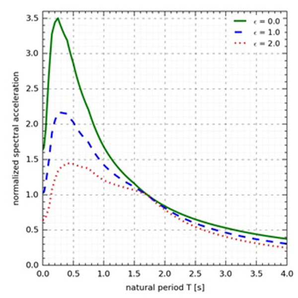
Besides uncertainty, the influence of the so-called spectral shape effect also requires modification of the fragility curves. Several researchers have drawn attention in the past decade to the observation that the spectrum of an earthquake with high spectral intensity at a given frequency can be very different from another with lower intensity at the same frequency [24-27]. The variable epsilon (measured in units of standard deviation) is used to express the difference between the spectrum of interest and the median spectrum from the same seismic source. A spectrum with a positive ε(T) has a peak in the vicinity of the T period as shown in Fig. (4). As a consequence of this difference in spectral shape, when a positive and a zero ε spectrum are scaled to the same Sa(T) spectral acceleration, the positive epsilon spectrum is expected to be below the zero epsilon spectrum for the majority of periods other than T (Fig. 5). Therefore, response of structures with higher modes of vibration as well as those characterized by period elongation will be overestimated. The former group is highly influenced by the short period range, while the latter is more sensitive to the higher period range. The important implication of this effect is that the collapse intensity of a structure under high intensity seismic excitation will be underestimated unless it is assessed by ground motion records with appropriate ε values at the dominant period of the structure [28, 29].
The FEMA P695 framework uses an approximately epsilon-neutral record set and the effect of spectral shape is considered in a post-processing step by increasing the median collapse capacity with the so-called spectral shape factor (SSF). The SSF is the result of detailed analysis on a large number of reinforced concrete frames and wooden structures in a Californian setting [30]. Its value is based on the ductility and the dominant period of the structure and it also accounts for the influence of seismic intensity on the spectral shape. Because the SSF can be as high as 1.61, its application can lead to fundamental changes in analysis results (Fig. 6).
The raw fragility curves from IDA need to be modified to take the aforementioned additional sources of uncertainty and the spectral shape effect into account. Fig. (6) explains the steps of modification. The spectral shape factor is used to increase the median collapse capacity and practically shift the fragility curve along the horizontal axis. The combination of four uncertainty sources is presented in Eq. (1). Record-to-record uncertainty is the standard deviation of the fragility curve from IDA. The level of uncertainty from each source is defined based on qualitative judgment from recommendations in three tables in FEMA P695. Because the uncertainty assigned to the external sources has significant influence on collapse probability, a range of values is assigned that represent the best and worst conceivable cases. A lower and higher bound of total uncertainty is calculated from the above values and resulting green min and red max fragility curves are shown in Fig. (6).
FEMA P695 uses pre-defined limits on collapse probability at the MCE intensity level to evaluate the performance of a particular design procedure. The average collapse probability shall be below 10%. Outliers are also limited, because no building can have higher than 20% probability of collapse from an MCE event. Although adjustment of these limits to the local requirements is possible and recommended by the authors of FEMA P695, the authors are concerned about the approach on a conceptual level. It successfully describes the probability of collapse under seismic events that generate spectral accelerations equal to 150% of the design Sa(T1), but it does not rate the performance of the structure at other intensities.
The basis of safety in the Eurocodes is reliability, namely the probability of failure over the lifetime of the structure. This approach is also suggested by researchers in the US as a more accurate alternative [31]. Therefore, in order to be consistent with European regulations, the collapse probability evaluation needs to be enhanced in the applied methodology. Annex B and C of Eurocode 0 [32] prescribe a general limit of 10-4 probability of failure over 50 years for buildings under ultimate limit state effect. Although recent research suggests that this value is overly conservative for seismic design, there is no consensus on the appropriate value for this measure [8, 33-35]. The standard already recognizes and uses different values for the evaluation of fatigue effects for instance, thus it is conceptually possible to introduce custom values for seismic effects as well. This research verifies BRBF performance using the recommendations from FEMA P695, but the reliability indices are also calculated and their application possibilities are discussed.
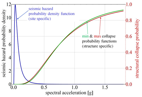
The evaluation of collapse probability over a given time period requires a characteristic hazard curve that describes a relationship between Sa(T1) and the probability of occurrence of ground motions at the site. Such curves are provided by the U.S. Geological Survey [36] and the European Facility for Earthquake Hazard and Risk (EFEHR) [37] for the United States and Europe, respectively. The European source is used to select hazard curves for this research.
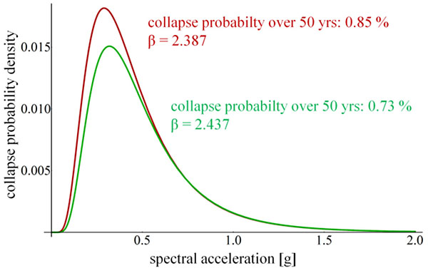
Fig. (7) displays the seismic hazard probability density function (PDF) based on the assumption of lognormal data distribution as well as the cumulative distribution function (CDF) of the conditional collapse probability of the structure. The probability of structural failure from seismic events at different intensities over the selected timeframe can be expressed as the product of the hazard PDF and the collapse CDF of a structure. The resulting PDF-like curve on Fig. (8) clearly shows the most perilous range of spectral intensities for the structure and site under consideration.
The two results represent the lower and upper bound scenarios using the fragility curves from Fig. (6). The total probability of collapse is calculated by numerically integrating each curve over the entire spectral acceleration domain. Integration yields 0.0073 – 0.0085 probabilities for the two limiting cases. This expresses that the probability of structural collapse from earthquakes in the next 50 years is 0.73% - 0.85%. The β reliability index in the Eurocode Standards expresses the distance of the probability of failure on the quantile function from the mean of the standard normal distribution in units of variance. That structure at the given site is characterized by β in the range of 2.387 – 2.437. Although the structure fulfils the requirements of FEMA P695, note that the β values are significantly lower than the generally recommended β=3.8 in Eurocode 0 (EC0) [32]. The applicability of current EC0 limits for seismic reliability assessment is discussed in the results section of this paper.
2.2. Investigated Scenarios and Structural Archetypes
The scope of this research is limited by the following assumptions:
- BRBF are designed with a two-bay X-brace type of concentrically braced frame topology (Fig. 9) for an example of this topology).
- BRB elements are considered pinned in the numerical models. The actual rigidity of the connection may result in considerable secondary stresses because of frame deformations. This effect is indirectly considered in the models: specimens are experimented with their actual bolted or welded connections and the effect of rotation on brace behavior is considered in the experimental setup and thus incorporated in the hysteretic response of the braces to which the numerical models are calibrated.
- BRB element design (normally completed by the manufacturer) assures that BRBs have sufficient resistance against local failure in their connections and local flexural buckling of their steel core outside of its yielding zone.
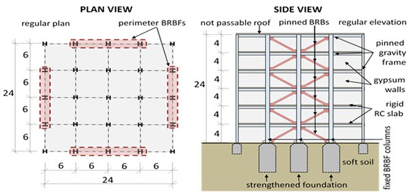
The design procedure presented in Section 2.3 is evaluated using typical representations of BRBF, the so-called structural archetypes. Archetypes are organized into Performance Groups that represent specific design scenarios and collect buildings that were designed using similar objectives and boundary conditions. The Performance Groups and their characteristics are summarized in Table 1.
| Group No. | Characteristics | Number of Archetypes | ||
|---|---|---|---|---|
| Design Load Level | Period Domain | |||
| Gravity | Seismic | |||
| PG-1 | Low | Low | Short | 3 |
| PG-2 | Long | 3 | ||
| PG-3 | High | Short | 3 | |
| PG-4 | Long | 3 | ||
| PG-5 | High | Low | Short | 3 |
| PG-6 | Long | 3 | ||
| PG-7 | High | Short | 3 | |
| PG-8 | Long | 3 | ||
The design gravity load level represents two extreme combinations of braced floor area and distributed dead load for the BRBF system. Because frames are expected to perform better under less gravity loading, those verifications are concerned about the feasibility of this system for such cases, especially in regions of low seismicity. High gravity loads are of particular interest because of their influence on second order effects, such as the global overturning moment. Furthermore, the mass of the building directly affects the period of its vibration and the base shear force under seismic excitation. Regions of moderate and very high seismicity are considered as the two seismic hazard cases to verify the applicability of the proposed procedure on both ends of the seismic intensity spectrum.
Archetypes were divided into two sets for each load condition. The short period domain set contains stiffer structures with dominant periods typically below Tc of the corresponding design spectrum. Design of these structures is typically force controlled and their performance is limited by the load bearing capacity of their members. The other group contains archetypes with longer natural periods. These structures are more affected by displacement limits and second order effects. Each group contains three archetypes, thus the design and analysis of 24 archetypes is required for the presented evaluation.
Each archetype is a steel frame structure with two-bay X-brace type BRBF configuration installed at its perimeter frames for lateral load resistance (Fig. 9). BRBF columns have rigid supports. The plan of the buildings is either a 4x4 or a 6x6 grid and they are regular in elevation. Note that structures occupying a larger area are also covered by these archetypes, because in such cases more than two bays are typically braced. The presented cases identify a minimum and maximum braced floor area that can be efficiently supported by a two-bay X-brace pinned BRBF configuration. Floors are made of reinforced concrete slabs; the walls are made of gypsum boards. The site is located on soft soil (vs,30 < 180 m/s) in a zone of either moderate- (Hungary – PGA = 0.15 g) or high seismicity (Albania – PGA = 0.4 g). Hazard curves from both sites are used during evaluation to assess a reliability index for each archetype. Detailed parameters of each archetype are presented in Table 2.
The structures are designed using linear modal response spectrum analysis. The objective was to mimic the tools and expertise of practicing engineers and evaluate the expected performance of their designs. An algorithm was developed by Tamás Balogh that performs the design of BRBF automatically. It uses heuristic search to find an optimal solution in the parameter space of design variables. It performs the design checks prescribed in section 2.3 and searches for column and BRB sections that fulfill all required conditions. Columns are selected from standard HE A, HE B and HE M sections. BRB cross-section sizes are selected from an array of candidates in the range of 500 mm2 to 10,000 mm2 with a step size of 10 mm2. Note that the heuristic search algorithm is not limited to pinned BRBF, it can be used for a wide range of structures. While pinned BRBF could be designed by hand in a limited number of iterations, design of dual systems of BRBs and moment frames poses a significantly greater challenge to engineers. The developed algorithm is especially useful for such applications where multiple local optima are available. More details on the algorithm are explained in [38-40].
2.3. Design Procedure for BRBF
Although design of buckling restrained braced frames is studied in the literature [11, 13-16], no comprehensive design procedure has been proposed and validated for European application. The only European study on the topic [11] proposes a procedure with significant approximations in both design and validation. Furthermore, the proposed procedure does not fit easily in the current design concept of Eurocode 8. Several studies are interested only in the evaluation of the optimal behavior factor (q) that shall be applied for this system [12-14].
Their recommendations show significant variation which is explained by the simplicity of their approach to numerical simulation. BRB behavior is typically represented by a bilinear material model with significant kinematic hardening [16]. The hardening rate ranges from 2% to 5% of the initial stiffness. This leads to significant overestimation of BRB stiffness and capacity and generates errors that are typically not on the conservative side. Columns are often modeled as truss members on all levels with pinned connections, thus the effect on bending moments is excluded from the analysis [13]. Real BRBF applications often need fixed and continuous columns for the braced frame in order to limit the horizontal deformations of the structure under earthquakes. As it is demonstrated by the results in this paper, these columns are susceptible to failure at high levels of seismic intensity because of bending. Buckling on the other hand, that is considered in Asgarian and Shokrgozar [13] by applying initial imperfection on their models, is not expected to occur once the columns are properly considered as continuous members.
| PG | ID | Stories | Bay Geometry | Floor Plan | Seismicity | |||
|---|---|---|---|---|---|---|---|---|
| Location | PGA | Soil Type | T1 [s] | |||||
| PG - 1 | 11 | 2 | 4.0 m x 6.00 m | 4 x 4 grid | HUN | 0.15 | D | 0.81 |
| 12 | 3 | 3.5 m x 5.25 m | 0.96 | |||||
| 13 | 3 | 4.0 m x 6.00 m | 1.04 | |||||
| PG - 2 | 14 | 4 | 4.0 m x 6.00 m | 1.24 | ||||
| 15 | 5 | 4.0 m x 6.00 m | 1.44 | |||||
| 16 | 6 | 4.0 m x 6.00 m | 1.63 | |||||
| PG - 3 | 21 | 2 | 4.0 m x 6.00 m | ALB | 0.4 | 0.53 | ||
| 22 | 3 | 3.5 m x 5.25 m | 0.60 | |||||
| 23 | 3 | 4.0 m x 6.00 m | 0.65 | |||||
| PG - 4 | 24 | 4 | 4.0 m x 6.00 m | 0.73 | ||||
| 25 | 5 | 4.0 m x 6.00 m | 0.90 | |||||
| 26 | 6 | 4.0 m x 6.00 m | 1.00 | |||||
| PG - 5 | 31 | 2 | 4.0 m x 6.00 m | 6 x 6 grid | HUN | 0.15 | 0.81 | |
| 32 | 3 | 3.5 m x 5.25 m | 0.95 | |||||
| 33 | 3 | 4.0 m x 6.00 m | 1.05 | |||||
| PG - 6 | 34 | 4 | 4.0 m x 6.00 m | 1.26 | ||||
| 35 | 5 | 4.0 m x 6.00 m | 1.46 | |||||
| 36 | 6 | 4.0 m x 6.00 m | 1.65 | |||||
| PG - 7 | 41 | 2 | 4.0 m x 6.00 m | ALB | 0.4 | 0.55 | ||
| 42 | 3 | 3.5 m x 5.25 m | 0.62 | |||||
| 43 | 3 | 4.0 m x 6.00 m | 0.66 | |||||
| PG - 8 | 44 | 4 | 4.0 m x 6.00 m | 0.73 | ||||
| 45 | 5 | 4.0 m x 6.00 m | 0.90 | |||||
| 46 | 6 | 4.0 m x 6.00 m | 1.03 | |||||
Conformance to existing Eurocode regulations was of primary interest during the development of the design procedure applied in this research. Therefore, although the specifications in AISC 341-10 [41] were considered and they are reflected in the result, their direct application was not sought. The applied procedure employs the existing capacity design rules for concentrically braced frames (CBF) in EC8 6.7 and introduces a limited number of modifications to make it appropriate for BRBF design. The introduction of BRB bracings as a third category besides diagonal and V bracings is proposed. The main advantage of this approach is its simple application in a European design environment, where practicing engineers are already familiar with EC8 and its regulations. The background and the rules of the applied BRBF design procedure are explained in detail in Vigh et al. [42], the following is a short summary of its most important considerations:
- In elastic analysis braces shall be modeled using an increased, equivalent initial stiffness value.
- Both tension and compression elements need to be modeled even in linear static analysis.
- The braces shall fulfill the requirements of the EN 15129 standard taking into account the suggested modifications in Zsarnóczay et al. [43].
- Unbalanced loads from asymmetric hardening shall be considered for columns of the braced frame that have at least two connecting braces.
- A more stringent variation limit for brace overstrength (Ω) over the height of the structure is suggested. Instead of the 25% in EC8 6.7.3 (8), the ratio of maximum and minimum Ω values shall not exceed 10%. This modification has been shown to effectively reduce the likelihood of soft story formation and considerably increase BRBF performance [44]. Unlike regular steel sections, the cross-sectional area of BRBs can be tailored to the requirements of the given design, thus this variation limit is not expected to pose a difficulty for practical design.
- The overstrength factor (γov) shall be calculated with the following expression:
where γov,m is the material overstrength; ωεd and βεd are the strain hardening adjustment factor and the compression strength adjustment factor at the design strain level, respectively. The proposed value for γov,m shall be based on material test results from materials of actual BRBs and it is a manufacturer-specific number.

(2) - A behavior factor of 7.0 is proposed for concentrically braced frames with pinned BRBs in two-bay X-brace configuration provided that the braces are proven to have sufficient ductility. (It was assumed in this research that BRBs can sustain at least 2 cycles of displacement controlled loading at 6% yielding zone strain level.) BRBs with insufficient ductility shall only be designed with a behavior factor of 6.0. This results in a stiffer structure and limited interstory drifting, thus effectively reduces the probability of BRB rupture because of low-cycle fatigue or excessive deformation.
- BRBF columns shall be made of Class 1 or 2 cross-sections to ensure that the columns have sufficient deformation capacity under cyclic loading. This measure is necessary to avoid local plate buckling in columns under high drifts at large seismic intensities.
Note that the proposed design procedure has been tested within the scope of this research. Therefore, BRBF with parameters outside of that scope (e.g. taller than 25 m, single diagonal configuration, etc. see section 4 for details) shall not be designed with this procedure unless its performance is verified by pushover and/or response history analysis.
2.4. Numerical BRBF Model
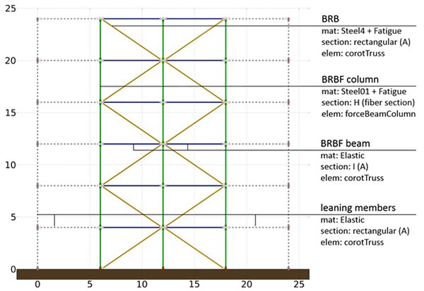
Performance assessment requires realistic simulation of nonlinear behavior; therefore, analyses are performed within an advanced finite element modeling environment. The OpenSees 2.2.2 finite element code is used for this research. Fig. (10) displays the simplified two dimensional numerical model of the BRBF that was used for the analyses.
All elements, but the braced frame columns are made of corotational trusses to properly take second order effects into account. Corotational trusses use a set of corotational axes which rotate with the element to take into account an exact geometric transformation between local and global frames of reference. Since truss members are only subjected to axial forces, the cross-sectional area of the elements is sufficient information for the analysis. Beams and the leaning truss are modeled with a perfectly elastic material and a high E0 = 10,000 GPa stiffness to mimic perfectly rigid behavior.
Braced frame columns on the other hand are continuous members with fixed supports and complex internal forces; therefore, they are modeled with the more sophisticated Force Beam Column element. This element represents the concept of distributed plasticity in OpenSees. Column cross-sections are discretized as fiber sections that approximate element response by evaluation of stresses in individual fibers. P-Delta geometric transformations are applied for proper consideration of geometric nonlinearity. Columns of the braced frame use the bilinear Steel01 material with a 0.5% hardening ratio to simulate realistic steel behavior. Deformation of columns is limited at 10% strain at the extreme fibers of the cross-sections to simulate the plastic rotation capacity limits of Class 2 sections.
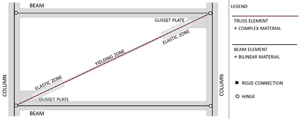
Buckling Restrained Braces are modeled as single truss finite elements coupled with a complex numerical material model. The finite element model is schematically illustrated in Fig. (11). The cross section of the truss element is that of the BRB yielding zone. The influence of the elastic zones and connections is taken into account by increasing the initial stiffness of the material through its Young’s modulus. The modified stiffness value can be calculated with the following expression:
 |
(3) |
Where Eeq,0 is the modified initial stiffness; Es is the Young’s modulus of the steel material; ltot, ly, ltr, and lel are the length of the complete element, its yielding zone, transition zones, and elastic zones, respectively; bel and by are the width of the element at the yielding and elastic zones, respectively. The ratio of Eeq,0 and Es is the so-called Stiffness Modification Factor (SMF, fSM) in BRB design practice and its value typically ranges from 1.05 to 1.50 with longer braces having smaller modification factors.
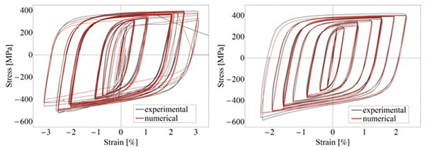
Complex BRB behavior was modeled with the Steel4 numerical material model that was developed by Ádám Zsarnóczay to improve the accuracy and efficiency of BRB modeling [8]. The official source code of Open Sees 2.2.2 has been extended to include Steel4. Steel4 is available in the official OpenSees release since version 2.4.6 [45]. Material parameters had been calibrated using force/displacement data from a total of 15 laboratory experiments. The experiments are described in detail in the corresponding test reports [2, 9], while the calibration is explained in [8]. Fig. (12) shows two example results with calibrated models. Because material properties depend on the brace geometry, each brace in the frame has a specific corresponding material assigned to it.
The effect of low cycle fatigue is considered for braced frame columns and BRB elements. Their materials are wrapped by the fatigue material in OpenSees. The fatigue material uses a modified version of the popular rainflow cycle counting method for counting the number of equivalent cycles in irregular load history. Material damage is accumulated from each cycle based on its deformation amplitude. The widely accepted Coffin-Manson relationship is used to estimate the damage and the point of failure. Fatigue parameters for columns are taken from the work of Uriz [46], while those for BRB elements were calibrated using the aforementioned test results.
3. RESULTS
3.1. Summary of Results for all Archetypes
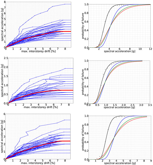
Fig. (13) shows results of design procedure evaluation for three archetypes. Maximum interstory drift values are plotted for each time-history analysis for each archetype on the so-called IDA curves and the median response is highlighted with a red curve. The corresponding fragility curves are also displayed on the right side of each figure. The black curve is based on the results of dynamic analyses. The blue curve is shifted to take the influence of spectral shape into account (using the so-called Spectral Shape Factor).
The extent of additional uncertainty in the results is estimated using the following assumptions:
- Design requirements are considered to be appropriate to safeguard against unanticipated global failure modes, but it is recognized that the design of BRB connections shall be improved by further research on connection behavior. This could increase both the robustness and the confidence in the design procedure. Therefore, βDR in the range of 0.12 – 0.15 is used based on the recommendations of table 3-1 in FEMA P695 [21].
- Available test results (including the ones in the literature) are considered to give a good description of the general behavior of the BRB element and the BRBF as a structure. However, only a limited amount of information is available on BRB behavior under irregular cyclic loading and this might affect the accuracy of the developed numerical model. This effect is considered by using a βTD in the range of 0.18 – 0.23 based on the recommendations of table 3-2 in FEMA P695 [21].
- Although the presented study uses highly accurate numerical models, the number of archetypes considered is not sufficient to state that they cover all possible BRBF representations with high confidence. Further analyses can be used to improve upon this aspect of the research and decrease the assigned uncertainty if necessary. The value of βMDL is set in the 0.18 – 0.23 range.
A lower and higher bound of total uncertainty is calculated from the above values and the red and green curves are the final results on conditional collapse probability for a conservative and unconservative approach, respectively. These curves are used to display results sensitivity to the additional sources of uncertainty. Evaluation is based on the mean of the lower and higher bound values.
| PG | ID | Stories | Frame | Gravity Load | Seismicity | SaD(T1) [g] | SaC(T1) [g] | βRTR | SSF | SaCA(T1) [g] | βTOT | PC|SaMCE [%] | PC [%] | β | Pass/Fail | ||||
|---|---|---|---|---|---|---|---|---|---|---|---|---|---|---|---|---|---|---|---|
| Min | Max | Min | Max | Min | Max | Min | Max | ||||||||||||
| 1 | 11 | 2 | A | Low | Moderate (0.15 g) | 0.5 | 1.37 | 0.30 | 1.20 | 1.66 | 0.41 | 0.47 | 2.63 | 4.55 | 0.010 | 0.014 | 3.64 | 3.72 | pass |
| 12 | 3 | B | 0.43 | 1.01 | 0.32 | 1.23 | 1.24 | 0.43 | 0.48 | 6.43 | 8.66 | 0.028 | 0.036 | 3.38 | 3.45 | pass | |||
| 13 | 3 | A | 0.39 | 0.91 | 0.35 | 1.26 | 1.15 | 0.45 | 0.50 | 6.65 | 8.82 | 0.037 | 0.047 | 3.31 | 3.37 | pass | |||
| mean of the group | 0.32 | 1.23 | 1.35 | 0.43 | 0.48 | 5.24 | 7.34 | 0.025 | 0.032 | 3.443 | 3.513 | PASS | |||||||
| 2 | 14 | 4 | A | Low | Moderate (0.15 g) | 0.32 | 0.80 | 0.37 | 1.31 | 1.04 | 0.47 | 0.52 | 5.00 | 6.85 | 0.059 | 0.073 | 3.18 | 3.24 | pass |
| 15 | 5 | A | 0.28 | 0.66 | 0.36 | 1.37 | 0.91 | 0.46 | 0.51 | 4.64 | 6.48 | 0.046 | 0.058 | 3.25 | 3.31 | pass | |||
| 16 | 6 | A | 0.25 | 0.53 | 0.37 | 1.36 | 0.72 | 0.47 | 0.51 | 8.26 | 9.93 | 0.154 | 0.184 | 2.90 | 2.96 | pass | |||
| mean of the group | 0.37 | 1.35 | 0.89 | 0.47 | 0.51 | 5.97 | 7.75 | 0.086 | 0.105 | 3.11 | 3.17 | PASS | |||||||
| 3 | 21 | 2 | A | Low | High (0.40 g) |
1.35 | 3.43 | 0.28 | 1.34 | 4.59 | 0.39 | 0.45 | 1.79 | 3.45 | 0.096 | 0.121 | 3.03 | 3.10 | pass |
| 22 | 3 | B | 1.35 | 2.98 | 0.28 | 1.36 | 4.05 | 0.40 | 0.45 | 4.16 | 6.17 | 0.115 | 0.143 | 2.98 | 3.04 | pass | |||
| 23 | 3 | A | 1.35 | 2.98 | 0.32 | 1.37 | 4.08 | 0.42 | 0.48 | 4.77 | 7.22 | 0.102 | 0.128 | 3.02 | 3.08 | pass | |||
| mean of the group | 0.29 | 1.36 | 4.24 | 0.40 | 0.46 | 3.57 | 5.62 | 0.104 | 0.131 | 3.01 | 3.07 | PASS | |||||||
| 4 | 24 | 4 | A | Low | High (0.40 g) |
1.35 | 3.13 | 0.27 | 1.39 | 4.35 | 0.39 | 0.44 | 2.50 | 4.11 | 0.051 | 0.065 | 3.21 | 3.28 | pass |
| 25 | 5 | A | 1.19 | 2.55 | 0.22 | 1.44 | 3.68 | 0.36 | 0.42 | 2.22 | 4.25 | 0.070 | 0.088 | 3.12 | 3.19 | pass | |||
| 26 | 6 | A | 1.08 | 2.35 | 0.23 | 1.46 | 3.43 | 0.37 | 0.43 | 2.13 | 4.05 | 0.087 | 0.108 | 3.07 | 3.13 | pass | |||
| mean of the group | 0.24 | 1.43 | 3.82 | 0.37 | 0.43 | 2.28 | 4.14 | 0.069 | 0.087 | 3.13 | 3.20 | PASS | |||||||
Tables 3 and 4 summarize the results of collapse probability evaluation for all archetypes and show the average results for archetypes within each performance group. Lower and upper bound results are included for all variables that are influenced by the magnitude of additional uncertainty.
| PG | ID | Stories | Frame | Gravity Load | Seismicity | SaD(T1) [g] | SaC(T1) [g] | βRTR | SSF | SaCA(T1) [g] | βTOT | PC|SaMCE [%] | PC [%] | β | Pass/Fail | ||||
|---|---|---|---|---|---|---|---|---|---|---|---|---|---|---|---|---|---|---|---|
| Min | Max | Min | Max | Min | Max | Min | Max | ||||||||||||
| 5 | 31 | 2 | A | High | Moderate (0.15 g) | 0.50 | 1.23 | 0.33 | 1.20 | 1.48 | 0.43 | 0.48 | 5.70 | 7.84 | 0.017 | 0.023 | 3.50 | 3.58 | pass |
| 32 | 3 | B | 0.42 | 0.88 | 0.35 | 1.23 | 1.09 | 0.45 | 0.50 | 11.16 | 13.64 | 0.047 | 0.060 | 3.23 | 3.30 | pass | |||
| 33 | 3 | A | 0.39 | 0.76 | 0.36 | 1.26 | 0.95 | 0.46 | 0.51 | 14.59 | 17.09 | 0.068 | 0.085 | 3.14 | 3.20 | pass | |||
| mean of the group | 0.35 | 1.23 | 1.17 | 0.44 | 0.50 | 10.48 | 12.86 | 0.044 | 0.056 | 3.29 | 3.36 | FAIL | |||||||
| 6 | 34 | 4 | A | High | Moderate (0.15 g) | 0.32 | 0.67 | 0.34 | 1.31 | 0.88 | 0.44 | 0.50 | 8.42 | 11.27 | 0.091 | 0.112 | 3.05 | 3.12 | pass |
| 35 | 5 | A | 0.27 | 0.55 | 0.33 | 1.36 | 0.75 | 0.43 | 0.48 | 7.59 | 9.96 | 0.115 | 0.140 | 2.99 | 3.05 | pass | |||
| 36 | 6 | A | 0.25 | 0.50 | 0.35 | 1.37 | 0.69 | 0.45 | 0.50 | 8.77 | 11.13 | 0.101 | 0.122 | 3.03 | 3.09 | pass | |||
| mean of the group | 0.34 | 1.35 | 0.77 | 0.44 | 0.49 | 8.26 | 10.79 | 0.102 | 0.125 | 3.02 | 3.09 | PASS | |||||||
| 7 | 41 | 2 | A | High | High (0.40 g) |
1.35 | 3.17 | 0.29 | 1.34 | 4.26 | 0.40 | 0.46 | 3.15 | 5.30 | 0.115 | 0.143 | 2.98 | 3.04 | pass |
| 42 | 3 | B | 1.35 | 2.81 | 0.29 | 1.36 | 3.83 | 0.41 | 0.46 | 6.00 | 8.30 | 0.132 | 0.164 | 2.94 | 3.01 | pass | |||
| 43 | 3 | A | 1.35 | 2.93 | 0.30 | 1.37 | 4.02 | 0.41 | 0.47 | 4.72 | 7.23 | 0.100 | 0.124 | 3.02 | 3.08 | pass | |||
| mean of the group | 0.29 | 1.36 | 4.04 | 0.41 | 0.46 | 4.63 | 6.94 | 0.116 | 0.144 | 2.98 | 3.04 | PASS | |||||||
| 8 | 44 | 4 | A | High | High (0.40 g) |
1.35 | 3.30 | 0.25 | 1.39 | 4.59 | 0.37 | 0.43 | 1.35 | 2.85 | 0.038 | 0.050 | 3.29 | 3.36 | pass |
| 45 | 5 | A | 1.21 | 2.57 | 0.22 | 1.44 | 3.71 | 0.36 | 0.42 | 2.35 | 4.44 | 0.066 | 0.084 | 3.14 | 3.21 | pass | |||
| 46 | 6 | A | 1.04 | 2.19 | 0.24 | 1.47 | 3.22 | 0.37 | 0.43 | 2.51 | 4.60 | 0.108 | 0.133 | 3.00 | 3.07 | pass | |||
| mean of the group | 0.24 | 1.43 | 3.84 | 0.37 | 0.43 | 2.07 | 3.96 | 0.071 | 0.089 | 3.14 | 3.21 | PASS | |||||||
In general, seismic performance of the performance groups is satisfactory, namely that the conditional probability of failure of their structures at the MCE intensity is typically less than 10%. The majority of individual collapse probabilities of the archetypes are also below 10% and all of them are below 20%. The average collapse probability of performance group PG-5 is 11.67%, slightly higher than the prescribed limit; however, the authors consider this result acceptable, although further study with the extension to additional archetypes is recommended.
Note that the record to record variability for BRBF archetypes is in the range of 0.23 – 0.37 with a median value of 0.32. This is significantly smaller variation in response than the 0.4 suggested by FEMA P695 developers. There is considerable difference between results with the constant 0.4 variability and the more accurate evaluations based on direct fitting of fragility curves. Therefore, further investigation of this topic is needed through the analysis of other types of BRBF and other steel frame solutions to understand the limits of the assumed constant standard deviation. Until these limits are identified, it is recommended for other researchers to use the direct evaluation method for fragility curve definition, because it provides results with good accuracy even for small sample sizes.
Probabilities of collapse over the lifetime of structures and the corresponding reliability indices do not fulfill the limits in EC0 for Ultimate Limit State design. Note that it is only possible to achieve the 0.01% probability of failure prescribed by EC0 if the designed structure does not certainly collapse from ground motions with 0.01% probability of occurrence. Such a ground motion is extremely rare (e.g. 4975 year return period hazards have 1% probability of occurrence in 50 years) and the authors reason that it is not economical to design a structure to resist such rare effects. This observation has been made by other researchers as well [33]. It is also important to consider that other dissipative solutions such as special concentrically braced frames have been shown to fail this criterion and have inferior performance to BRBF [47]. Therefore, further research is recommended on this topic that involves multiple types of standardized anti-seismic solutions to assess the probability of structural failure that is already accepted by including those systems in the standard. Based on those values, the rigorous limits of EC0 shall be relaxed for seismic performance evaluation.
DISCUSSION AND CONCLUSION
The high ductility and large energy dissipation capacity of Buckling Restrained Braces make them excellent elements for dissipative structural solutions. These properties combined with an appropriate design procedure lead to the good performance of Buckling Restrained Braced Frames. The presented results suggest that the proposed methodology enables the application of a behavior factor of 7 for the design of all BRBF structures within the scope of this research. The conservative considerations applied in both numerical modeling and uncertainty estimation provide high confidence in the collapse assessment results. Note that according to the FEMA P695 methodology, a peer review panel shall review the proposed design procedure and the presented results before further steps could be taken towards standardization.
Based on the presented results the procedure presented in section 2.3 and explained in detail in Vigh et al. [42] and Zsarnóczay et al. [8] is considered appropriate for BRBF design with the following limitations:
- The braced frame is concentrically braced with pinned diagonal braces and pinned beams.
- The braced frame has diagonal braces in a two-bay X-brace configuration.
- All columns of the frame are continuous. The columns of the braced frame have fixed; other columns of the gravity frame have pinned support.
- The number of stories ranges from 2 to 6 and the height of the structure ranges from 8 to 24 meters. Archetypes were regular in both plan and elevation with no significant torsional effects involved in the design. The influence of irregularity on structural behavior needs to be considered in design.
- The slope of diagonal braces is in the 25° – 40° range.
- The braced floor area corresponding to each braced frame in the structure is within the range of 2b2 and 4b2 where b is the distance between the outer columns of the braced frame.
- The design peak ground acceleration is less than or equals to 0.4 g.
Future research shall focus on investigation of additional archetypes and enhancement of the applied seismic performance evaluation methodology. The latter shall adjust the inputs and outputs of the methodology to the European design environment as well as improve its reliability by incorporating recent developments in seismic performance assessment. These enhancements will lead to a better understanding of BRBF behavior and allow relaxation of the above limits of the proposed design procedure.
CONFLICT OF INTEREST
The authors confirm that this article content has no conflict of interest.
ACKNOWLEDGEMENTS
The work reported in the paper has been developed in the framework of the “Talent care and cultivation in the scientific workshops of BME” project. This project is supported by the grant TÁMOP-4.2.2.B-10/1-2010-0009. This paper was also supported by the János Bolyai Research Scholarship of the Hungarian Academy of Sciences. The authors would also like to express their gratitude to Star Seismic Europe Ltd. for providing the support they provided for this research.


