All published articles of this journal are available on ScienceDirect.
Numerical and Analytical Modeling for Predicting Drag Load Induced on Pile in Collapsible Soil because of Inundation
Abstract
Introduction:
Negative skin friction that develops on the pile surface when the soil (adjacent to the pile shaft) settles but the pile is in static condition, causes an additional load (known as drag load) induced on pile. Substantial settlement of collapsible soil occurs only because of inundation. In such a case, the magnitude of drag load is influenced by several parameters, such as the collapse potential, inundation pressure, pile roughness, pile diameter, radius of wetting, depth to the neutral plane, and thickness of collapsible soil subjected to inundation.
Methods:
A numerical model is developed to simulate the case of a single pile in collapsible soil to predict negative skin friction and drag load by giving consideration to kinetic friction angle between the pile and the settling soil. The comprehensive interdependent relation among the parameters influencing the magnitude of drag load was revealed based on numerical results. Analytical models are developed for predicting the average negative skin friction and depth of neutral plane to quantify drag load because of the inundation of collapsible soil adjacent to the pile shaft.
Result and Conclusion:
The model coefficients were determined by analyzing the numerical results. The drag loads obtained from the analytical model developed and those from previous experimental studies are found in good agreement. For a given soil profile, the magnitude of drag load is found to vary widely (e.g., between 252 and 925 kN) because of the variations in the pile diameter, pile roughness, and radius of wetting. Thus, this study provides a design guideline for choosing the design pile diameter considering the magnitude of drag load due to inundation of collapsible soil adjacent to the pile shaft.
1. INTRODUCTION
Drag load that is induced on pile as an additional load due to negative skin friction developed on the pile surface, which needs to be considered in pile design [1-4]. If drag load is not considered in design, it may cause serious damage to structures and might perhaps even lead to catastrophic failure. Piles in collapsible soil, soft clay and liquefiable soil may experience drag load due to inundation [3, 5-7], consolidation [2, 8-12] and liquefaction [2], respectively. Lowering of the ground water table around the pile shaft can also cause drag load [13]. In such cases, pile foundation is often considered the only alternative to transfer loads to the stable soil strata. This is because different soil improvement measures are available, but the extent to which the soil improvement attained in the field condition would adequately minimize the problem of foundation settlement has not been revealed.
The term ‘negative skin friction’ is for pile skin friction if it acts downward. Negative skin friction is a kinetic friction that may develop on some part of the pile shaft when the pile is in static condition but the soil (adjacent to the pile shaft) experiences settlement [5, 6]. Conventionally, pile skin friction acting upward is termed ‘positive skin friction’, as it resists the vertical downward load applied on the pile. Positive skin friction is a static friction, as it develops when both the pile (acting under axially downward load) and the adjacent soil are in static condition. In physics, kinetic friction is smaller than static friction. To date, this issue has not been considered in modelling the drag load induced on pile in collapsible soil because of inundation.
Collapsible soil experiences substantial volume reduction suddenly because of inundation only without any change in the applied soil stress [3, 5-7]. Collapsible soil was observed to collapse by 10% of its volume when soaked, though it settled negligibly in its dry state under a stress of 670 kPa in excess of the natural overburden stress [14]. Ground inundation can be caused by leakage of an underground reservoir or broken pipes, heavy rain, or rise in the groundwater table.
In this study, the case of a single pile in collapsible soil is numerically modeled to predict negative skin friction and drag load during inundation of collapsible soil by giving consideration to kinetic friction angle between the pile and the settling soil. A numerical investigation is carried out to reveal the interdependent relation among the parameters influencing the magnitude of the drag load. Analytical models are proposed to predict the average negative skin friction and depth of neutral plane to quantify the drag load. Another model is developed to obtain the drag load for different pile roughnesses, represented by the kinetic friction angle at the pile-soil interface, where negative skin friction develops. This study provides a design guideline for choosing the pile design diameter considering the magnitude of drag load due to inundation of collapsible soil adjacent to the pile shaft.
2. NEGATIVE SKIN FRICTION, DEPTH OF NEUTRAL PLANE AND DRAG LOAD
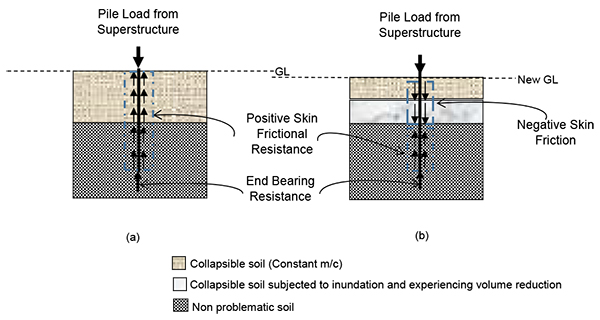
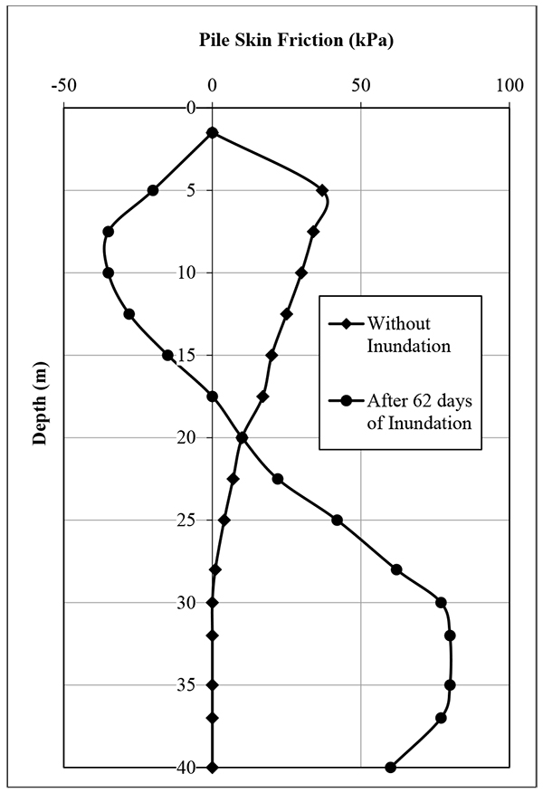
Pile load transfer mechanism depends on the stability of the soils adjacent to the pile shaft, as schematically shown in Fig. (1). In the case of Fig. (1a), the soil is stable, and hence only positive skin friction (i.e., static friction) develops on the pile surface. This can also be a case of piles in collapsible soil having constant moisture content. On the other hand, the scenario of pile load transfer is quite different in the case of Fig. (1b), at which a portion (i.e., a thickness of Hs) of a collapsible soil layer (at some depth) which is subjected to inundation, settles faster than the pile. In such a case, negative skin friction develops in the upper portion of the pile, from the pile head up to a location on the pile surface (termed neutral plane), where no relative movement occurs between the pile and the adjacent soil. Therefore, in the cases where collapsible soil experiences inundation induced settlement, both the negative and positive skin frictions develop at the pile soil interface, as shown in Fig. (1b). The magnitude of negative skin friction is zero at the pile head and on the neutral plane, while varying between these two locations. Pile skin friction changes from negative skin friction to positive shaft resistance at the neutral plane. Thus, the drag load increases from zero at the pile head and reaches its maximum value at the neutral plane below which positive shaft resistance develops and the pile load decreases consequently. Fig. (2) presents the comparison between the typical pile skin friction distributions for both the conditions of collapsible soil.
The depth of neutral plane (HN.P) and the pile perimeter defines the pile surface area where negative skin friction develops. Therefore, the magnitude of drag load can be calculated as below
 |
(1) |
where P and qn denote the pile perimeter and the average negative skin friction, respectively.
3. LITERATURE REVIEW AND PRESENT STATUS: PREDICTION OF DRAG LOAD
The amount of inundation induced settlement of collapsible soil, with which the magnitudes of negative skin friction and drag load are directly related, depends on several parameters, including collapse potential, zone of wetting (radial and vertical coverages), pile diameter, and inundation pressure. Recording drag loads from the tests on full-scale instrumented piles is a lengthy process, as negative skin friction or pile axial load is measured at different depths during the period the collapsible soil layer is artificially inundated. The drag loads induced on full-scale instrumented piles in collapsible soils because of inundation are reported in the literature [5, 6]. Due to lack of field data as compared to the number of parameters, the combined effect of the parameters on the magnitudes of negative skin friction and drag load remains undiscovered. Model pile in collapsible soil was tested to record drag load induced on the pile due to inundation [15]. However, application of the outcome of model/scaled tests is limited in practice, as the negative skin friction developed on the model pile-soil interface is different from that developed on the similar pile-soil interface of a full-sized pile at field condition.
A numerical procedure is available for predicting drag load induced on pile in collapsible soil [3]. In that procedure, for all the pile-soil interface elements, the angle of friction was considered 0.9φ´ that corresponds to the angle of static friction for bored cast-in-situ pile. Their study did not address the fact that negative skin friction develops on the pile surface as kinetic friction. As the study considered only the cases, in which the variable parameters were close to their lower limits of their respective practical ranges, good agreements between the experimental and the numerical results were found without addressing this issue. Moreover, the constraints of using the equation given in [3] are that radius of wetting (h) was kept constant, and collapse potential was varied up to 10% only, while developing the equation. In addition, the depth of neutral plane was assumed to develop at the bottom of the collapsing soil. Moreover, thickness of collapsible soil subjected to inundation, radius of wetting and pile roughness were not considered the variable parameters in the analytical model given in [4] for predicting drag load induced on end bearing pile in collapsible soil.
4. NUMERICAL MODEL
An axisymmetric finite element model of a single vertical pile is developed to predict negative skin friction for quantifying the drag load. The vertical boundaries were restrained in the horizontal direction, but free to move in the vertical direction. The bottom of the mesh is restrained in both the horizontal and the vertical directions. Therefore, the vertical settlements of the pile and the soil can occur because of external load and/or the occurrence of inundation of collapsible soil. The centerline of the mesh coincides with the axis of the pile. Both the soil and the pile clusters were meshed with the 15-node triangular element, giving a fourth order interpolation for displacements. Five-node line elements were used at the pile-soil interface to account for the relative pile-soil movement. The generated mesh, as shown in Fig. (3), was of medium coarseness using the software PLAXIS 2D [16]. By refining mesh around the pile, a large number of nodes, as compared to the global coarseness, were provided in the vicinity of the pile’s shaft, where deformations and stresses generally take place.
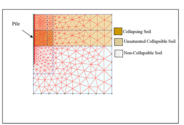
Pile material was modeled as non-porous material with Linear-Elastic (isotropic) constitutive relationship, requiring only two input parameters: Young’s modulus (Ep) and Poisson’s ratio (υp). The constitutive law of the soil was defined by Mohr-Coulomb (MC) failure criterion, requiring five material parameters; including cohesion (c), angle of internal friction (φ), angle of dilatancy (ψ), modulus of elasticity (E) and Poisson’s ratio (υ). The behavior of the pile-soil interface was also defined by the MC Model.
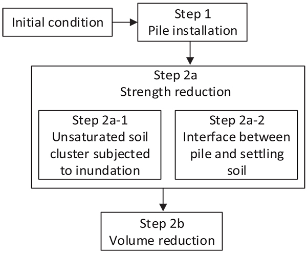
In simulating the inundation of collapsible soil, the procedure given in [3] proposed to carry out the finite element calculation in three steps [Steps 1, 2a and 2b]. Step 1 was for installation of the pile, step 2a was to incorporate the effect of strength reductions due to inundation, and Step 2b was to simulate volume reduction of collapsible soil subjected to inundation. While detailing out Step 2a, that study addressed only the soils that underwent significant reductions in the initial shear strength parameters.
As the present study simulates the scenario of inundation taking place within the collapsible soil layer (in contact with the pile shaft), the changes in the aspects of collapsible soil due to inundation are considered in developing the numerical model. It is to note that the values of c and φ (i.e., two input parameters) decrease, as matric suction decreases during inundation. Moreover, the friction angle (δ) between the pile and the soil that is the main factor to control the magnitude of pile skin friction, also decreases during inundation. In the simulation of the present study, these two aspects are addressed in two steps [Step 2a-1 and Step 2a-2], as shown in Fig. (4). Step 2a-1 is to address the strength reduction of unsaturated soils due to inundation, as described in [3]. It was previously noted that reduction in φ value of the soil adjacent to the pile shaft has minor influence on the magnitude of drag load, as calculated from the PLAXIS output. Therefore, Step 2a-2 is necessary to incorporate the required adjustment of the input parameters’ values for pile interface elements to address the changes in the value of δ.
The strength parameters of each pile-soil interface element are obtained from those of the soil in contact with the pile surface, according to the δ/φ ratio (i.e., termed interface strength reduction factor, ISRF). Where both the pile and the adjacent collapsible soil are in static condition, ISRFstatic represents the δs/φcs ratio that usually ranges between 0.7 and 1 depending on the method of pile installation. Instead, where negative skin friction develops on the pile surface because of the soil experiencing settlement, ISRFkinetic (i.e., δk/φcs) is applied to determine the strength parameters of the pile-soil interface element. As the ratio δk/δs usually ranges between 0.5 and 0.8 for the interfaces between different materials [17], ISRFstatic may be reduced by 20 – 50% to obtain ISRFkinetic. Here, the friction angle between the pile and the soil is denoted by δs when both the pile and the soil are in static condition, and by δk when the soil is settling faster than the pile.
In Step 2b, the cluster of collapsible soil, subjected to volume change during inundation, is assigned a volumetric strain (-ve) parameter, which is derived from the collapse strain attained (εc) in field condition. The correlation between volumetric strain and collapse strain is given in [3].
The above numerical model was employed to derive the mathematical functions that define the coefficients of analytical models developed in this study. Hence, the case of a single-vertical pile was modelled for different pile dimensions, soil properties, and inundation conditions, as listed in Table 1.
| Parameters | Unit | Range |
|---|---|---|
| Cohesion (c) of collapsible soil | kPa | 20 |
| Angle of internal friction (φcs) of collapsible soil | ° | 20–40 |
| Collapse potential (Cp) | % | 5–15 |
| Angle of internal friction (φ) of dense sand | ° | 40 |
| Thickness of collapsible soil layer (H) | m | 8–15 |
| Depth of collapsing soil (Hs) | m | 4–7.5 |
| x = Hs/H | - | 0.5 |
| Length of pile (L) | m | 12–30 |
| Diameter of pile (D) | m | 0.2–1 |
| Pile length-to-diameter ratio (L/D) | - | 20–75 |
| Embedded pile length into noncollapsible soil-to-full pile length ratio (Le/L) | - | 0.3–0.75 |
| Radius of wetting (h) | m | 3–10 |
| Interface strength reduction factor (ISRF) | - | 0.6–0.9 |
5. ANALYTICAL MODEL
In this study, average negative skin friction (qn) and depth of neutral plane (HN.P) are analytically modelled to predict drag load using Eq. (1).
The value of qn is directly proportional of Cp of the soil subjected to inundation. This is because the greater the Cp, the greater the settlement (i.e., causing greater magnitude of qn) is. In addition, the amount of settlement also depends on the extent of inundation (described as Hs and h in Fig. (1)) around the pile. Therefore, Cp, Hs, h and pile diameter (D) are the parameters that may influence negative skin friction developed on the pile surface. However, there exists an upper limit of collapse potential (denoted by Cp(max)) up to which the value of qn increases proportionally with Cp. Thus, the following equation is proposed by introducing a proportional coefficient (k), which is also a function of Hs, h and D.
 |
(2) |
where k = f(Hs, D, h).
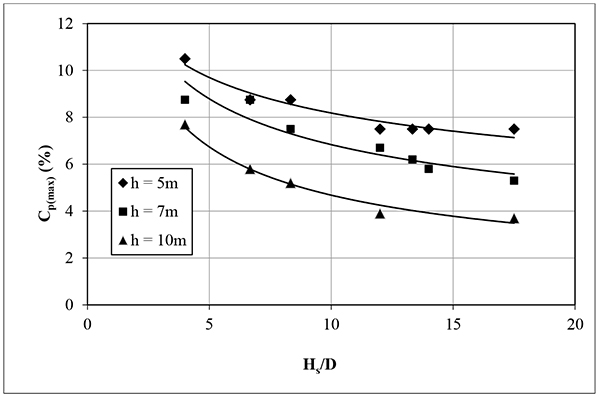
The value of CP(max) depends on the parameters Hs, D and h. For a given set of Hs, D and h, if Cp(max) is less than the Cp of the soil experiencing volume reduction, qn will be caused by Cp(max), instead of CP.
Further, Cp, h, and Hs are the parameters that may influence HN.P. However, the vertical extent of inundation (Hs) influences HN.P more than the other two parameters (CP and h). Thus, the following equation is proposed by introducing another proportional coefficient (m), which depends on Cp and h:
 |
(3) |
where m = f(Cp, h).
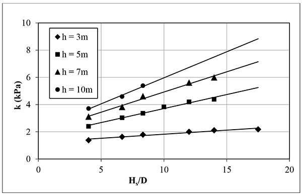
The value of the proportional coefficient k in Eq. (3) is obtained, as shown in Fig. (5), for different Hs, D and h. The value of k increases, as Hs/D increases. Moreover, the value of k increases as the radius of wetting (h) increases, for a given Hs/D. The variation in Cp(max) according to Hs/D for different values of h is obtained, as shown in Fig. (6). The mathematical function of coefficient m is formulated in Eq. (4) for different pile dimensions, soil properties, and inundation conditions as listed in Table 1.
 |
(4) |
The ratio of the drag load on a pile of given roughness to that on a pile having an ISRFkinetic of 0.9, is defined as below:
 |
(5) |
where, both Im and Ic are the fitting parameters, and Qn(0.9) is termed as the base value of drag load on pile having ISRFkinetic of 0.9.
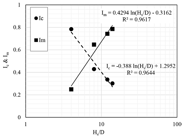
Based on the numerical results for different pile/soil/inundation conditions, both Im and Ic are found to have linear relationships with Hs/D in semi-logarithmic plot, as shown in Fig. (7).
6. VALIDATION OF ANALYTICAL MODEL
The predicted values from the proposed analytical models were compared with the results of the model pile tests reported in [15]. The model pile, made of stainless steel and having a diameter of 0.0254 m, was 1.5 m long, of which 0.5 m ± 0.03 was embedded in the collapsible soil. The pile was installed as an end-bearing type pile at the middle of the testing tank, having an area of 0.25 m2 and 0.6 m high. The pile was partially fixed to a load cell that rested on the bottom of the tank and restrained from movement. Model pile tests were conducted to measure the drag load acting on the pile’s shaft due to sudden volume reduction of a collapsible soil layer subjected to inundation from the bottom.
Table 2 presents the comparisons between the predicted values from the analytical models and experimental results for half depth inundation from the bottom. For the cases where ISRFkinetic was employed 0.5, the deviations of the predicted values fall within 15% from the experimental results, as given in Table 3. This comparison establishes that the prediction of drag load should consider ISRFkinetic, which was found to be 70% of ISRFstatic.
| Test | q n (kPa) | ||||
|---|---|---|---|---|---|
| Analytical (present study) | Experimental [3] | ||||
|
Base Value (ISRF= 0.9) |
ISRF = 0.7 | ISRF = 0.6 | ISRF = 0.5 | ||
| 1 | 13.6 | 11.9 | 11.0 | 10.1 | 10.5 |
| 2 | 16.9 | 14.8 | 13.6 | 12.8 | 11.3 |
| 3 | 22.0 | 19.3 | 17.8 | 16.1 | 14.0 |
| 4 | 9.9 | 8.7 | 8.0 | 7.1 | 6.3 |
| Test | Deviation (%) between predicted and experimental qn | |||
|---|---|---|---|---|
|
Base Value (ISRF= 0.9) |
ISRF=0.7 | ISRF=0.6 | ISRF=0.5 | |
| 1 | 29 | 13 | 4 | -4 |
| 2 | 50 | 31 | 21 | 13 |
| 3 | 57 | 37 | 27 | 15 |
| 4 | 57 | 38 | 27 | 13 |
The proposed analytical model is validated using the experimental result of full-scale pile reported in [5]. The pile, tested in Volgodon-2, was 18 m long (bored and cast in situ type), having a diameter of 1 m. The collapsible soil, having Cp of 8%, was found up to the depth of 15 m from the ground level. Local wetting of collapsible soil was induced after the pile was installed using a circular trench, having four vertical drainage holes (0.17 m in diameter and 16 m in length) at the bottom.
Good agreements are obtained between the predicted values from the analytical model and experimental results (full-scale test), as given in Table 4.
7. DESIGN GUIDELINE
The following steps can be used to predict drag load as a design guideline:
- Choose different pile diameters and radii of wetting to obtain alternative designs.
- Find the Hs/D for each pile. Here, Hs = thickness of collapsible soil subjected to inundation.
- For each set of Hs/D and h, determine the values of k and CP(max) using Figs. (5 and 6), respectively.
- Calculate the values of qn and HN.P using Eq. (2) and Eq. (4), respectively.
- Calculate the base value of drag load (Qn(0.9)) using the values calculated in Step 4 in Eq. (1).
- Obtain ISRFkinetic as 25 to 30% less than ISRFstatic (i.e., δs/φ).
- Calculate the drag load using Eq. (7) of which two fitting parameters (Ic and Im) are obtained from Fig. (7).
8. DESIGN EXAMPLE
A single pile, as shown in Fig. (1b), is designed to demonstrate the proposed design guideline:
- Depth of collapsible soil, H = 12 m;
- Thickness of collapsible soil subjected to inundation, Hs = 6 m; and
- Collapse potential, Cp = 8%.
1. In Step 1, pile diameters and radii of wettingtable
- Different pile diameters are chosen between 0.3 to 1 m to obtain alternate designs.
- Two radii of wetting of 5 m and 7 m are considered.
2. In Step 2, calculate Hs/D
3. In Step 3, obtain CP(max) and k
- Both CP(max) and k are determined for different pile diameters and both radii of wetting, as given in Table 5.
| D (m) | Hs/D | CP(max) (%) | k (kPa) | qn (kPa) for ISRF = 0.9 | Qn (kN) for ISRF = 0.6 | ||||
|---|---|---|---|---|---|---|---|---|---|
| h = 5 m | h = 7 m | h = 5 m | h = 7 m | h = 5 m | h = 7 m | h = 5 m | h = 7 m | ||
| 0.3 | 20 | 6.9 | 5.3 | 5.8 | 7.9 | 39.8 | 41.9 | 253 | 278 |
| 0.45 | 13.3 | 7.6 | 6.2 | 4.4 | 5.9 | 33.5 | 36.4 | 342 | 389 |
| 0.6 | 10 | 8.2 | 6.8 | 3.7 | 4.9 | 29.7 | 33.6 | 424 | 503 |
| 0.8 | 7.5 | 8.8 | 7.6 | 3.2 | 4.2 | 25.5 | 31.7 | 509 | 661 |
| 1 | 6 | 9.3 | 8.2 | 2.9 | 3.7 | 23.1 | 29.9 | 595 | 807 |
4. In Step 4, calculate average negative skin friction and depth of neutral plane
- Average negative skin friction (qn) is calculated for the different pile diameters, as given in Table 5.
- The depth of neutral plane is calculated 9.4 m and 9.9 m for the radii of wetting of 5 m and 7 m, respectively.
5. In Step 5, calculate the base value of drag load
 |
- The base value of drag load (Qn(0.9)), which is calculated for different piles, ranges between 353 to 682 kN and between 388 to 925 kN for radii of wetting of 5 m and 7 m, respectively.
6. In Step 6, determine ISRFkinetic
- ISRFkinetic is obtained 0.6, which is 30% smaller than ISRFstatic of 0.85.
7. In Step 7, calculate drag load
Drag load is calculated for different pile diameters and both the radii of wetting, as given in Table 5.
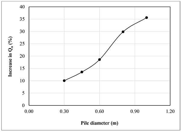
For any pile diameter, greater radius of wetting is found to cause greater drag load. Moreover, this increase in Qn (in percent) is found consistent for a given diameter of pile having any ISRFkinetic, as shown in Fig. (8). A pile having 0.6 m diameter or less may be chosen as the design pile diameter (Fig. 8).
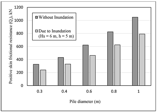
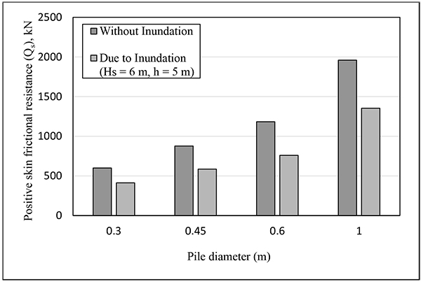
The magnitude of Qn depends only on Cp, pile diameter (D) and the dimensions of collapsing zone (defined by Hs and h), but not on the pile length (L). Instead, the magnitude of Qs depends on both pile diameter and pile length, especially the portion of the pile below the neutral plane (i.e., L – HN.P). The effects of inundation on Qs (i.e., developed on the pile surface below the neutral plane) are compared in Figs. (9 and 10), as obtained by using the numerical model, for the given case of inundation and collapsible soil profile overlying medium dense sand. In this respect, the values of Qs for two different pile lengths (such as 12 m and 18 m) are studied for different pile diameters used to calculate Qn in Table 5. It can be noted that each pile suffers from the reduction in skin frictional resistance due to inundation induced soil collapse adjacent to the pile shaft. Thus, piles, having contact with collapsing soil, suffer from reduction in pile capacity due to reduction in Qs.
CONCLUSION
The magnitude of the drag load caused by inundation-induced soil collapse adjacent to the pile shaft depends on several parameters, while most of these parameters are not related to the development of drag load due to consolidation or liquefaction. In this study, numerical model is developed considering all the parameters influencing the magnitude of drag load and the fact that negative skin friction is a kinetic type of friction. The analytical models are developed to quantify the drag load at the design stage. The design guideline, presented in this paper, will allow the foundation designers to optimize the pile design diameter.
CONSENT FOR PUBLICATION
Not applicable.
CONFLICT OF INTEREST
The authors declare no conflict of interest, financial or otherwise.
ACKNOWLEDGEMENTS
Declared none.


