All published articles of this journal are available on ScienceDirect.
Design of Direct Embedment Foundations for Poles Under Moment Loads in Granular Soils
Abstract
Introduction:
The design of direct embedment pole foundations involves calculating the ultimate moment capacity and deflections/rotations of pole foundations at groundline.
Methods:
A theoretical model based on rigid piles is used as a basis for developing equations for the ultimate moment capacity of direct embedment pole foundation installed in granular soils.
Results and Conclusion:
The steps involved in the development are presented in this paper. Prototype test data are used to compare the predictions of the model and to validate the proposed method.
1. INTRODUCTION
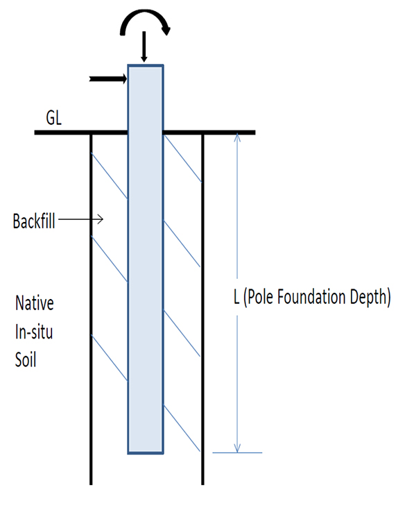
Direct embedment of a pole implies that the borehole prepared has a diameter larger than the pole and that the annular space between the pole and the borehole is backfilled with excavated native soils or select granular backfill materials. A typical direct embedment pole foundation is shown in Fig. (1). The design of these foundations involves the calculation of ultimate moment capacity and deflections/rotations of the pole foundation at ground line.
The depth of embedment is the main design parameter for these pole foundations. The required embedment depth depends on several factors such as:
- geotechnical properties of the backfill and native in-situ soil
- pole diameter
- diameter of the backfill hole
- loading on the pole
In the US utility industry, a rule of thumb is typically used for determining the depth of embedment. Per this rule, the pole foundation depth is given by,
 |
(1) |
where:
L = pole foundation embedment depth (m)
X = empirical depth adder (m)
The pole length is in the units of meters and the typical value of X is 0.61 m (2 ft). However, several utilities use higher adder values based on their internal standards. The obvious shortcoming of this methodology is that the pole embedment depth does not consider any of the factors listed above and thus is not based on sound engineering principles.
A semi-empirical theoretical model was developed [1] for direct embedment foundations and this model is included in the software program called MFAD TM [2]. The MFAD stands for Moment Foundation Analysis and Design and this software is used by several US utilities.
In this paper, a theoretical model developed for the design of direct embedment pole foundations under moment loads installed in granular soils is discussed in detail. This method is useful for preliminary design of direct embedment pole foundations using simple long-hand calculations. This theory was originally developed by the authors as a part of the CEA Report [3].
2. THEORETICAL MODEL
A typical pole foundation subjected to moment loads essentially behaves as a rigid pile under lateral/moment loads (hence in this paper rigid pile and pole foundation used synonymously). However, the interaction between the backfill and native in-situ soil complicates the analysis of these pole foundations. The theory developed to estimate the ultimate lateral/moment resistance of a rigid pile in two different soil media (i.e. backfill and native in-situ soil) is discussed in this section.
Most of the theories proposed for the calculation of the lateral capacity of rigid pile are based on the theory of earth pressure on a rigid retaining wall. The ultimate lateral resistance per unit width of a rigid pile is greater than that of a corresponding wall due to the shearing resistance on the vertical sides of the failure wedges in the soil [4].
Basic rigid pile theories are discussed from fundamentals first and later extended to direct embedment pole foundations considering both backfill and native in-situ soils. The sequence of development is presented in four major steps:
Step 1: Theory of passive earth pressure of a long rigid wall
Step 2: Extension of the theory in Step 1 to rigid piles
Step 3: Passive earth pressure on a long rigid wall with two different soil media (i.e. backfill and native in-situ soil)
Step 4: Extension of the theory in Step 3 to Rigid Piles in two different soil media (i.e. backfill and native in-situ soil)
The last step is basically applicable to direct embedment pole foundations.
2.1. Step 1: Theory of Passive Earth Pressure of a Long Rigid Wall
This theory was originally developed by Coulomb [5]. Fig. (2) shows the retaining wall under passive earth pressure conditions. At the point of failure, a wedge of soil ABC is under the equilibrium of three forces:
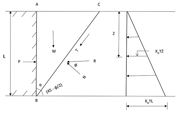
- The resultant passive force, P
- The weight of the wedge, W
- The resultant reaction, R between the wedge and the rest of the soil along the surface BC.
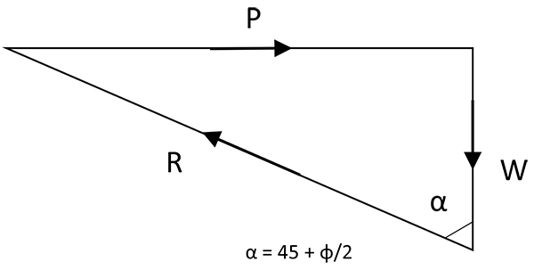
The reaction force R is the resultant of the shear force T and the normal force N. In Fig. (3), force polygon of the above system is shown. It can be shown that the failure wedge BC makes an angle of (45- ϕ/2) with the horizontal and hence the angle α is equal to (45 + ϕ/2). From the figure, the value of the P is calculated as:
 |
(2) |
where:
W= weight of the wedge per unit length of the wall (see Equation 3 below)
ϕ = effective angle of internal friction of granular soil
 |
(3) |
Hence, the total passive force, P is given by,
 |
(4) |
This force, P is thus equivalent to triangular earth pressure distribution on the wall as shown on the right-hand side of Fig. (2). The passive pressure on the wall at any depth, Z, is given by:
 |
(5) |
where:
Kp = passive earth pressure coefficent = 
2.2. Step 2: Extension of the Theory in Step 1 to Rigid Piles
As indicated earlier, the ultimate lateral resistance per unit width of a rigid pile is greater than that of a corresponding wall, due to the shearing resistance on the vertical sides of the failure wedges in the soil. Using the same distribution of earth pressure at failure of the pile as was assumed for the wall, the three-dimensional effect for a pile can approximately be taken into account by multiplying the net earth pressure on a wall by shape factor (Sf).
The pressure distribution on a rigid pile at any depth z can be calculated by multiplying Equation 5 with the shape factor.
 |
(6) |
Typical shape factors adopted by a few investigators for a rigid pile, with depth of L and width of B, are summarized in Table 1.
2.3. Step 3: Passive Earth Pressure on a Long Rigid Wall with Two Different Soil Media (i.e. Backfill and Native In-Situ Soil)
In Fig. (4), a rigid long retaining wall with two different soil media is shown. The height of a retaining wall is L and the thickness of the annular space around the pole is ‘w’. The following assumptions are made:
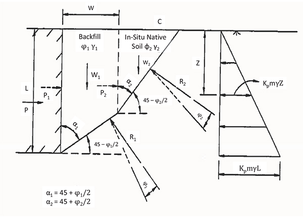
- The vertical face of the wall is smooth
- The backfill soil is stronger than the in-situ native soil
- The failure wedges formed in the two soil media makes an angle of 45- ϕ1/2 and 45- ϕ2/2 (ϕ1 = effective angle of internal friction of backfill soil & ϕ2 effective angle of internal friction of native in-situ soil)
- The total passive force can be equated to the passive force developed due to the individual failure wedges of backfill and in-situ native soil
 |
(7) |
where:
 |
(8) |
 |
(9) |
In the above equations, the weights of wedges in backfill and in native in-situ soil are W1 and W2 respectively and they can be expressed as follows,
 |
(10) |
 |
(11) |
Substituting W1 and W2 values in eq (7) above, the total passive force is given by,
 |
(12) |
Simplifying Equation (12) by substituting w = nL (n = ratio between thickness of backfill behind the wall and the height of the retaining wall) and γ1 = γ2 = γ:
 |
(13) |
where,
 |
(14) |
In the above equation, Kpm is the modified passive earth pressure coefficient. Equation (13) for P is very similar to the earlier Equation (4). Assuming the triangular soil pressure distribution, the passive earth pressure at any depth, z is given by,
 |
(15) |
In the above equation, γ is assumed to be the average of unit weights of backfill and native in-situ soil.
2.4. Step 4: Extension of the Theory in Step 3 to Rigid Piles in Two Different Soil Media (i.e. Backfill and Native In-Situ Soil)
As noted above, the theory and associated equations developed in Step 4 are applicable to direct embedment pole foundations. The following are the assumptions made:
- The theory proposed in Step 3 above can be extended to the rigid pile using appropriate shape factor
- The shape factor is of constant value 3.7 as used by Petrasovits and Award [7] for rigid piles.
- The type of distribution assumed was similar to the one presented by Petrasovits and Award [7] for rigid piles.
- The active earth pressure effect behind the back of the pile is neglected.
By extending Equation (15), the pressure distribution on a rigid pile at any depth z is given by (see Fig. 5),
 |
(16) |
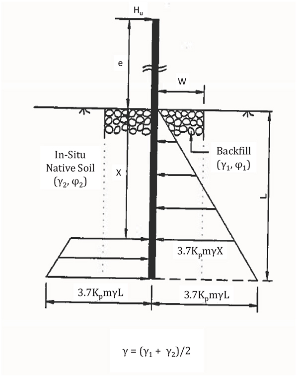
From the horizontal force equilibrium and moment equilibrium of forces shown in Fig. (5), the ultimate lateral resistance Hu and ultimate moment resistance Mu are calculated using the equations shown below.
 |
(17) |
 |
(18) |
L = embedment depth of pole (m)
γ = average of unit weights of backfill and native in-situ soils (kN/m3)
R = ratio of depth of point rotation (x) to total embedment depth of pole (L) = x/L
Kpm = combined passive coefficient for backfill and native in-situ soils
e = eccentricity = Mu/Hu
In the calculation of Kpm for pole foundations, ‘n’ is the ratio between the thickness of annular space around the pole and embedment depth of pole.
The value R is estimated from the definition of ‘e’ to be 0.707 for pure bending moment and 0.794 for pure horizontal load. Note that pure bending moment corresponds to the case where e = ∞ and pure horizontal load when e = 0.
For a given combined moment and horizontal load, R can be calculated using the equation below.
 |
(19) |
where:
e = eccentricity or elevation of Hu above ground level (m).
3. COMPARISON WITH TEST DATA
The capacities calculated using the theory proposed in this paper are compared with results from six (6) prototype tests on direct-embedment pole foundations. Test data used refer to investigations by Haldar et al [3] and by GAI [9].
The comparisons are summarized in Tables 2 and 3. In these prototype tests, the ultimate moment capacity is defined at the moment that corresponds to 2 degrees of pole foundation rotation at ground line.
| Test Designation | Measured Mu (kN-m) | Predicted Mu (kN-m) | Ratio of Predicted/Measured |
|---|---|---|---|
| (1) | (2) | (3) | (4) |
| Test 2A | 510 | 347 | 0.680 |
| Test 5 | 465 | 435 | 0.935 |
| Test 7 | 530 | 387 | 0.730 |
| Test Designation | Measured Mu (kN-m) | Predicted Mu (kN-m) | Ratio of Predicted/Measured |
|---|---|---|---|
| (1) | (2) | (3) | (4) |
| Test 7 | 916 | 1014 | 1.107 |
| Test 8 | 300 | 512 | 1.707 |
| Test 9 | 231 | 293 | 1.268 |
In general, the predicted results are in reasonable agreement with the prototype test results. The ratio of theoretical predicted capacities to actual test capacities varied from 0.68 to 1.71 with an average value of 1.07. More test results are required to perform thorough statistical analysis to generalize the observations and to establish strength factors for reliability based design approaches.
CONCLUSION
A simple theoretical model developed from fundamental concepts to calculate the ultimate moment capacity of pole foundations is presented in this paper. The model is based on rigid pile theory and extended to direct embedment foundations. A few prototype tests are used to validate the theoretical predictions. The predicted results are in reasonable agreement with test results. This method is useful for the preliminary design of direct embedment pole foundations using simple long-hand calculations. In the future, the theory can be extended to uniform cohesive soils and multi-layered soil conditions.
NOTATION
| B | = width or diameter of rigid pile or pole |
| e | = elevation of HU above ground level (m) |
| Hu | = ultimate lateral resistance |
| L | = pile or pole foundation embedment depth |
| Mu | = ultimate moment resistance |
| n | = ratio between thickness of backfill behind the retaining wall and the height of the retaining wall; or… |
| = ratio between the thickness of annular space around the pole and embedment depth of pole (as defined) | |
| P | = resultant passive force |
| R | = ratio of depth of point rotation (x) to total embedment depth of pole (L) |
| W | = weight of the wedge per unit length of the wall |
| X | = empirical depth adder |
| Z | = depth |
| Kp | = passive earth pressure coefficent |
| Kpm | = modified passive earth pressure coefficient |
| pz | = passive pressure on the wall at any depth, Z |
| Sf | = shape factor |
| ϕ | = effective angle of internal friction of granular soil |
| ϕ1 | = effective angle of internal friction of backfill soil |
| ϕ2 | = effective angle of internal friction of in-situ soil |
| γ | = unit weight of soil (or average unit weight of backfill and native in-situ soil) |
| γ1 | = unit weight of backfill |
| γ2 | = unit weight of native in-situ soil |
CONFLICT OF INTEREST
The authors declare no conflict of interest, financial or otherwise.
ACKNOWLEDGEMENTS
The authors would like to acknowledge the help of Alex Mogilevsky and Aleksandra Modelewska of CEATI International for granting us permission to use our theory in this paper which was originally published as a part of the CEA report 384 T 971 (1997).


