All published articles of this journal are available on ScienceDirect.
Analysis on Flexural Stiffness of GFRP-concrete Hybrid Beams
Abstract
Background:
Deferent types of reinforced concrete beams wrapped with GFRP pultruded profiles and a control RC beam are tested under three points loading.
Objective:
The moment-curvature curves of all tested beams are obtained based on the experimental study. The change characteristics of flexural stiffness for tested beams are analyzed, and the short-term flexural stiffness formula is derived.
Results:
Finally the computed values of midspan deflection for tested beams are achieved.
1. INTRODUCTION
The problem of reinforcement corrosion in concrete structures is quite outstanding in the coastal and island areas. There are numerous examples of premature destruction of buildings, bridges and ports due to corrosion. Every year, the cost for rehabilitating aging structures is surprisingly high all over the world, which leaded to huge economic losses [1].
In recent decades, fiber reinforced polymer (FRP), a kind of promising new structural material, has been widely used in civil engineering due to its light weight, high strength, corrosion resistance and other advantages [2-9]. This study represents one part of a research project concerning the environmental durability of a new type of hybrid beam. It comprises RC beam combined with a U-shaped GFRP pultruded profile which providing tensile reinforcement, permanent formwork and corrosion resistance for the system. Six beams are tested under three points loading. Five of them are hybrid beams and the rest one is a control RC beam. The moment-curvature curves of all tested beams are obtained based on the experimental study. The change characteristics of flexural stiffness for tested beams are analyzed and the short-term flexural stiffness formula is derived in this paper.
2. EXPERIMENTAL METHODS
2.1. GFRP Pultruded Profile
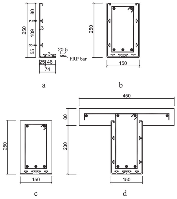
For the convenience of adjustment to the cross section size of beam, an L-shaped GFRP pultruded profile was first fabricated, then two L-shaped profiles were connected with GFRP bar to form a U-shaped profile. To ensure an efficient section, composite action between the GFRP permanent formwork and the concrete is essential. So the mechanical bond is provided with some T-up-stands on the GFRP internal surface which was covered with a curing epoxy mortar, as shown in Fig. (1).
2.2. Beam Specimens
Five rectangular beams and one T-beam were fabricated. All the beams were 2000mm long. The rectangular beams were 250mm in height and 150mm in width. The flange width and thickness of the T-beam were 450mm and 80mm, respectively. The height of the T-section was 310mm and the thickness of web was 150mm, as shown in Fig. (1).
The different configurations of tested beams are shown in Table 1, where beams FB1, FB2 and FB3 were RC beams combined with U-shaped GFRP profile, PB was control RC beam, RB1 was RC beam combined with GFRP only at the bottom of beam and TB was T-beam combined with U-shaped GFRP only around the web of beam.

| Beams | Cross section(mm) | Tension steel rebars | Stirrups | GFRP |
|---|---|---|---|---|
| FB1 | 150×250 | 3ϕ8 | ϕ8@ 60 | U-shaped |
| FB2 | 150×250 | 3ϕ12 | ϕ8@ 60 | U-shaped |
| FB3 | 150×250 | 2ϕ16 | ϕ8@ 60 | U-shaped |
| PB | 150×250 | 3ϕ12 | ϕ8@ 60 | No |
| RB1 | 150×250 | 3ϕ12 | ϕ8@ 60 | Only bottom |
| TB | bf×hf×b×h= 450×80×150×310 |
3ϕ12 | ϕ8@ 60 | U-shaped |
3. RESULTS AND DISCUSSIONS
3.1. The Moment-curvature Curves
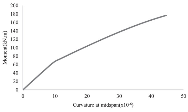
For the limitation of space, the moment-curvature curve of the tested beam TB is only shown in Fig. (2).

3.2. The Change Characteristics of Flexural Stiffness
From the moment-curvature curve shown in Fig. (2), it can be seen that both moment-curvature relation and flexural stiffness of hybrid beam change along with the increase of bending moment, and it can be divided into three stages:
(1) Stage I: It was stage I from the initial loading to the cracking of concrete in which the beam behaves elastically while the relationship between moment and curvature was nearly linearity.
(2) Stage II: It was stage II from the cracking of concrete to the yield of tensile steel. The moment-curvature curve appeared a turning. The curvature increased fast while the flexural stiffness decreased with the increase of bending moment.
(3) Stage III: It was stage III after the yield of tensile steel. The moment-curvature curve appeared a second turning. Flexural stiffness continued to decrease while the curvature increased further.
3.3. The Calculation of Flexural Stiffness
Based on tests and for the sake of simplicity the following basic assumptions are made in the derivation of short-term flexural stiffness for hybrid beams:
- Plane sections before bending remain plane after bending.
- The GFRP profile web's contribution to the flexural stiffness is ignored.
- The lower flange area of GFRP profile is converted to the tensile steels area according to the strength equivalent principle.
Based on the above assumptions, the derivation of short-term flexural stiffness for hybrid beam is shown as follows [10]:
-
Geometric relationship
According to the plane section assumption, the relationship between mean curvature and mean strain is:

(1) -
Physical relationship
The tensile steels in beams have not yet yielded in serviceability state, so the stress-strain relationship of steel is still nearly linearity. The elastic-plastic properties should be considered in the stress-strain relationship of concrete’s compression area. The physical relations can be expressed as:

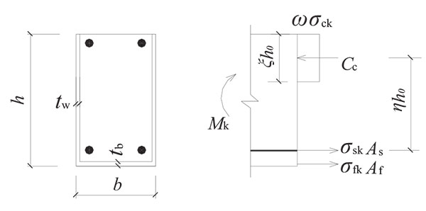
(2) - Equilibrium relationship For the cracked rectangular cross section, as shown in Fig. (3), the mean stress of equivalent rectangular stress block in the compressive area of concrete is ωσck, the compressive depth of section is ξh 0, and the internal lever arm from the resultant internal compressive force of concrete to tensile force of steel is ηh 0.
The lower flange area of GFRP profile is converted to the steel area according to the strength equivalent principle.
 |
(3) |

By equilibrium of forces at the cracked section we have:
 |
(4) |
From the above equations we have:
 |
(5) |
By the relationship between mean strain and cracked section strain, namely  and
and
 , combined with Eq.(2) and (5), the mean strain in tensile steel and extreme compressive fiber of concrete can be obtained by
 |
(6) |
 |
(7) |
Where,
 is a compound coefficient of mean strain in the extreme compressive fiber of concrete.
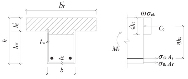
For T-section with compressive flange shown in Fig. (4), by equilibrium of forces we have:
 |
(8) |
Where,
 is the strengthen coefficient for compressive flange.

By using Eq.(1) and substituting Eq. (6) and Eq.(7) into the following Equation, we have:
 |
(9) |
By introducing αE = Es/Ec,
 , the expression for flexural stiffness Bs under bending moment Mk is:
 |
(10) |
According to the expression of short-term flexural stiffness for reinforced concrete beam provided by Code for Design of Concrete Structures (GB50010-2010), the expression of flexural stiffness for hybrid beams can be taken as:
 |
(11) |
 |
(12) |
Where: ψ — uneven coefficient of longitudinal tensile reinforcement strain between cracks: If ψ<0.2, take ψ=0.2; if ψ>0.2, take ψ=1.0.
ftk—characteristic value of tensile strength of concrete.
ρte—effective ratio of reinforcement.
σsk— tensile stress in steel under the short-term bending moment, which is calculated by Eq.(5).

η— internal lever arm factor of cracked section. Take η=0.87.
3.4. The Calculation of Midspan Deflections
All the hybrid beams were tested under three points loading, so the midspan deflections of which under short-term moment can be taken as follows:
 |
(13) |
Where, l is the span of tested beam. The expression of Bs is shown in Eq. (11).
The theoretical values of midspan deflections for hybrid beam can be calculated by using the above formula. The comparison between tested values and computed values is shown in Table 2. During serviceability state, the short-term moment Mk of hybrid beams was generally in stage II of moment-curvature curve, so Mk in Table 2 should be taken as the moment My when the steel yielded.
It can be seen from the Table 2 that the tested values agree quite well with the computed values.
CONCLUSION
In this paper, deferent types of reinforced concrete beams wrapped with GFRP pultruded profiles and a control RC beam are tested under three points loading. The moment-curvature curves of all tested beams are obtained. The change characteristics of flexural stiffness for tested beams are analyzed, and the short-term flexural stiffness formula is derived. The midspan deflections, which are calculated using flexural stiffness formula, agree quite well with the experimental values.
| Beams | My (kN.m) |
Bs(×1012) (N.mm2) |
Midspan deflection f(mm) | ||
|---|---|---|---|---|---|
| Experimental values | Calculated values | fyc/fyt | |||
| FB1 | 30.26 | 1.86 | 3.2 | 4.39 | 0.73 |
| FB2 | 55.60 | 2.24 | 6.3 | 6.70 | 0.94 |
| FB3 | 73.97 | 2.42 | 7.6 | 8.27 | 0.92 |
| PB | 29.73 | 1.83 | 4.5 | 4.38 | 1.03 |
| RB1 | 48.42 | 2.26 | 6.2 | 5.78 | 1.07 |
| TB | 89.12 | 4.93 | 4.6 | 4.88 | 0.94 |
CONSENT FOR PUBLICATION
Not applicable.
CONFLICT OF INTEREST
The authors confirm that this article content has no conflict of interest.
ACKNOWLEDGEMENTS
The study was funded by the National Natural Science Foundation of China (Project No. 50868004) and Natural Science Foundation of Hainan Province (Project No. 514209). The authors are thankful to the Department of Civil Engineering at TsinghuaUniversity for providing the necessary facilities for the experiments.


