All published articles of this journal are available on ScienceDirect.

Experimental Study on Shear Behavior of Mid-rise Assembled Monolithic Concrete Shear Walls with Varying Axial Compression Ratio
Abstract
Objective:
Quasi-static tests of three mid-rise assembled monolithic concrete shear walls, whose aspect ratio is 2.0, were completed in this paper. The failure mode of three new-type shear walls and the effect of axial compression ratio were studied.
Result and Conclusion:
The result showed that the brittle failure was extinct, and the new-type shear walls had good deformability whose ductility factors were over 4.3. The axial compression ratio had significant influence on the mechanical properties of the new-type shear walls. As the increscent of the axial compression ratio, the shear capacity and initial stiffness were improved, but the energy-dissipating capacity became worst.
1. INTRODUCTION
Assembled monolithic concrete shear wall structure, which is mainly site-assembled by precast or half-precast members subsequently partially pouring concrete in place, plays an important role in housing industrialization of China. It has virtues of rapid-speed construction, high-quality products, saving costs, etc. The key technology provides the reliable and convenient connection for each unit, which is the basis of popularizing the application of this wall structure.
Both experimental and theoretical studies on the connection are available in the literature. Rizkalla S H conducted a test on common horizontal joints applied in the precast shear wall panels, which demonstrated that the shear resistance of horizontal joints is determined by the shear frictional resistance between the precast wall panels and the performance of shear keys [1]. Six precast concrete shear walls having joint connecting beam were tested through quasi-static test by Dun Wang and Xilin Lu, etc. Test results show that the failure mode of precast concrete shear wall specimens is nearly the same as that of monolithic shear wall, and loads can be effectively transferred by the joint connecting beam [2]. Moreover, 4 pre-cast reinforced concrete shear wall specimens were tested under cyclic reversed loading by Jiaru Qian and Yuanyuan Peng, etc. The results show that the cast-in-site stripe can connect the pre-cast walls into a unit with the integrity behavior of the rough interface of the side face of pre-cast wall being better than that of the shear keys [3].
The basic unit of assembled monolithic concrete shear wall structure is the precast concrete slab which has cylindrical holes for vertical and rectangular holes for horizontal. They are connected by vertical and horizontal joints. The vertical joints consist of transverse reinforcement, cast-in-situ concrete and new-old concrete interface. Researches show that the assembled monolithic concrete shear wall exhibits a good seismic behavior avoiding the brittle shear failure [4-6]. Additionally, the construction for vertical joints is easily and the connection between different precast concrete slabs by vertical joints is reliable [7].
Axial compression ratio is a key parameter in the seismic design of shear wall, which has a great impact on walls’ shear behaviors. The researches on the axial compression ratio of the assembled monolithic shear walls always focused on the low-rise walls, but the researches on mid-rise walls [8] are sparse. In this paper, three assembled monolithic concrete shear walls with vertical joints were tested under reversed-cyclic lateral loading. Failure pattern, hysteretic behavior, and deformability were analyzed to investigate the influence of axial compression ratio on the walls’ shear behavior. Results of this experiment can be a basis for the application of this wall structure.
2. TEST SPECIMEN INFORMATION
The three test wall specimens, which consist of grade beam, wall section, and loading beam, are denoted by 2-DW5-L2, 2-DW10-LN1 and 2-DW12-LN2. The aspect ratio of them was 2.0, suggesting that the height from the upper surface of the grade beam to the lateral loading location was 3200mm. The rectangular section size of the shear wall was 1600mm×200mm, including the boundary element 200mm and the vertical joint 20mm.Taking the axial compression ratio as changing parameter in the test, the ratios of specimen 2-DW5-L2, 2-DW10-LN1 and 2-DW12-LN2 were 0.15, 0.10 and 0.25 respectively, and the corresponding axial loads were 1575kN, 1072kN and 2693kN, respectively.
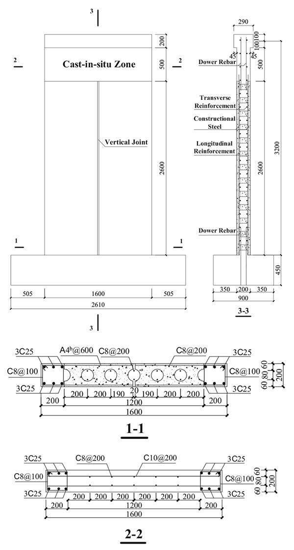
The dimensions and reinforcement details are depicted in Fig. (1). The shear capacity is larger than flexural capcity by design. The transverse reinforcements of the shear walls are placed in the horizontal holes rather than the slab, which can provide shear capacity. Meanwhile, the transverse reinforcements are important components of the vertical joint.
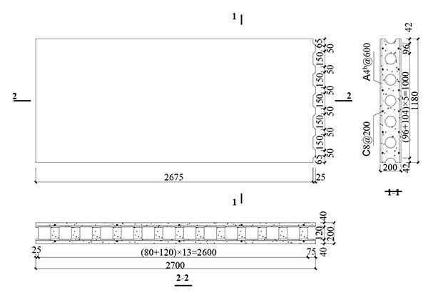
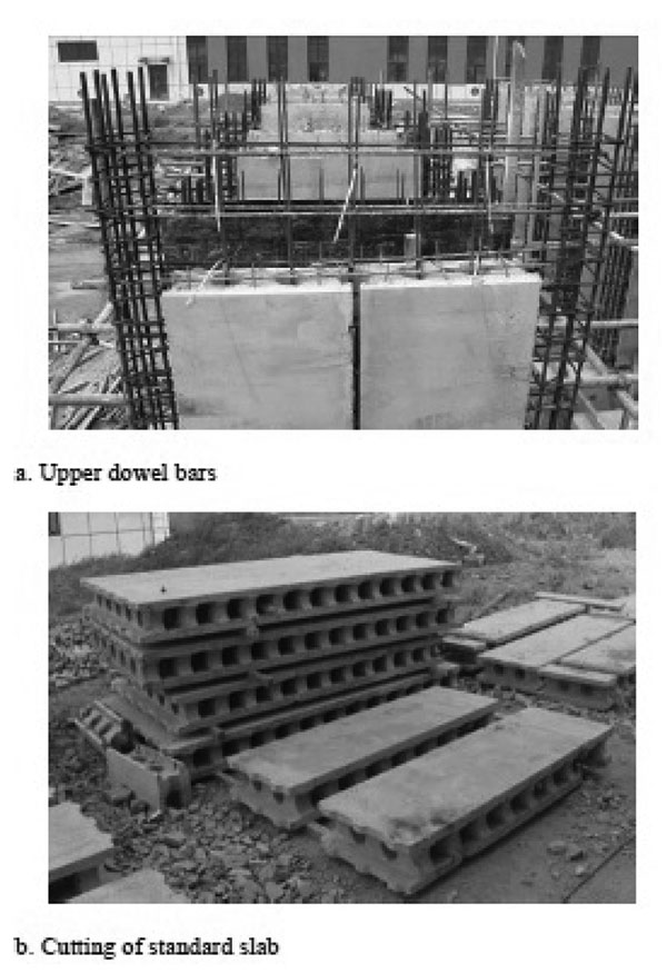
The precast concrete slab used in the assembled monolithic concrete shear walls is shown in Fig. (2). In order to ensure the connection between the shear wall and the grade beam, the keyway was designed at the bottom of then precast concrete slab, and the same purpose for the vertical dowel rebars inserted into each hole of 410mm (which were embedded into the foundation). The length of standard precast concrete slab was 2700mm, the width was 1180mm, and the thickness was 200mm. In order to achieve the designed aspect ratio 2.0, there was cast-in-sit concrete zone at the top of the shear wall whose height was 500mm (Fig. 3). The precast concrete with a height of 100mm chiseled off at the top of the precast concrete slab, and the vertical reinforcements stretched into the loading beam to ensure the connection between the loading beam and the shear wall. For fabricating the specimen, each precast concrete slab was cut along the longitudinal center into two slabs with the width-height of 590mm×2700mm, and a 20mm-wide gap was reserved between the two parts when they were assembled. The two slabs turned over and connected by vertical joint. Some other details are shown in Fig. (3).
3. MATERIALS
Six standard concrete test cubes were reserved while making both the specimens and the precast slabs to measure the compressive strength, and the curing conditions were the same with the specimens. The compressive strength of concrete, which is listed in Table 1, was measured on the day of testing.
Grades of 400 (fy = 400Mpa) hot-rolled ribbed steel bars were used in the walls. Measured yield strength and the ultimate strength of steel bars which are denoted by fy and fu are shown in Table 2, respectively.
| Test unit |
f1cu,m /MPa |
f2cu,m /MPa |
nt |
N /kN |
|---|---|---|---|---|
| 2-DW5-L2 | 41.4 | 44.2 | 0.15 | 1575 |
| 2-DW10-LN1 | 41.4 | 45.6 | 0.10 | 1072 |
| 2-DW12-LN2 | 49.7 | 41.2 | 0.25 | 2692 |
| Diameter | fy/Mpa | fu/Mpa | Type |
|---|---|---|---|
| 8 | 338 | 504 | Stirrup, dowel bar, longitudinal reinforcement |
| 10 | 356 | 542 | Transverse reinforcement |
| 25 | 447 | 601 | Bending reinforcement |
4. TYPICAL INSTRUMENTATION LAYOUTS
The force, displacement and strain of steel bars were measured in the test. Force transformers were adopted to measure the vertical and horizontal load. The layouts of linear variable differential transformers (LVDT) are shown in Fig. (4a). They are the same for all specimens. Displacement measuring items involved top lateral deformation, sliding and rotation of the foundation, etc. In addition, positions of longitudinal reinforcement inside the precast slabs and bilateral side of the vertical joint were predicted to form visible vertical cracks in the literature [7], so was the location between boundary element and precast wall section. Hence, LVDTs of MH1~MH6 and MV1~MV6 were employed to measure both the relative vertical and horizontal deformations at the vertical cracks.
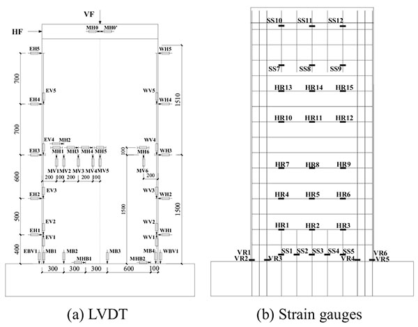
Strain gages were attached to the transverse reinforcement (HR1~HR15) and bending reinforcement in the wall boundaries (VR1~VR6), which are shown in Fig. (4b). In order to study the connection between the wall and rigid foundation, 5 strain gages were placed on the lower dowel bars. All the test data were analyzed by real time monitoring through DH3816 static strain measurement system on computer.
4.1. Loading Scheme
The axial load and horizontal load were applied by hydraulic jacks. The axial stress was applied prior to imposing lateral displacements, and it held constant throughout the test. The “Push” of horizontal hydraulic jack mounted to a reaction wall is regarded as the positive orientation. The horizontal load was controlled by the load-displacement system. Initially, it was controlled by the load magnitude with the differential of 200kN, and then by the displacement. After the appearance of the first diagonal crack, the differential was determined by the multiple displacement of this load cycle. Every control displacement was reversed twice until the specimen failed.
5. OBSERVED RESPONSE
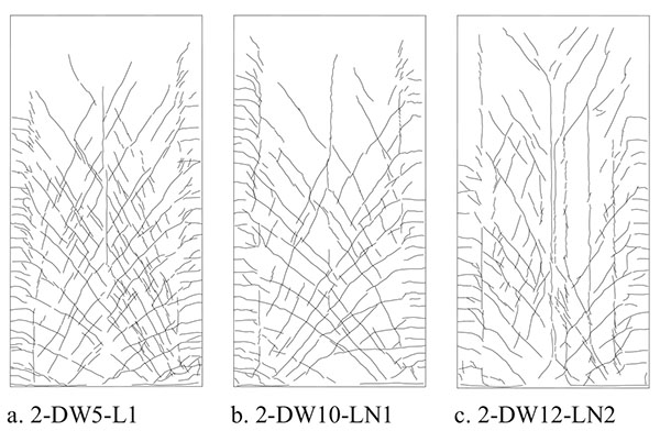
All the specimens exhibited a similar process of failure, which involved horizontal cracking of concrete at the bottom of the walls, oblique cracking at lower parts of the walls, slightly cracking at the vertical joints, and vertical cracking at the position between boundary elements and wall section, and the spalling of concrete. The walls failed in the bend-shear pattern, with tensile yielding of transverse reinforcement and longitudinal reinforcement in boundary elements.
The crack distribution is shown in Fig. (5). It can be drawn that the spacing of diagonal cracks decreased obviously with the increased axial compression ratio. Vertical compression cracks appeared at the local position of the walls when the axial compression ratio lifted to 0.25. The widths of the horizontal cracks at the bottom were 1.7mm, 2mm, and 1.5mm for 2-DW5-L2, 2-DW10-LN1, and 2-DW12-LN2 at the peak load, respectively, which indicates that the connection behavior of wall section and rigid foundation improved by lifting the axial compression ratio. The horizontal relative deformations at the vertical joints were 1.16mm, 0.16mm, and 2.0mm, at the same time, which indicated that the connection behavior of vertical joints weakened with the increased axial compression ratio.
6. RESULTS AND DISCUSSION
6.1. Hysteretic Curves and Skeleton Curves
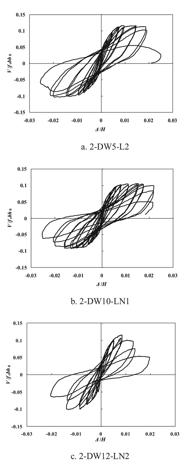
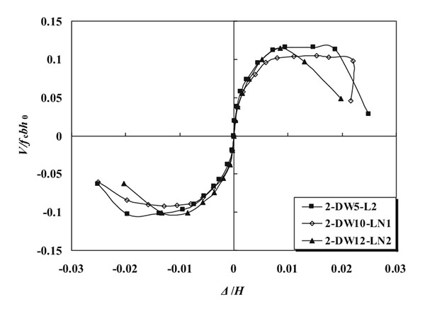
Hysteretic and skeleton curves specimens are given in Fig. (6 and 7), respectively. Where x axis of V/fcbh0 is the shear-compression ratio, and y axis of Δ/H is the drift ratio.
- Before the appearance of the first crack, the slopes of the hysteretic curves were approximately constant and the walls worked in the elastic range. With the progressing of the test, the diagonal cracks opened along their entire length and therefore, the resistance against relative deformation decreased when unloaded. The phenomenon of “pinching” was observed in the hysteretic loops.
- The “pinching” aggravated with the increased axial compression ratio.
- At the initial stage of the test, the skeleton curves of all the specimens nearly overlapped. The axial compression ratio had a little impact on the walls’ stiffness. With the increased ratio, the impact increased along with the walls’ stiffness.
6.2. Lateral Bearing Capacity and Ductility
Table 3 shows the lateral force and deformation of specimens at typical points, where θp and θu are the maximum drift and the ultimate drift, respectively. The nominal yield point was determined by method of geometric drawing [9], and the ultimate point was assumed to be where the peak load degraded to its 85% or at the end of the test. The coefficient of displacement ratio μΔ=Δu/Δy was calculated to assess the ductility of the walls, as shown in Table 3. For the results presented herein, the following can be drawn:
| Test Unit | Direction | Nominal yield point | Peak point | Ultimate point | μΔ | |||||||
|---|---|---|---|---|---|---|---|---|---|---|---|---|
| Fy /kN | Δy /mm | Fp /kN | Δp /mm | θp | Δu /mm | θu | ||||||
| 2-DW5-L2 | push | 721 | 741 | 12.52 | 10.02 | 1083 | 1148 | 62.70 | 1/60 | 69.47 | 1/48 | 6.63 |
| pull | 761 | 7.51 | 1213 | 46.99 | 63.27 | |||||||
| 2-DW10-LN1 | push | 604 | 677 | 7.82 | 8.74 | 970 | 1037 | 41.30 | 1/71 | 67.31 | 1/47 | 7.86 |
| pull | 751 | 9.65 | 1104 | 48.95 | 70.10 | |||||||
| 2-DW12-LN2 | push | 775 | 808 | 10.84 | 10.55 | 1090 | 1160 | 42.49 | 1/96 | 50.81 | 1/70 | 4.38 |
| pull | 841 | 10.26 | 1230 | 27.28 | 41.62 | |||||||
- Compared to 2-DW5-L2, the axial compression ratio of 2-DW10-LN1 decreased 33.3% and of 2-DW12-LN2, it increased 66.7%. The yielding load decreased 8.6% and increased 9.0% correspondingly. Lateral bearing capacity decreased about 9.6% when the axial compression ratio varied from 0.15 to 0.1, while increased about only 1% by lifting it to 0.25. Therefore, the lateral bearing capacity and yielding load improved effectively by increasing the axial compression ratio. While the magnitude exceeded to 0.15, the influence of axial compression ratio on the peak load and yielding load weakened.
- The ultimate drift ratios were all greater than 1/96 at the peak load, which exhibited good deformability and met the requirement of the current design code of China.
- The magnitudes of ductile coefficient were all greater than 4.3 and decreased with the increased axial compression ratio.
CONCLUSION
The following conclusions were drawn based on the study presented herein:
- All the specimens failed in the bending-shear mode, with the tensile yielding of longitudinal reinforcement in the wall boundaries and light crushing of concrete at the bottom the wall’s corners. Final damage of the walls was induced by the rhombic spalling of concrete in the compression zones.
- The lateral bearing capacity decreased with the axial compression ratio while did not increase the other way around. The ultimate drift ratios were all greater than 1%, which met requirement of the current design code.
- Diagonal cracks developed across the precast wall section and the cast-in-situ zone, meanwhile, dowel rebars in the upper part of the walls were in tension yet free from yielding throughout the duration of the tests. As a result, stress was effectivel transferred by the dowel rebars, which offered a reliable connection.
CONSENT FOR PUBLICATION
Not applicable.
CONFLICT OF INTEREST
The authors confirm that this article content has no conflict of interest.
ACKNOWLEGEMENTS
The authors would like to gratefully acknowledge the financial support provided by the National Science Foundation of China (Grant No. 51378450, 51508490) and the Project of Shandong Province Higher Educational Science and Technology Program (Grant No. J13LG09).

