All published articles of this journal are available on ScienceDirect.
Research on Base Isolation for Seismic Retrofitting of Adjacent Structures Connected with a Large Floor
Abstract
Introduction:
Seismic isolation has been proven to be an efficient approach to seismic retrofitting of structures based on the concept of reducing the seismic forces by lengthening the structural fundamental vibration period. However, superstructures may collide with each other under seismic excitation as the top displacement increases in the case of base-isolated adjacent structures. The relative displacement of top floors of superstructures is decreased more effectively by connecting the isolation layer of adjacent structures with a large floor, compared with the method to increase the width of seismic joint by using building monolithic movement technology. A specific engineering of base isolation for retrofitting of existing adjacent frame structures is studied in this paper.
Methods:
Seismic response was evaluated for the structures in different cases by time-history analysis. Parametric studies are performed in order to achieve the laws of top displacement difference of superstructures influenced by the change of dynamic characteristic of towers in the case of base-isolated multi-tower structure with a large floor.
Results and Conclusion:
The results of extensive numerical analysis verify the effectiveness of isolation with a large floor in minimizing the forces from earthquake and protecting the top story from crashing into each other, which has important reference value for application of retrofitting with isolation technology on adjacent reinforced concreted frames.
1. INTRODUCTION
Seismic isolation has been proven to be an efficient approach to earthquake resistant-design of structures based on the concept of reducing the seismic demand rather than increasing the seismic resistance capacity of the structure, and is one of the preferable alternatives in seismic retrofitting of historic structures without impairing their architectural characteristics [1]. Many examples of retrofitting existing buildings and bridges use base isolation to reduce the damage in the newer buildings to acceptable levels, in the event of a moderate to strong earthquake [2].
Nevertheless, the width of the provided seismic gap in most cases cannot be unlimited due to practical constraints, especially in cases of retrofitting existing structures. The retrofit option of using base isolation to detach the structure from the earthquake ground motions reduces the transmitted acceleration into the superstructure and amplifies the absolute displacement of structure which may beyond the distance of existing seismic joint. This may result in large relative motions between the towers, or may even lead to catastrophic collision. A part of an extensive research work concerning the numerical investigation of poundings of seismically isolated buildings with adjacent structures is presented by using a specially developed software application [3-5]. Researchers have investigated dynamic responses of two buildings connected by viscoelastic dampers under bidirectional excitations [6-9]. This paper elaborates a relatively new and cost effective scheme of connecting the ground floor of towers with a large floor to coordinate the relative displacement of the top floor of the building. Compared with using building monolithic movement technology to increase the separation gap distance, this method has the advantages of easy construction, short construction period and certain economic benefits [10]. The seismic behavior of the whole structure is not as good as that of a single structure. Under the earthquake, towers which vibrate severally if there is no connective structures occur interacting because of the connection. The responses are more complex than that of a single tower or twin towers without connective structures [11]. The specific objectives of the study are to demonstrate the usefulness of avoiding collision and damage by connecting the base into a whole plate in seismic isolation retrofitting of the structures.
2. ENGINEERING INFORMATION
The science buildings of a middle school using frame structure in Suqian city, Jiangsu province is studied in this paper. A total construction area of structures is 9470 m2 in plan (Fig. 1). The seismic fortification intensity of the structure is 8 degrees (0.30g) and the ground type is class III according to seismic ground motion parameter zonation map and the report of engineering geological exploration.
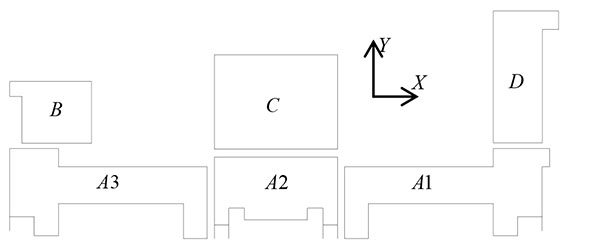
The basic building information of towers is shown in Table 1, including the construction areas, the story height of superstructures, the number of floors and the total height of the structures. As the seismic fortification criterion for the school buildings is increased according to the current Chinese code for seismic design of buildings, the existing reinforcing bars of structural components cannot meet the relevant requirements. Base-isolation had the effect of reducing the earthquake force demands on the superstructure to 30% of the demands for a fixed-base structure. It was feasible to design the superstructure to remain elastic with this force reduction. Through comprehensive comparisons of all the schemes, the method of base-isolated adjacent structures connected by a large floor is adopted in this project because the width of the seismic gap between A1 and A2 is 10cm less than the limitations of 40cm provided by the code for seismic design of buildings.
| Items | A1 | A2 | A3 | B | C | D |
|---|---|---|---|---|---|---|
| Construction area/m2 | 2731 | 2293 | 2731 | 462 | 595 | 580 |
| Typical height/m | 3.6 | 3.6 | 3.6 | 3.6 | 3.6 | 3.6 |
| Ground story height/m | 3.6 | 3.6 | 3.6 | 4.5 | 5 | 5 |
| Stories | 7 | 8 | 7 | 2 | 2 | 2 |
| Total height/m | 25.2 | 28.8 | 25.2 | 8.1 | 8.6 | 8.6 |
3. ISOLATION LAYER DESIGN
In this paper, an FEM analysis model of two structures elected from the buildings was established by ETABS with the seismic gap of 10 centimeters. The top plate of isolation layer was arranged on the foundation beams which connected by the bottom of columns in the ground floor. Two translational degrees of freedom of X and Y axis direction and torsional degree of freedom of adjacent structures were coupled. The behavior of the seismic isolation system is simulated using a bilinear inelastic model, which is a more representative and appropriate model. The bearings considered are isotropic with similar properties in two horizontal orthogonal directions. In the case of the LRB, the bilinear behavior is justified by the yielding of the lead core. The three parameters that determine the bilinear inelastic model are the yielding force (fy), the initial elastic stiffness (k1) and the post-yield stiffness (k2). For all performed simulations, in the frame of the currently presented work, the values of these parameters were empirically selected.
In order to guarantee the effect of vibration isolation reinforcement, the choices and the arrangements of the isolators should be researched. Within the same isolation layer, the vertical compressive stress and the shear deformation of the rubber isolation bearing should not exceed limit of category II frames under the excitation of the rare earthquake. Furthermore, torsional response of buildings excited by seismic action is an extremely complex problem, which cannot be avoided because of the accidental eccentricity and the irregularity of structure. The building is quite rigid in comparison to the isolation system, structural torsional deformations are considered to be focused on the isolation layer. The existing research results show that the story shear force will be amplified by the torsional effect due to the irrational arrangement of isolators, counteracting the reduction of forces by seismic isolation. Unrecoverable deformations in the rubber isolators may be caused by the tensile stress because of torsional movement under the severe earthquake, which even leads to the structure collapsed. Isolation layer design should strengthen the anti-torsion capacity of the whole structure and assure the elimination of torsional ingredient in the dynamic response to reduce interlayer shear force effectively and the following theoretical derivation and numerical model without regards to the torsional effect are based on the assumptions above. Eventually, the isolation system consists of 7 laminated lead-rubber bearing and 20 laminated rubber bearings, one at the base of each column.
In this paper, the whole structure combined with two adjacent structures differing in the somatotype has a bigger eccentricity at longitudinal direction. It is difficult to avoid the torsional responses when the whole structure vibrates at the Y direction. In order to diminish earthquake torsion effect of the superstructure largely and realize the optimization design, the stiffness center of isolator layer should coincide with the mass center of the whole building as much as possible. The first three vibration modes of the whole structure are shown in Table 2:
| Mode |
Period (s) |
Participating mass | ||
|---|---|---|---|---|
| Translation X | Translation Y | Torsion | ||
| 1 | 2.398 | 0.11 | 98.97 | 0.58 |
| 2 | 2.374 | 99.65 | 0.11 | 0..00 |
| 3 | 2.234 | 0.00 | 0.59 | 98.94 |
4. PARAMETRIC STUDY OF NUMEICIAL MODEL
4.1. Numerical Model and Equations of Motion
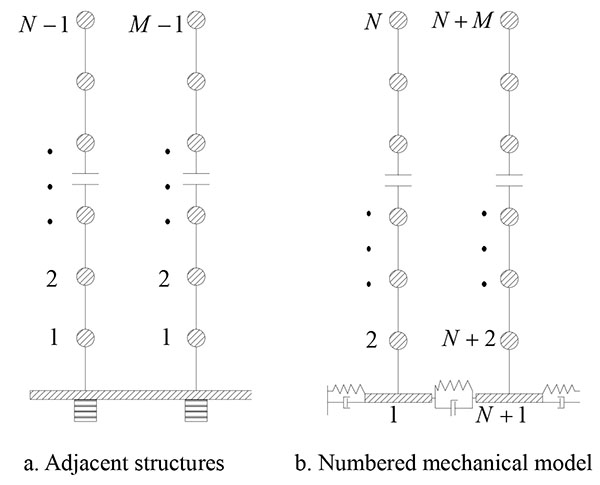
The two adjacent structures are assumed to be symmetric with their symmetric planes in alignment. The ground motion is assumed to occur in one direction in the symmetric planes of the buildings so that the problem can be simplified as a one-dimensional problem as shown in Fig. (2) schematically. Both structures are assumed to be subjected to the same ground acceleration.
Fig. (2a) illustrates a structural multi-degree-of- freedom (MDF) elastic system consisting of two adjacent frame structures of N-1 and M-1 (N≥M) stories, connected by a large ground floor. The DOFs of simplified numerical model of two adjacent buildings including the large floor are numbered as Fig. (2b): a taller building on the left and a shorter building on the right. Equations of motion of a single structure exclusive of torsional responses can be expressed as Eq.(1):
 |
(1) |
where KI, KII and CI, CII are the stiffness and the damping matrixes of the single structure based on story shear model; NI(t) and NII(t) are N-dimensional and M-dimensional column vectors with N-1 and M-1 zero elements and the last nonzero element representing a pair of interaction force.
If the degrees of freedom (DOFs) of each structure are numbered upwards starting from the first floor level as Fig. (2), the corresponding mass and stiffness matrixes can be aggregated as Eqs.(3)-(5). The equation of motion of the coupled structural system subjected to seismic excitation at X direction can be expressed as Eq.(2):
 |
(2) |
 |
(3) |
 |
(4) |
 |
(5) |
where the mass matrix of the superstructure is a diagonal matrix and characterized by the mass of each floor; kb and cb are the stiffness and the damping coefficients of the large floor junction; x(t) is the n-dimensional story drift vector; n equals to the sum of M and N.
To verify the effectiveness of the scheme as a new promising alternative for seismic retrofitting of adjacent structures, reduction of two main response quantities, namely, the story shear force and the absolute displacement differences of top floors, is the main concern. The effectiveness of this technology, however, depends heavily on the type of connective devices, on the structural properties of the neighboring buildings and on the response quantity of interest. In judging the contribution of a natural mode to the dynamic displacement responses of top floors, it is necessary to consider the combined effects of the modal contribution factor and the dynamic response factor [12]. The dynamic response factor of modes is determined by predominant frequency of different earthquake waves and the frequency of modes. The general law of the dynamic response factor is that the displacement of single-degree-of-freedom (SDF) systems decreases with the higher frequency of corresponding mode according to elastic displacement spectra method. The present study focuses on the law of the modal contribution factor with the changes of dynamic characteristics of superstructure and stiffness of isolation layer. It will be interesting to study the changes of dynamic characteristic of flexible multi-story adjacent structures supported on isolation systems with an unsuspected stiffness which has a big impact on the response of the superstructure. The relative displacement of ith mass of MDF elastic systems excited by ground acceleration üg(t) can be expressed as Eq.(6) on the basis of mode superposition method [13].
 |
(6) |
whereγj is a modal participation factor of jth mode which can be expressed as Eq.(7); Xj is the ith natural mode vector of the system without damping calculated by the mass and stiffness matrix aggregated above; ∆j(t) is the elastic displacement of the equivalent SDF system with damping ratio ζj and natural frequency ωj defined in Eq.(8) .
 |
(7) |
 |
(8) |
As shown from the Fig. (3), the superstructures arranged with the same direction of vibration are more unlikely to collide with each other if the modal contribution factors of first and third modes occupy a more leading position based on the mode superposition method. The sum of the modal contribution factors over all modes is unity. So in this paper fi defined by Eq.(9) is called the ratio of modal contribution factors of higher modes to the first and the third modes, implying that it is a measure of the degree to which the expected modes participates in dynamic displacement responses:
 |
(9) |
 |
(10) |
where r1i and r3i expressed as Eq.(10) are the modal contribution factors of first and third mode at DOF i corresponding to the floors which most likely collide with each other. By the rule of numbering above, the Mth and nth DOF should be the main targets to research because the corresponding floors of two adjacent structures collide with each other most possibly. According to the laws of fi varying with the different dynamic characteristics of structures, an overall assessment of the properties of superstructure can be conducted to inspect whether the method of isolation with a large floor is applicable to the existing adjacent building.
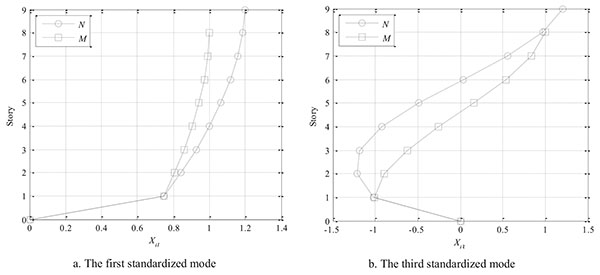
To delineate the modal contribution factors of isolated structure with a large floor, a comprehensive parameter study taken crucial factors into consideration is highly necessary. Ordinary buildings generally adopt regular structure arrangement, of which each layer has the same size of section because of the similar building function. Chinese code for seismic design of buildings [14] requires that elastic drift angle of story should be limited with a certain range in order to prevent structure from collapsing under severe earthquake due to too large elastic-plastic interstory drift of weak layer. The shear stiffness and the mass of each story are identical the same, when the structure is designed in strict accordance with the standard design codes. The variable ratiom is given to describe the differences of the floor mass of two structures as Eq.(11):
 |
(11) |
where the m1i and m2i represent the constant floor mass of the adjacent structures.
The variable η is defined as stiffness ratio factor to describe the differences of the stiffness of two structures in Eq.(12):
 |
(12) |
where the k2i and k1i represent the constant elastic stiffness of the adjacent structures. Hence, the variable ratiom and η depicted the different dynamic characteristics of superstructures. It is seen that the displacement differences of top floors are influenced by the changes of ratiom and η. For a more accurate assessment of the whole structure, the third variable ratiok influencing on the performances of the whole structures is defined as the ratio of stiffness of isolation layer to the stiffness of the superstructure which can be expressed as Eq.(13).
 |
(13) |
where ki is the stiffness of single rubber bearing. Following assumptions are made for the structural system under consideration:
- The dynamic response of the superstructure is only translational displacement subjected to single horizontal component of earthquake ground motion, while torsional responses are not considered for the system because the isolation design make the coordinate of center-of-mass and center-of-stiffness coincide.
- The superstructure is considered to remain within the elastic limit during the earthquake excitation because of the seismic isolation technology.
- The floors of each building are at the same level and have the constant mass and stiffness along the height of structure which is designed in strict accordance with the standard design codes.
4.2. Double-towers With Equal Elevations
Twin towers with equal elevations which have identical number of DOFs have been widely used in practical engineering. For the perfectly symmetrical adjacent structures with the same structural component arrangement and mass distribution, the dynamic response of the twin towers with a large floor is extremely close to the single structure. The scheme of seismic base-isolation using a large floor can effectively avoid the collision due to the accident eccentricity of mass and load caused by the construction quality.
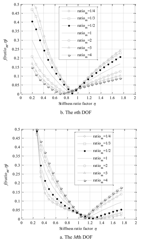
For the double-towers with an equal height which have differences on the dynamic characteristics, it is necessary to give the parameter variable of structure and assessment criteria which is convenient for the actual engineering design to judge the feasibility of base-isolation with a large ground floor. Parametric studies of ratiom and η are conducted to find appropriate value in order to achieve the minimum the ratio of modal contribution factor fM and fM+N of the adjacent structures. Effects on dynamic response mitigation of the 9-story adjacent structures are sought for different dynamic characteristics of superstructure. Assuming that N and M values are 9, the lateral stiffness of isolation layer is 1/10 of superstructure.
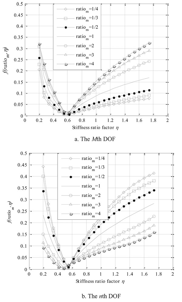
Fig. (4) shows that the variations of fM and fM+N change with the ratiom and η, meaning the relative contribution of first and third modes to response quantity of the whole structure subjected to ground motions. From Fig. (4), it can be observed that η should be kept from 0.9 to 1.1 for the purpose of guaranteeing fM and fM+N below 5%. The ratiom has relatively little influence on the f when η is in the optimum interval making the f inferior to 5%. When η exceeds 1.2 or decreases from 0.9, it is also observed that f increases with the increase of ratiom of the adjacent structure. The effects of the increasing f are severe for the flexible buildings, because superstructures are more possible to collide with the increasing ingredient of opposite motion under the earthquake. Furthermore, the adjacent structures with different ratiom have the same f when the η equals 1. Obviously, the designers of structures should pay more attention to the stiffness of the towers to judge whether the existing adjacent structures have a proportional stiffness to the mass.
4.3. Double-towers With Unequal Elevations
There must be different characteristics among adjacent structures with an unequal height due to different number of DOFs. Assuming that N and M values are 9 and 7, the lateral stiffness of isolation layer is 1/10 of superstructure. Consider the impact of the changes of ratiom and η on the ratio of modal contribution factors as in the above case.
As shown from Fig. (5), the general tendency of the function reveals that the performance of adjacent structures will deteriorate gradually when η decreases or increases from 0.75. The shorter building has a greater stiffness of the structure despite the proportional story stiffness and mass to the taller building. Hence, the story stiffness had better multiplied a reduction factor η less than 1 to bring f below 5%. The function shape of adjacent structures with an unequal height translates to the left to a certain extent with respect to those with an equal height. To facilitate implementation of actual engineering and get more general results, it is found that η has the same optimum range on condition that the number of the floors of superstructures with different height is in proportion from the enormous calculated datum. For example, when the N and M equal to 17 and 13, 9 and 7 or 5 and 4, the structures have the similar dynamic characteristics. Due to the limited applicability of base isolation for seismic retrofitting of structures by structure height, the following table gives the optimum range of η when variable N equals 9 and M changes from 4 to 9. Table 3 displays the assessment criteria of dynamic characteristics of common adjacent structures with the constant ratiof which is defined as the ratio of number of storeys of shorter building and taller buildings.
| N | M | ratiof | M | M+N |
Optimum η |
|---|---|---|---|---|---|
| 9 | 4 | 0.375 | 0.12-0.2 | 0.14-0.18 | 0.14-0.18 |
| 9 | 5 | 0.500 | 0.22-0.3 | 0.24-0.30 | 0.24-0.3 |
| 9 | 6 | 0.625 | 0.32-0.5 | 0.35-0.45 | 0.35-0.45 |
| 9 | 7 | 0.750 | 0.52-0.7 | 0.48-0.62 | 0.52-0.62 |
| 9 | 8 | 0.875 | 0.7-0.92 | 0.63-0.82 | 0.7-0.82 |
| 9 | 9 | 1.000 | 0.95-1.2 | 0.80-1.05 | 0.95-1.05 |
4.4. Influence of the Stiffness of Isolation Layer
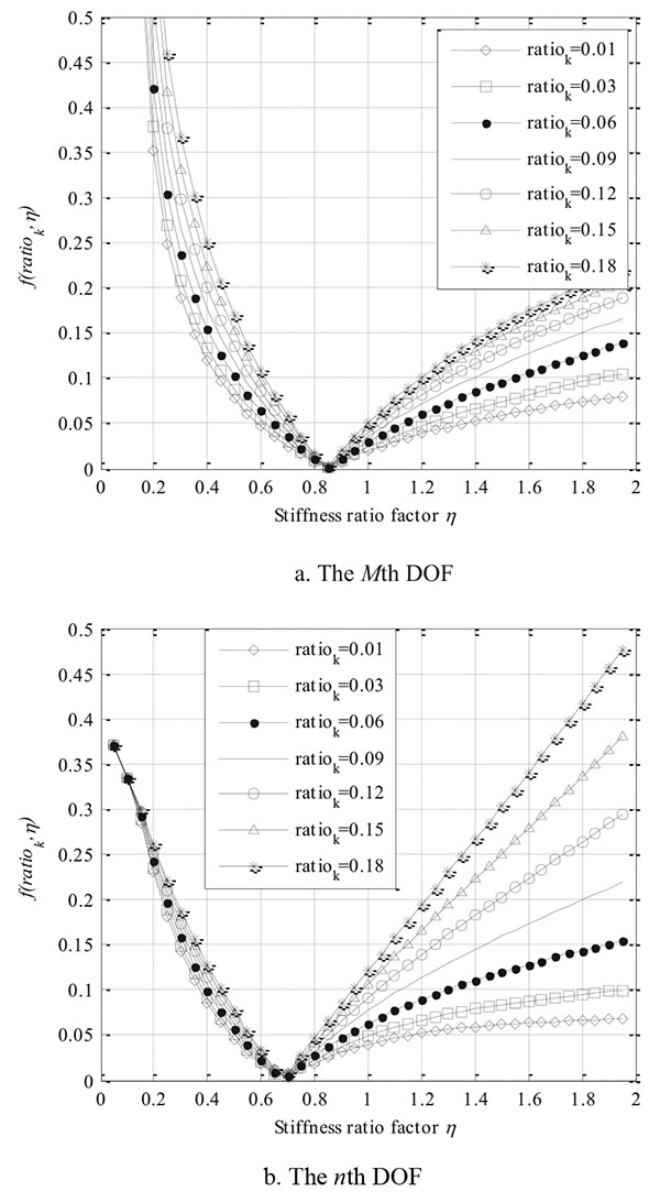
Isolation layer of structures retrofitted using base isolation devices is equivalent to the soft story of the corresponding conventional structure without any retrofit measures. There is a stiffness mutation of structures, since the building is quite rigid in comparison to the isolation system. The stiffness of the isolation layer is also an important parameter to guarantee that the response of the base-isolated adjacent structures meets its basic requirements regulated by design codes. It will be significant to study the dynamic behavior of flexible multi-story frame structure influenced by the parameter of ratiok. It is assumed that N and M equal to 9 and 8, the ratiom equals to 1.2 on the basis of the actual engineering mentioned above.
According to Fig. (6), there was a marked drop of f with the increase of η when η is less than 0.7 no matter what ratiok is. Since then, it grew in a straight line. The smaller ratiok is, the bigger the optimum range of f is. Negative influence brought by too large η of the adjacent structures could be minimized by reducing ratiok. It would be helpful for the application of the scheme in coupling structure control strategies.
5. TIME-HISTORY ANALYSIS RESULT
The methodology described above is tested through an 8-story building and a 7-story building coupled with enlarged base at the ground floor. In order to reduce the torsional response of coupled buildings about the vertical axis through the center of mass, the location of the isolators were adjusted to make the ordinates of center-of-stiffness and center-of-mass coincide as much as possible according to the information of the structure calculated by ETABS program. The information of the floor masses and story stiffness of the two buildings is given in Table 4:
| Story | A2 | A1 | ratiom | η | ||
|---|---|---|---|---|---|---|
|
stiffness (106kN/m) |
mass (t) |
stiffness (106kN/m) |
mass (t) |
|||
| 8 | 0.333 | 462 | ||||
| 7 | 2.124 | 577 | 2.760 | 586 | 1.02 | 1.28 |
| 6 | 2.124 | 538 | 3.272 | 661 | 1.23 | 1.25 |
| 5 | 2.124 | 538 | 3.272 | 663 | 1.23 | 1.25 |
| 4 | 2.124 | 545 | 3.272 | 663 | 1.22 | 1.27 |
| 3 | 2.124 | 538 | 3.272 | 663 | 1.23 | 1.25 |
| 2 | 2.124 | 538 | 3.272 | 663 | 1.23 | 1.25 |
| 1 | 2.124 | 538 | 3.272 | 674 | 1.25 | 1.23 |
| 0 | 0.033 | 369 | 0.039 | 400 | 1.09 | 1.30 |
Table 4 shows that the floor mass and story stiffness are distributed uniformly along the height of structures. The ratio of floor mass of A1 to the floor mass of A2 is nearly 1.2. According to the analysis above, the optimum range of η should be 0.7~0.82 because the taller building has 8 stories and the shorter one has 7 stories. The actual stiffness ratio η is 1.26, which means the higher influence of high-order vibration modes on the superstructure. It is necessary to consider reducing the isolation layer stiffness to control fM and fM+N within a certain range. fM and fM+N of the practical structure is less than 5% calculated by substituting the mass and the stiffness of floors including the isolation layer in the program by MATLAB, proving that the dynamic properties of adjacent structures are suited for the method. For the base-isolated adjacent building, the response quantities of interest are the superstructure absolute displacement differences and the story shear force.
5.1. Story Shear Force
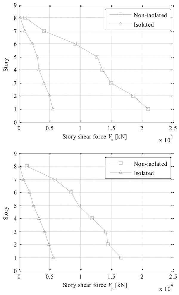
In this section, extensive time history response analysis was carried out to confirm the control performance of the scheme for example structures subjected to various ground motions. Fig. (7) compares the base shear force results of the original structure and the retrofitted structure with a large ground floor excited by Northridge earthquake record in X and Y directions. The figure indicates that there is significant reduction in the story shear force of the superstructures retrofitted by the base-isolation technology with respect to the conventional structure. This implies that the base isolation is effective in retrofitting the existing buildings.
5.2. The Displacement Difference of Top Floor
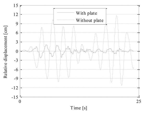
Relative displacement differences at potential pounding floor (the seventh floor in this paper) of building A1 and A2 should be evaluated under intense earthquake to verify whether the provision of separation gap distance can avoid collision of the two adjacent structures. Fig. (8) shows the time-history curves of the relative displacement of the potential pounding location of the retrofitted structures with and without a large ground floor excited by Northridge earthquake record in X direction. The amplitude of acceleration record was scaled to 510 gal. The peak relative displacement difference of top floor is 12cm if the structures isolated without large floor, which can result in a collision of the two adjacent structures. And the relative displacement of target floor is reduced to 2.5cm with the plate, implying that the scheme of connecting the ground floor of towers with a large floor can reduce the relative displacement effectively.
CONCLUSION
The scheme of base-isolation reduces the story shear force in the superstructure, in contrast to conventionally designed structures suffering severe damage during strong earthquakes. Both the relative displacement and acceleration response of are decreased to the accepted degree. It is cost effective to arrange the isolators under the big floor in order to accommodate such large relative displacements to the ground during strong earthquake excitations, when the width of the provided seismic gap in most cases cannot be unlimited due to practical constraints, especially in cases of retrofitting existing structures. Extensive sensitivity of various important structural parameters of both isolator and superstructure to find the influence on the behavior of adjacent structures isolated with a large ground floor are studied in this study. The important design parameters include the ratio of mass and the coefficient of stiffness ratio of the superstructure and the ratio of stiffness of isolation layer to the superstructure. The parametric study is not exhaustive, but from the trend of the results, the following conclusions may be drawn:
In order to avoid the collision of the adjacent structures of different dynamic characteristics under the earthquake, it is necessary to ensure the uniformly vibration of twin towers to reduce the relative displacement by judging whether the structural parameters are in optimum range. If the dynamic property of existing structures cannot satisfy the meet the requirements, it is necessary to adjust the stiffness of the isolation layer or adopt other measures to strengthen the security reliability of the structure to prevent adjacent structures from colliding with each other under seismic action.
CONSENT FOR PUBLICATION
Not applicable.
CONFLICT OF INTEREST
The authors confirm that this article content has no conflict of interest.
ACKNOWLEDGEMENTS
The authors acknowledge the support of the Young Scientists Fund of National Science Foundation of China (Grant No. 51008078) and the Research and Development Joint Center of Isolation Technology by Southeast University and Haida Corporation to develop the presented paper. Also, the authors thank the reviewers for their comments and suggestions which helped to improve this paper.


