All published articles of this journal are available on ScienceDirect.

An Integral Equation Model for a Pile in a Layered Transversely Isotropic Saturated Soil
Abstract
Objective:
In this paper, an integral equation model is established to predict the time-dependent response of a vertically loaded pile embedded in a layered Transversely Isotropic Saturated Soil (TISS).
Methods:
Based on the fictitious pile method, the pile-soil system is decomposed into an extended saturated half-space and a fictitious pile. The extended half-space is treated as a layered TISS, while the fictitious pile is considered as a 1D bar. The pile-soil compatibility is accomplished by requiring that the axial strain of the fictitious pile be equal to the vertical strain of the extended layered TISS along the axis of the pile. The second kind Fredholm integral equation of the pile is then derived by using the aforementioned compatibility condition and the fundamental solution of the layered TISS, which is equivalent to the solution of the layered TISS subjected to a uniformly-distributed load acting vertically over a circular area with the radius equal to that of the pile. The fundamental solution of the layered TISS is obtained via the Reflection-Transmission Matrix (RTM) method for the layered TISS. Applying the Laplace transform to the Fredholm integral equation, and solving the resulting integral equation, the transformed solution is obtained. The time domain solution of the pile-soil system is retrieved via the inverse Laplace transform.
Results and Conclusion:
Numerical results of this paper agree with existing solutions very well, validating the proposed pile-soil interaction model. A parametric study is carried out to examine the influence of some parameters on the response of the pile-soil system.
1. INTRODUCTION
Real saturated soils encountered in civil engineering are usually stratified and the properties of different layers may thus be different. Further, although most saturated soils are isotropic in the horizontal plane, due to the deposition process, moduli and permeability of the soil in the horizontal direction are usually different from those in the vertical direction considerably. Thus, it is reasonable to treat the soil as a transversely isotropic saturated medium. As piles are the most widely used foundation type in the world, it is thus important to investigate the interaction between the piles and the layered Transversely Isotropic Saturated Soil (TISS).
So far a number of methods have been presented for the investigation of the pile-soil interaction, which include load transfer method [1-3], finite layer approach [4-6], finite element method [7-9], boundary element method [10-13], “hybrid” type of approach [14-16], the fictitious pile method [17-22] and some other simplified analytical approaches [23-25].
To account for the influence of the pore pressure on the pile-soil interaction, Niumpradit & Karadushi [21] used the Biot’s theory and the fictitious pile method due to Muki & Sternberg [19, 20] to deal with the interaction between a pile and a saturated homogeneous half-space. However, they only obtained the final and initial state solutions. Apirathvoraku & Karasudhi [22] employed the same fictitious pile method to study the response of a single pile embedded in a saturated homogeneous half-space and subjected to a lateral force or a moment at the pile top. As noted above, due to the stratification of the real soil, piles are rarely installed in the ideal homogenous soil. To account for the stratification of the realistic soil, Senjuntichai [26] studied the time-dependent response of an axially loaded bar in a multilayered poroelastic half-space by the influence function of the multilayered poroelastic half-space and the Laplace transform method. Modeling the pile with the finite element method and using the soil’s fundamental solution obtained via the analytical layer-element method, Ai et al. [9] also provided a time-dependent solution for a pile embedded in a multilayered saturated soil.
As mentioned above, apart from stratification property, in engineering practice, the soil might exhibit transverse isotropy property [27, 28]. However, researches about the interaction between the pile and TISS have not been reported in the literature so far. Existing relevant researches are all concerned with the interaction between the pile and single phase transversely isotropic soil. For example, by treating the transversely isotropic soil with a combination of the order reduction approach and the integral transform method, Ai & Yi [13] presented a boundary element method solution for a single pile embedded in a multilayered transversely isotropic soil. Later, Ai [29] investigated the behavior of piles in a multilayered transversely isotropic soil subjected to vertical and horizontal loads simultaneously.
The main objective of this paper is to develop a model which can be used to predict the time-dependent behavior of a vertically loaded pile embedded in a layered TISS. To establish the model, the pile-soil system is decomposed into an extended saturated half-space and a fictitious pile according to the fictitious pile method first. The extended half-space is treated as a layered TISS, while the fictitious pile is as a 1D bar. The compatibility between the extended saturated half-space and the fictitious pile is accomplished by requiring that the vertical strain of the extended layered TISS along the axis of the pile is equal to the axial strain of the fictitious pile. The second kind Fredholm integral equation of the pile is then derived by using the aforementioned compatibility condition and the fundamental solution of the layered TISS. The fundamental solution of the layered TISS is obtained via the reflection-transmission matrix (RTM) method for the layered TISS. Applying the Laplace transform to the integral equation of the pile, and solving the resulting integral equation, the transformed solution is obtained. The time domain solution of the pile-soil system can be retrieved via the inverse Laplace transform. Numerical results obtained by the proposed model are compared with existing results. Then, a parametric study is presented to examine the influence of some soil parameters on the behavior of the vertically loaded pile in the layered TISS.
2. GOVERNING EQUATIONS AND THE FUNDAMENTAL SOLUTION FOR THE LAYERED TRANSVERSELY ISOTROPIC SATURATED SOIL
As mentioned earlier, to establish the integral equation for the pile embedded in the layered TISS requires the corresponding fundamental solution. Therefore, in this section, the governing equations of the TISS will be presented and the fundamental solution for the layered TISS will be introduced.
In the cylindrical coordinate system, the equilibrium equations of the TISS under the axisymmetric condition are as follows in Eq. (1)
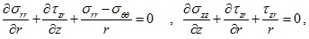 |
(1) |
where σ22, σrr, σθθ are the component of the total normal stress; σ2r is the total shear stress component. For the saturated soil, the effective stress principle can be represented as follows (Eq. 2):
 |
(2) |
in which
 denotes the total stress, the effective stress, and the pore water pressure vectors, respectively. For the TISS, the constitutive relations for the effective stresses have the following expressions (Eq. 3):
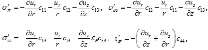 |
(3) |
where ur and uz are the displacement components in r and z directions, respectively. The parameters c11 - c44 in equation (3) denote the elastic constants of the TISS and they can be expressed as follows (Eq. 4):
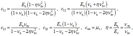 |
(4) |
where Eh, Ev and µv are the horizontal elastic modulus, the vertical elastic modulus and the vertical direction shear modulus of the soil, respectively; vh is the Poisson's ratio of the soil in the horizontal direction; vhv is the Poisson's ratio describing the horizontal strain caused by the vertical stress; vvh is the Poisson's ratio describing the vertical strain caused by horizontal stress and η is the ratio of the horizontal elastic modulus to the vertical elastic modulus of the soil.
As noted above, to establish the integral equation for the vertically loaded pile embedded in the layered TISS requires the fundamental solution for the layered TISS. The fundamental solution corresponds to the response of the layered TISS subjected to a unit vertical load uniformly distributed over a circular area in the extended layered TISS. The circular area is equivalent to the cross-section area of the pile. The layered TISS will undergo an axisymmetric consolidation when subjected to the circular uniform distributed load. With the RTM method, the aforementioned fundamental solution of the layered TISS can be obtained. Note that the fundamental solution is first obtained in the transformed domain with the use of the Hankel-Laplace transform. By means of the inverse Hankel-Laplace transform, the fundamental solution in the spatial and temporal domain can be retrieved. More details on deriving the fundamental solution for the layered TISS via the RTM method can be found in [30].
3. FREDHOLM INTEGRAL EQUATION FOR THE PILE EMBEDDED IN A LAYERED TISS
In this section, based on the fundamental solution introduced in the previous section together with the fictitious pile method due to Muki & Sternberg [19, 20], the second kind of Fredholm integral equations for the pile embedded in the layered TISS will be derived. As noted above, the fundamental solution is obtained via the RTM method [30].
3.1. Establishment of the Fredholm Integral Equation for the Pile
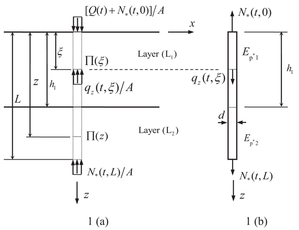
In this section, the pile subjected to a static vertical load embedded in a two-layered TISS is used as an example to show the procedure to establish the integral equation for the pile (Fig. 1). The integral equation for the pile embedded in the layered TISS with arbitrary layers can also be established by following the same procedure. Following Muki’s fictitious pile method, the pile-soil system is decomposed into an extended layered half-space TISS and a fictitious pile as shown in Fig. (1). As noted above, the extended layered TISS is treated as a three-dimensional continuum medium, while the fictitious pile is as a one-dimensional bar. The radius and length of the pile are assumed to be R and L, respectively. According to the fictitious pile method, the Young’s modulus of the fictitious pile can be obtained by subtracting the elastic modulus of the soil from the elastic modulus of the real pile, namely (Eq. 5)
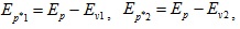 |
(5) |
where Ep*1 and Ep*2 are the Young’s moduli of the segments of the fictitious pile corresponding to the segments of the real pile embedded in the first and second layers, respectively; Ep is the elastic modulus of the real pile; Ev1 and Ev2 the vertical Young’s moduli of the first and second soil layers, respectively.
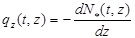
As shown in Fig. (1), it is assumed that the pile is subjected to an external load at the top. The axial force of the fictitious pile at time is N* (t,z); the vertical distributed load along the fictitious pile at time is qz(t, z); and the top and bottom of the fictitious pile are subjected to the forces N* (t, L) and at time, t, respectively (Eq. 6). The layered TISS is subjected to the reaction force qz (t, z) from the fictitious pile which is distributed over
 uniformly, where
denotes the circular area corresponding to the cross-section area of the pile with the vertical coordinate z and
uniformly, where
denotes the circular area corresponding to the cross-section area of the pile with the vertical coordinate z and
 as well as N* (t, L) distributed over
 and
and
 uniformly, respectively. According to the equilibrium condition for the fictitious pile, the vertical distributed load along the fictitious pile and the axial force of the fictitious pile at time t have the following relation:
 |
(6) |
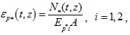
According to the aforementioned Muki’s fictitious pile method, to accomplish the compatibility between the pile and soil, the axial strain of the fictitious pile is assumed to be equal to the vertical strain of the extended layered TISS along the z axis, namely (Eq. 7)
 |
(7) |
in which
 represents the vertical strain of the extended TISS half-space at the center of the cross-section
at the time t and
represents the vertical strain of the extended TISS half-space at the center of the cross-section
at the time t and
 represents the axial strain of the fictitious pile at the coordinate z and the time t. The axial strain of the fictitious pile at the coordinate z is as follows (Eq. 8):
 |
(8) |
in which A represents the cross-section area of the pile.
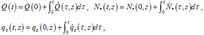
In this study, for generality, the external load acting at the pile top is assumed to be time dependent. Also, during the consolidation process, the axial force of the fictitious pile and the vertical distributed load along the fictitious pile are time dependent. Hence, the external load, the axial force and the vertical distributed load acting on the fictitious pile can be represented by (Eq. 9):
 |
(9) |
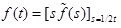
where the variable with a dot denotes the corresponding time derivative of the variable. Further, for the convenience of the subsequent presentation, the convolution between two arbitrary functions is defined as follows (Eq. 10):
 |
(10) |
in which f (t) and g (t) are two arbitrary functions.
In view of the forces acting in the extended layered TISS, and with the fundamental solution for the layered TISS, the vertical strain of the extended layered TISS at the center of
can be expressed as follows (Eq. 11):
 |
(11) |
in which N* (t, 0) and N* (t,L) represents the reaction forces acting in the layered TISS corresponding to the forces acting at the top and bottom of the fictitious pile at time t;
 is the fundamental solution of the vertical strain for the layered TISS, which denotes the vertical strain at time t and at the center of
caused by the unit uniformly-distributed load acting over
is the fundamental solution of the vertical strain for the layered TISS, which denotes the vertical strain at time t and at the center of
caused by the unit uniformly-distributed load acting over
 from time zero.
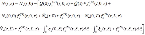
Using equation (6) and integrating equation (11) by parts, equation (11) can be rewritten as follows (Eq. 12):
 |
(12) |
where z+ and z- represent the vertical coordinates approachingz from the down and upper sides infinitely. The difference
 of the fundamental solution strain of the layered TISS in equation (12) can be represented as follows (Eq. 13):
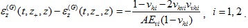 |
(13) |
Applying the above-mentioned pile-soil compatibility condition given by equation (7) and using equations (8) and (12), one has the following second kind Fredholm integral equation for the pile:
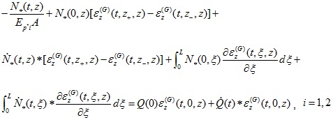 |
(14) |
To eliminate the time derivatives and convolutions in equation (Eq. 14), the Laplace transform should be invoked. The Laplace transform and the corresponding inverse transform are defined as follows [31], (Eq. 15)
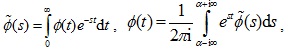 |
(15) |
where the variable with a tilde denotes the variable in the Laplace transformed domain; s is the Laplace transform parameter; and α is a parameter associated with the Laplace transform. Taking Laplace transform on equation (14) with regard to time t, the second kind Fredholm integral equation of the pile is reduced to (Eq. 16):
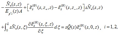 |
(16) |
in which the variable with a tilde denotes the variable in the Laplace transformed domain.
The axial force of the real pile can be obtained by adding the axial force of the fictitious pile to the force acting on
. Likewise, it can be represented as follows (Eq. 17):
 |
(17) |
where
 is the time-dependent fundamental solution representing the force acting on
at time t caused by a unit uniformly-distributed load acting over
from time zero with the compressive force considered to be positive. The force
is the time-dependent fundamental solution representing the force acting on
at time t caused by a unit uniformly-distributed load acting over
from time zero with the compressive force considered to be positive. The force
 can also be obtained by the fundamental solution given in [30]. The appearance of the negative sign before the brace is because the sign convention for the normal stress of the soil and that of the pile are opposite.
Similarly, applying the integration by parts and the Laplace transform to equation (17), one has the following axial force for the real pile in the transformed domain (Eq. 18):
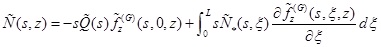 |
(18) |
Besides, by following the similar procedure, the vertical displacement of the pile in the Laplace transformed domain can be obtained as follows (Eq. 19):
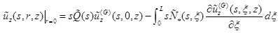 |
(19) |
where
 is the transformed vertical displacement of the pile;
 is the transformed fundamental solution denoting the vertical displacement at the center
of caused by the unit uniformly-distributed load acting on
.
is the transformed fundamental solution denoting the vertical displacement at the center
of caused by the unit uniformly-distributed load acting on
.
The transformed pore pressure in the layered TISS along the side of the pile can also be obtained by means of the axial force of the fictitious pile and the corresponding fundamental solution of the pore pressure of the layered TISS as follows (Eq. 20):
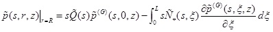 |
(20) |
in which
 denotes the pore pressure of the TISS along the side of the pile;
 is the fundamental solution associated with the transformed pore pressure of the layered TISS at the periphery of
due to the unit uniformly-distributed load acting over
.
is the fundamental solution associated with the transformed pore pressure of the layered TISS at the periphery of
due to the unit uniformly-distributed load acting over
.
3.2. Numerical Solution of the Second Kind of Fredholm Integral Equation of the Pile
In this study, the technique used by Niumpradit & Karadushi in [21] to solve the Fredholm integral equation of the pile is employed. According to Niumpradit & Karadushi [21], the integral along the pile embedded in the ith soil layer is divided evenly into
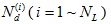 number of segments with two end nodes delimiting each segment, in which NL is the number of the soil layers in contact with the pile. Hence, the total segments used to discretize the pile is equal to
 . Due to the presence of interfaces between soil layers and the discontinuity of the axial force of the fictitious pile at the interface, two nodes belonging to different segments of the pile and coinciding at a soil interface should be treated as two different nodes. Hence, the total number of nodes is equal to Np = Nd + NL.
Adopting the method proposed in [21], the integral in Eq. (16) over the segment of the pile with the end nodes zj and zj+1 is evaluated as follows:
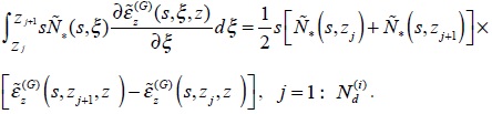 |
(21) |
Applying the above Eq. (21) to Fredholm integral Eq. (16), the following system of Np linear equations can be obtained.
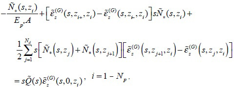 |
(22) |
By solving Eq. (22), Np discrete axial force of the fictitious pile can be obtained numerically. As mentioned above, once the axial forces for the fictitious pile is obtained, the axial force of the pile, the vertical displacement and the pile-side pore pressure of the layered TISS can all be determined numerically using corresponding equations.
Note that the obtained solution for the pile is in the Laplace transformed domain. In order to retrieve the solution in the time domain, the inversion of the Laplace transform has to be performed numerically. In this study, the inversion of the Laplace transform is accomplished by using the Schapery’s method [32]. According to the Schapery’s method, the function in the time domain can be retrieved by the corresponding function in the Laplace transformed domain via the following formula (Eq. 23):
 |
(23) |
where f(t) and
 represent the function in the time domain and Laplace transformed domain, respectively.
4. NUMERICAL RESULTS AND CORRESPONDING ANALYSES
In this section, numerical results for the response of a vertically loaded pile embedded in a layered TISS obtained by the proposed model are presented. First, to validate the proposed model, results of this paper are compared with those of two existing solutions. Then, a parametric study on the effect of different parameters on the behavior of the pile in a layered TISS is conducted.
For convenience of presentation, the following non-dimensional quantities are defined (Eq. 24)
 |
(24) |
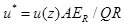
in which, LR, µR and kR are referred to as the reference length, reference shear modulus and reference permeability; the quantities z*, r*, t*, u*, N*, p* and Q* represent the dimensionless depth, radius, time, displacement, axial force of the pile, pore pressure, and the applied load, respectively.
4.1. Validation of the Proposed Model
4.1.1. Convergence Test of the Proposed Model
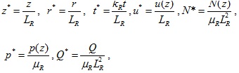
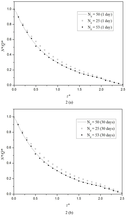
In this section, three different discretization schemes corresponding to three total numbers of the discretization segments of the pile, namely, Nd = 25, 50, and 53, are used to examine the stability and convergence of the proposed numerical model. For all three schemes, the stiffness ratio η = 0.5 is used for a stratified soil consisting of two overlying soil layers and one underlying half-space layer with the shear moduli ratio µv1: µv2: µv3 = 1:1:2. The values of the soil parameters are tabulated in Table 1 and the pile parameters are as follows: length L = 20m, radius R = 0.25m, and the Young’s modulus Ep = 2.6 × 10⁹Pa. The solutions for the times of 1 day and 30 days (s) are considered in this example. The thickness, shear modulus µv and coefficient of vertical permeability kv of the first soil layer are chosen as the reference length LR, reference shear modulus µR, and reference coefficient of permeability kR, respectively. As shown in Figs. (2 and 3), the non-dimensional pile axial force N* and vertical displacement u* of the pile become convergent when Nd = 50-53. Therefore, in all numerical examples in this study, the total number of segments Nd = 50 is used.
| Layer Number | h/m | Ev/Pa | µv/Pa | kv,kη/m.s-1 | vh | vhv | γw/N.m-3 |
|---|---|---|---|---|---|---|---|
| 1 | 8 | 2.6×10⁷ | 1.0×10⁷ | 1.2×10⁻⁷ | 0.3 | 0.3 | 9.8×10³ |
| 2 | 8 | 2.6×10⁷ | 1.0×10⁷ | 1.2×10⁻⁷ | 0.3 | 0.3 | 9.8×10³ |
| 3 | - | 5.2×10⁷ | 2.0×10⁷ | 1.2×10⁻⁷ | 0.3 | 0.3 | 9.8×10³ |
4.1.2. Comparison with Existing Solutions
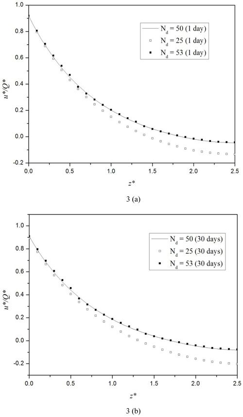
Niumpradit & Karasudhi [21] obtained the final solution for the axial force of the axially loaded pile embedded in the isotropic poroelastic half-space. To compare our results with the final solution of [21], the time is assigned a large value and the relevant parameters are set as: the pile length-diameter ratio L/d = 20; the soil Poisson’s ratio vh = vhv = vvh = 0.25 and, η = Eh / Ev = 1 where Eh and Ev are the soil’s horizontal and vertical Young’s moduli. As depicted in Fig. (4a), the pile axial forces corresponding to the above parameters and different pile-soil Young’s modulus ratio (Ep / Ev) obtained by the proposed model in this study agree with those obtained by Niumpradit & Karasudhi [21], thus, validating the proposed model.
Ai et al., [9] investigated the influence of the stratification of the soil on the response of the pile at different times. Two different cases, namely, Case 1 corresponding to a single layer half-space and Case 2 a stratified soil consisting of three isotropic layers with the shear moduli ratio equal to µv1 : µv2: µv3 = 1:2:3 are considered in their research, wherein the subscripts 1, 2 and 3 represent the first layer, second layer and third layer, respectively. Other parameters for the pile-soil system are as follows: The pile length-diameter ratio L / d = 20; the soil Poisson’s ratio; h = hv = 0.3; the pile-soil Young’s modulus ratio; Ep / Es = 300; the coefficient of permeability kh = kv = 1.2 10-6 ms-1; the soil layer’s thicknesses for the second case are h1 / d = h2 / d = 10 ; the soil stiffness ratio is η = Eh / Ev. In this example, the non-dimensional vertical displacement and time are defined as
 and,
and,
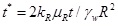 in which the reference ER, µR, and kR are taken as the vertical Young’s modulus, shear modulus and coefficient of the vertical permeability of the first layer, respectively; R is the radius of the pile and γw = 9.8 103Nm-3. Figs. (4b, and c) show clearly that the pile axial force and the dimensionless vertical displacement obtained by the proposed model agree with those obtained by Ai et al., [9] for a vertically loaded pile in a multilayered saturated soil perfectly, validating the proposed model again.
4.2. Numerical Results for a Pile Embedded in a Layered TISS
In this section, different examples are used to investigate the influence of several soil parameters on the response of the vertically loaded pile in the layered TISS. For all examples in this section, the layered half-space TISS consists of two overlying layers and one underlying half-space. Also, as mentioned above, when conducting numerical simulations, the pile is divided into 50 equal segments in all examples.
4.2.1. Influence of the Soil Stiffness Ratio and the Stiffness of the Middle Layer
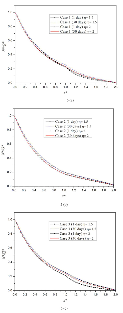
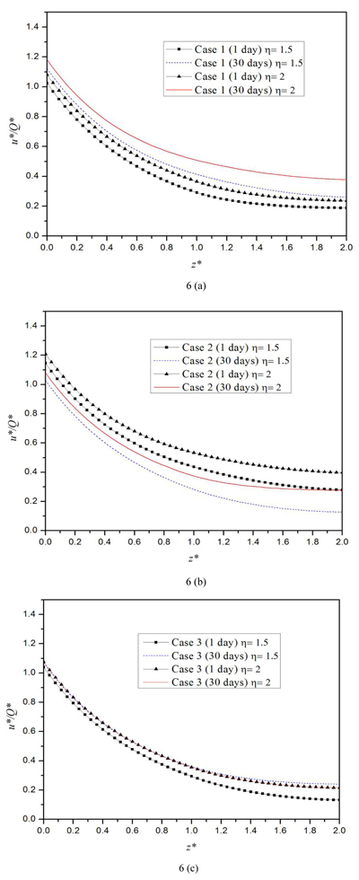
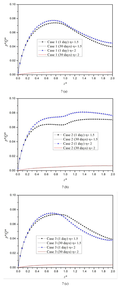
In this section, the influence of the moduli of the middle layer and the stiffness ratio η= Eh / Ev on the response of a vertically loaded pile embedded in the three-layered half-space TISS is examined. Two different stiffness ratios η = 1.5 and η = 2 are used to show the influence of the horizontal Young’s moduli. For each stiffness ratio η, three cases with each corresponding to a specific middle layer with different modulus are considered: Case 1 corresponds to a three-layered TISS with a harder middle layer; Case 2 a three-layered TISS with a softer middle layer; and Case 3 a homogeneous half-space TISS. The values of soil parameters for both η = 1.5 and η = 2 are presented in Table 2. The parameters for the pile are as follows: length L = 20 m, radius R = 0.3m and the Young’s modulus Ep = 2.5 × 10⁹Pa. In this section, the thickness, shear modulus µv and coefficient of vertical permeability of the first soil layer are used as the reference length LR , reference shear modulus µR, and reference coefficient of permeability kR, respectively.
| Layer Number | h/m | Case 1 | Case 2 | Case 3 | kv, kn/m-1 | vn | vhv | γw/N.m-3 | |||
|---|---|---|---|---|---|---|---|---|---|---|---|
| Ev/Pa | µv/Pa | Ev/Pa | µv / Pa | Ev / Pa | µv / Pa | ||||||
| 1 | 10 | 2.5×10⁷ | 1.0×10⁷ | 2.5×10⁷ | 1.0×10⁷ | 2.5×10⁷ | 1.0×10⁷ | 1.2×10⁻⁷ | 0.25 | 0.25 | 9.8×10³ |
| 2 | 10 | 5.0×10⁷ | 2.0×10⁷ | 1.25×10⁷ | 0.5×10⁷ | 2.5×10⁷ | 1.0×10⁷ | 1.2×10⁻⁷ | 0.25 | 0.25 | 9.8×10³ |
| 3 | - | 2.5×10⁷ | 1.0×10⁷ | 2.5×10⁷ | 1.0×10⁷ | 2.5×10⁷ | 1.0×10⁷ | 1.2×10⁻⁷ | 0.25 | 0.25 | 9.8×10³ |
Fig. (5) shows that for all cases, the axial force of the pile decreases with the increase of the depth. In addition, both the stiffness ratio and the Young’s modulus of the middle layer have a little influence on the axial force of the pile. However, at some depth near the soil interface, the axial force of Case 3 is smaller than those of the other two cases. Similarly, Figs. (6a, b) shows that the vertical displacement of the pile also decreases as the depth increases. It is also shown in Fig. (6) that for both Cases 1 and 2, a larger stiffness ratio corresponds to a larger vertical displacement. The vertical displacement increases with time in the harder middle layer case, and it decreases with time in the softer middle layer case. As depicted in Fig. (7a), the pore pressure on the pile-side tends to zero as the time increases. For all three cases, the pore pressure at the top of the pile vanishes, since the top of the half-space soil is assumed to be permeable. For both Cases 1 and 3, the pore pressure first increases and at one depth it reaches a marked peak and then it decreases. For both the hard and soft middle layer cases (Cases 1 and 2), the pore pressure increases with the increase of the stiffness ratio, while for the case of homogeneous half-space (case 3), there exists an intersection point in the second layer. Before this point, the pore pressure increases with the increase of the stiffness ratio; after the point, opposite scenario occurs. Meanwhile, it follows from the figure that in the second layer of the half-space, the pore pressure of Case 2 is the largest among the three.
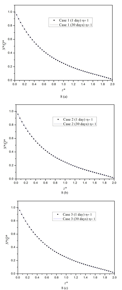
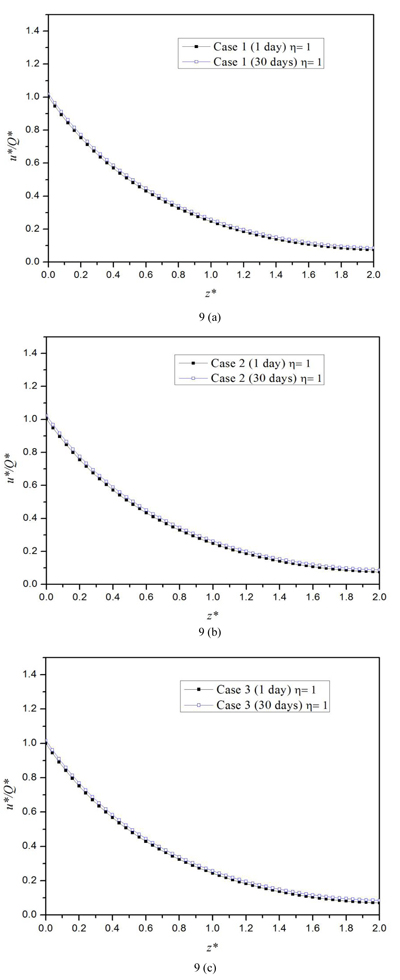
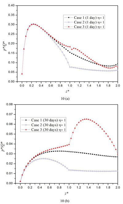
4.2.2. Effect of the Permeability of the Middle Layer
In this section, the influence of the permeability on the behavior of the pile embedded in a three-layered half-space TISS is investigated. The half-space TISS in this section is also composed of by two overlying layers and one underlying layer, i.e., the underlying half-space. Three cases are considered in this section. For Case1, all three layers have equal permeability; Case2 corresponds to a high permeable middle layer; Case 3 to a less permeable middle layer. The parameters for the pile in this section are as follows: length L = 20m, radius R = 0.3 m and the Young’s modulus Ep = 2.5 × 10⁹Pa, while the parameters for the soil are shown in Table 3. Similarly, the thickness, shear modulus µv and coefficient of vertical permeability of the first soil layer are set as the reference length LR, reference shear modulus, µRand reference coefficient of permeability kR, respectively.
| Layer Number | h/m | kv, kh/m-1 | vn | vhv | γw/N.m-3 | Eh/Pa | Ev/Pa | µv/Pa | ||
|---|---|---|---|---|---|---|---|---|---|---|
| Case 1 | Case 2 | Case 3 | ||||||||
| 1 | 10 | 1.0×10⁻⁸ | 1.0×10⁻⁸ | 1.0×10⁻⁸ | 0.25 | 0.25 | 9.8×10³ | 2.5×10⁷ | 2.5×10⁷ | 1.0×10⁷ |
| 2 | 10 | 1.0×10⁻⁸ | 1.0×10⁻⁷ | 1.0×10⁻⁹ | 0.25 | 0.25 | 9.8×10³ | 2.5×10⁷ | 2.5×10⁷ | 1.0×10⁷ |
| 3 | - | 1.0×10⁻⁸ | 1.0×10⁻⁸ | 1.0×10⁻⁸ | 0.25 | 0.25 | 9.8×10³ | 2.5×10⁷ | 2.5×10⁷ | 1.0×10⁷ |
Figs. (8 and 9) show that the influence of the permeability of the middle layer is almost negligible. Also, it can be seen that for all three cases, the vertical displacement increases as time increases. Moreover, both the axial force and vertical displacement decrease with the depth. Besides, as illustrated in Fig. (10), the permeability of the middle layer has a significant influence on the pore pressure. The pore pressure is the largest when the half-space’s middle layer is less permeable, i.e., Case 3, and smallest when the middle layer is highly permeable. The pore pressure at 30 days is much smaller than that at one day, which indicates that the pore pressure will dissipate with time for all three cases. Fig. (10a) shows that at the time of one day, the variation of the pore pressure for the three cases are similar: it first increases with the depth; then, it achieves a peak value at certain depth in the first layer; lastly, it will decrease with the depth.
CONCLUSION
The integral equation model for a vertically loaded pile embedded in a layered TISS is established in this study. The corresponding fundamental solution for the half-space TISS is obtained via the RTM method. Numerical results obtained by the proposed model are compared with those of existing solutions and a good agreement between the two solutions is observed. The parametric study presented in this paper shows that the transverse isotropy property of the soil has a considerable influence on the behavior of the pile embedded in the layered half-space TISS. A larger stiffness ratio will lead to an increase of both the vertical displacement and the pore pressure for a three-layered half-space with a hard and a soft middle layer. Besides, it is also found that both the vertical displacement and the axial force of the pile decrease as the depth increases. Also, for a three-layered half-space TISS, the vertical displacement increases with time for the harder middle layer case, and it decreases with time for the softer middle layer case. As expected, the pore pressure along the pile-side tends to zero as the time increases. The permeability of the middle layer of the three-layered half-space TISS soil has a considerable influence on the pore pressure along the pile-side. The pore pressure is the largest for the case of the less permeable middle layer, while it is the smallest for the case of the most permeable middle layer. Besides, due to the permeable assumption for the soil surface, the pore pressure tends to zero at the top of the pile.
The proposed model provides a valuable tool for estimation of the response of a single pile embedded in a layered half-space TISS. In the further study, more engineering problems, such as the problem of the pile embedded in the layered TISS subjected to horizontal forces and the problem of pile groups in the layered TISS can be considered. However, since the proposed model in this study is for the TISS with linear constitutive relation undergoing small deformation, the proposed model is hence inapplicable to the cases involving non-linear constitutive relations and large deformations.
CONSENT FOR PUBLICATION
Not applicable.
CONFLICT OF INTEREST
The authors declare no conflict of interest, financial or otherwise.
ACKNOWLEDGEMENTS
Financial supports received from the National Natural Science Foundation of China (No. 11272137) and Jiangsu Province (BK20150512 Youth Funding) are highly acknowledged by the authors. Also, the constructive comments from two anonymous reviewers are highly appreciated by the authors.

