All published articles of this journal are available on ScienceDirect.
Numerical Study on Bearing Capacity and Bulging of the Composite Stone Column
Abstract
Background:
In weak clay soil, a proper ground improvement technique using a stone column can be limited by the absence of sufficient lateral confining pressure. Stone columns should be strengthened to provide the minimum required lateral confining pressure.
Objective:
The aim of this study is to find out the significant improvement of the composite stone columns compared to the conventional stone columns by comparing the bearing capacity enhancement and the treated soil stiffness for both models. Composite stone columns with a solid concrete part at the top-head not only enhance the bearing capacity of the stone columns but also decrease the bulging failure and increase the surrounding soil stiffness.
Methods:
The 2D finite element analyses were carried out to simulate an experimental study conducted by Ambily and Gandhi on conventional stone columns. ABAQUS software program with the Mohr-Coulomb criterion for soft clay soil and stones was used in the simulation. First, a preliminary numerical model was created to simulate the experiment model. Similar material properties, boundary conditions, and constraints were considered in the preliminary model. The results were compared, and they were similar to the experimental results. During this process, the efficiency of the numerical model was confirmed. Second, the same numerical model was performed for the composite stone columns without modifying the material properties, boundary conditions, and constraints of the preliminary model. The parameters that influence the composite stone column bearing capacity as the length of the concrete part, the stress concentration ratio, and the shear strength of the surrounding soil, were all studied.
Results:
The data obtained from the aforesaid study was used along with ABAQUS software package. Compared to existing work, our approach achieves a significant correlation, and it indicates that the solid concrete part increases the surrounding soil stiffness, in addition to increasing the bearing capacity of the stone column. The solid concrete part resists bulging deformation by moving the bulging failure downward where the confining pressure is larger. The stress concentration ratio increases with the length of the solid concrete part.
Conclusion:
Composite stone columns have a significant influence on the improvement of weak clay soil and increase the bearing capacity of soil under superstructures. Furthermore, they also increase the stiffness of weak soil around the column. The magnitude of weak soil improvement by using composite stone columns is greater than conventional stone columns. Therefore, composite stone columns are more efficient and effective than conventional stone columns.
1. INTRODUCTION
The composite stone columns are a useful, cost-effective, and environmentally friendly method for improving the low bearing capacity and large-scale settlement of weak soil and has been widely used in soft soil foundation reinforcement. Granular columns, which are usually referred to as stone columns, sand columns, or granular piles, consist of compacted sand or gravel that is inserted into weak soil using various types of installation techniques [1-4]. Stone columns are sometimes called flexible piles due to their flexibility [5]. The comparison of flexible and rigid piles shows that the vertical bearing capacity of stone columns mainly depends on the lateral resistance of the surrounding soil. However, the confining pressure near the ground soil is relatively small; therefore, the stone columns are prone to bulge and fail within the depth approximately four times the diameter of the column [6-10]. The Indian Standard Guidelines also refer to the same results reported by previous studies [11]. Therefore, engineers have proposed many methods to improve the bearing capacity of granular piles. However, the treatment effect is still affected by the lateral resistance of the near-ground surface weak soil. Moreover, many researchers focused on multiple methods to improve the ultimate bearing capacity of stone columns. For example, the analyses of swelling, deformation, stress ratio, and settlement were studied through experiments and numerical simulations.
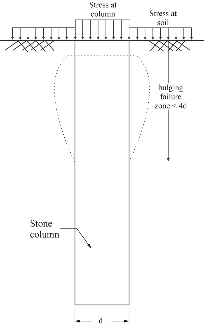
In geotechnical engineering, the two main criteria that govern the design and performance of footings are the bearing capacity and settlement. A stone column’s bearing capacity mainly depends on the confinement pressure provided by the surrounding weak soil [12]. A previous experimental investigation revealed that the applied load is transmitted from the column body to the surrounding soil, and a small magnitude of the load is transmitted to the bottom of the column [7, 13]. The top weak soil layer has a significant impact on the total stiffness, load-bearing capacity, and bulging behavior of stone columns. The presence of a strong top layer, such as sand, improves the strength and stiffness of weak soil [14, 15]. The stiffness and load-carrying capacity of stone column treated soil decreases with the increase of the top weak layer thickness. Fig. (1) shows the bulging failure that occurs within 4 times the diameter of the granular column. However, numerical and experimental indications signify that even bulging can occur in depths less than 2-3d [13, 16, 17]. Similar experiment results indicate that bulging failure occurs at a depth of 1.0d to 2.5d [18]. The swelling problem and its effect on weak soil bearing capacity were investigated [19], and bulging and excessive settlement caused by swelling was studied based on the modified strain wedge model [20]. Ambily and Gandhi conducted an experimental and numerical study and found that when the column area alone is loaded, the maximum bulging failure is at a depth of approximately 0.5d [21].
Encasement and grouting are among many different methods for reducing bulging to achieve a high stone column bearing capacity. The composite stone column idea combines the advantages of different conventional stone columns. The bearing capacity of composite stone columns is higher than that of conventional stone columns at a competitive cost, and they have a higher load capacity than the bore pile of the same peripheral size and length. In addition to these advantages, composite stone columns can result in significant resistance against bulging failure [5]. Bulging deformation moves down with the increasing length of the solid concrete part; also, the stiffness of a composite stone column increases with the existing solid part near the ground surface [20, 5]. The characteristics of the stone column further change due to the solid concrete part.
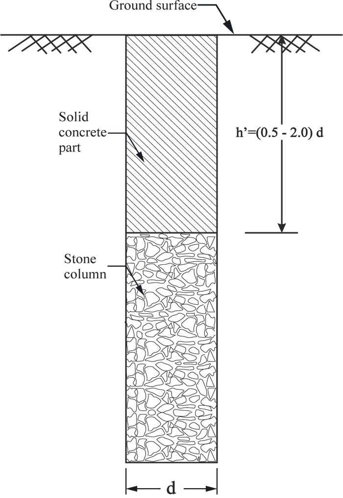
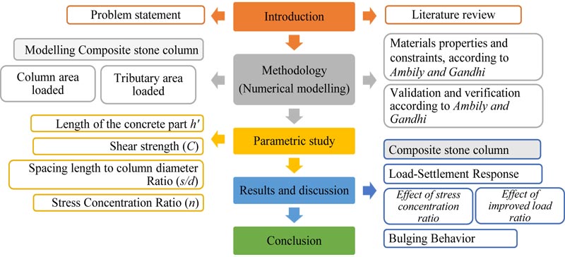
As mentioned earlier, this numerical analysis study was performed to study the effects of solid concrete part on the composite stone column behavior as shown in Fig. (2) (Sand-concrete composite column) [22]. An ABAQUS software package was used for numerical analysis verification. The numerical model for validation was approved by the previous studies, and the same material properties and boundary conditions were selected as in the numerical, analytical study conducted by A. P. Ambily and S. R. Gandhi [21]. After asserting the validity of the numerical model, four models of composite stone columns were utilized, taking into account the same material properties and boundary conditions. First, Conventional stone column results were compared with the experimental and numerical study of a previous study; the results indicate an ideal agreement. Second, The numerical modeling shape was changed while preserving the previous parameters and conditions. Fig. (3) shows a flowchart of the research methodology.
2. MATERIALS AND METHODS
2.1. Numerical Analyses
2.1.1. Model Validation
The finite element software ABAQUS (ABAQUS/CAE 2017) was selected to take advantage of its durability in the numerical analysis solution strategy for soil nonlinearity. Many researchers have used ABAQUS for numerical modeling [23, 24], such as simulated encased stone columns and retaining walls using geosynthetic material [25-28]. In this numerical analysis, a 2D finite element analysis method based on ABAQUS was used to verify the numerical analysis accuracy, and a reasonable comparison was made with the existing model load tests on stone columns presented by Ambily and Gandhi [21]. Three different model sizes of unit cells were filled with homogeneous clayey soil, and the unit cell diameters ranged from 420 mm - 210 mm. These models were used in the model test with the same 500 mm height [21]. According to the model load test, the relationship of the unit tank diameter to the stone column diameter was considered as s/d=2, s/d=3, and s/d=4. They were denoted by model-1, model-2, and model-3, respectively, in this study. A stone column of 100 mm diameter and 450 mm height was installed at the center of the clay bed and loaded with a loading plate whose diameter was equal to the stone column diameter [21]. The material properties recorded in the paper and later used in the analysis are presented in Table 1.
| Properties | Materials | |
| Clay | Stone | |
| Modulus of elasticity (kPa) | 5500 | 55,000 |
| Poisson’s ratio (v) | 0.42 | 0.3 |
| Angle of fraction (ϕ) | 0 | 38 |
| Dilatancy angle (ψ) | 0 | 4 |
| Shear strength (kPa) | 30 | 0 |
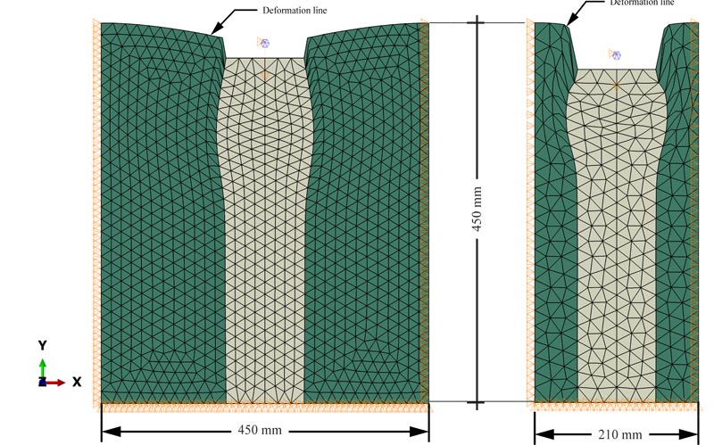
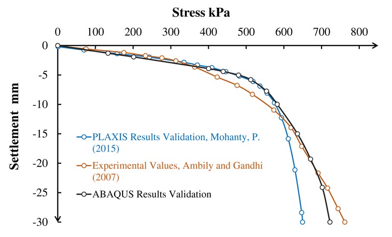
Previous studies carried out 2D numerical analysis using the elastoplastic Mohr-Coulomb failure criterion [29, 21]. Fig. (4) shows the finite-element discretization using six-node modified quadratic plane strain triangle elements with boundary conditions. All nodes along the model lateral periphery were restrained from moving in radial directions, and all nodes at the model bottom surface were restrained from moving in both radial and vertical directions; also the top surface was free to move in any direction. The interface friction between the stone columns and the surrounding soil was considered in the simulation, and tie constraints were used (i.e., no-slip or separation of the interfaces). Tie constraints displayed perfect bonding between the stone columns and the surrounding soil at their interfaces. The interface of the stone particles and clayey soil was a mixed zone, and the shear strength of the interface was expected higher than that of the clayey soil [21, 30]. Researchers have considered the tie constraint interface in numerical model studies on groups of stone columns and encased stone columns [31, 32]. The model load-settlement test behavior conducted by Ambily and Gandhi [21] and its numerical validation performed by Mohanty and Samanta using PLAXIS [22] were compared with the present validated numerical analysis based on ABAQUS as illustrated in Fig. (5). ABAQUS numerical analysis validation was also compared with model load tests for model-2 and model-3, as shown in Fig. (6). A closer match can be observed between the model load test and the present ABAQUS analysis than that between the model load test and the PLAXIS analysis. The gravity effect was considered in the ABAQUS analysis.
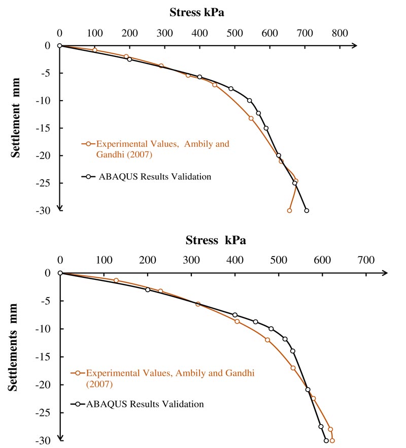
(b) Model-3: s/d=4
Validation load versus settlement curve of conventional stone column in clayey soil; a) s/d=3; b) s/d=4.
2.1.2. Analysis of Stone Column (Description of Finite Element Models)
The 2D analysis was performed using the plane strain Mohr-Coulomb failure model for the material properties of soft clay and stone as adopted by A. P. Ambily and S. R. Gandhi [21]. Furthermore, the elastic material behavior was considered for concrete. Initial stress conditions due to gravity load were considered in the analysis. However, the stress caused by the column installation method was not considered in the analysis. The input parameters are provided in Table 2. A normal plan concrete with a compression strength of 20 MPa was used for modeling. Fig. (7) shows general 2D finite-element boundary conditions and mesh used to simulate the stone column and surrounding soft clay.
3. RESULTS AND DISCUSSION
3.1. Parametric Study
All the numerical analyses were conducted with the unit cell geometry idea. Numerical analysis was conducted on single composite stone columns with solid concrete parts of different lengths 0.5, 1.0, 1.5, and 2.0 times the diameter. The diameter of the stone column was 100 mm for all models, and the tank diameters (spacing) were 210, 315, and 420 mm [21]. The critical loading area that provided maximum improvement was 2.5 times the diameter of the stone column [33]. Spacing more than 3 times the diameter of the column did not bring any significant enhancement [21]. Therefore, the tributary area loaded was 2.3 times the stone column “Effective Loaded Area,” and the case where the column area loaded was considered as well, similar to the previous study [31]. The results of the numerical model and the parametric studies are mentioned in the following sections.
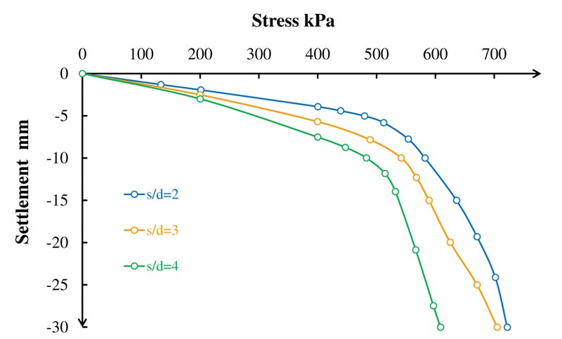
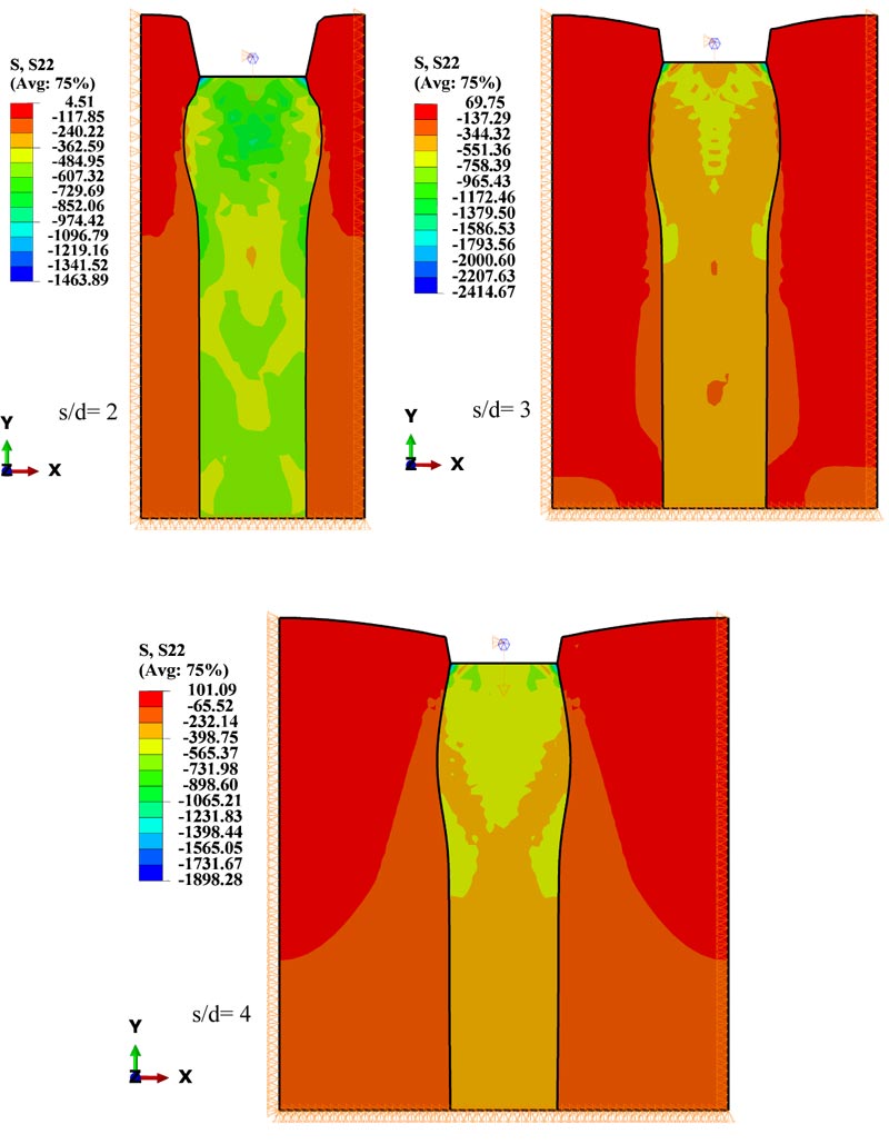
In the case of the column area loaded, the typical axial stress versus the settlement behavior of the stone column and clay soil relationships for the three models are compared. Fig. (8) shows the stress-settlement behavior of the conventional stone column in various cases of s/d (spacing/diameter). The model-1 showed the maximum axial vertical stress. The axial vertical stress decreased with an increase in the unit cell diameter (spacing), which was related to the significance of the confining pressure provided by the smallest diameter of the unit cell.
| Properties | Materials | ||
| Clay | Stone | Concrete | |
| Modulus of elasticity (kPa) | 5500 | 55,000 | 30,000,000 |
| Poisson’s ratio (v) | 0.42 | 0.3 | 0.17 |
| Shear strength (kPa) | 30 | 0 | - |
| Angle of internal friction (ϕ) | 0 | 38 | - |
| Dilatancy angle (ψ) | - | 4 | - |
| C-bulk (kN/m3) | 18.8 | 16.2 | 24 |
| Compression strength (kPa) | - | - | 20,000 |
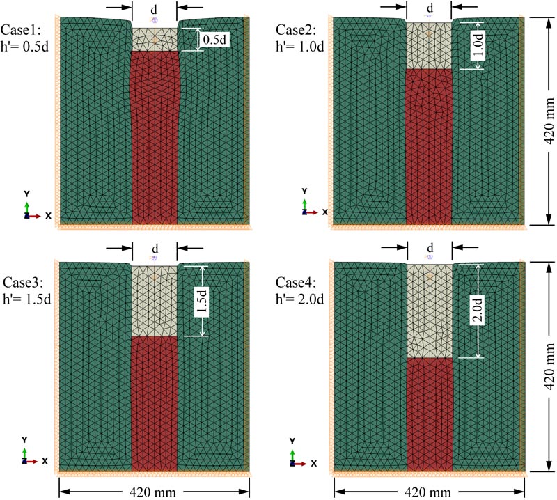
Fig. (9) shows the distributions of vertical stress in the stone column and the surrounding soil of different models. Moreover, for the tributary area loaded case, the entire area of model-1 was loaded, and the model-2 was loaded on an area of 2.3d diameter. For both models, no failure occurred even at a high settlement because of the confining pressure effect produced by the boundaries of the unit cell, and this aspect was consistent with A. P. Ambily and S. R. Gandhi [21].
Superstructure loading was not only applied to stone columns but also on the surrounding soil. Furthermore, the failure behavior was not observed in the tributary area load case for both model-1 and model-2. Consequently, the stress concentration ratio could not be calculated. Therefore, the model-3 was investigated in both loading cases to calculate the stress concentration ratio.
3.2. Load-Settlement Response
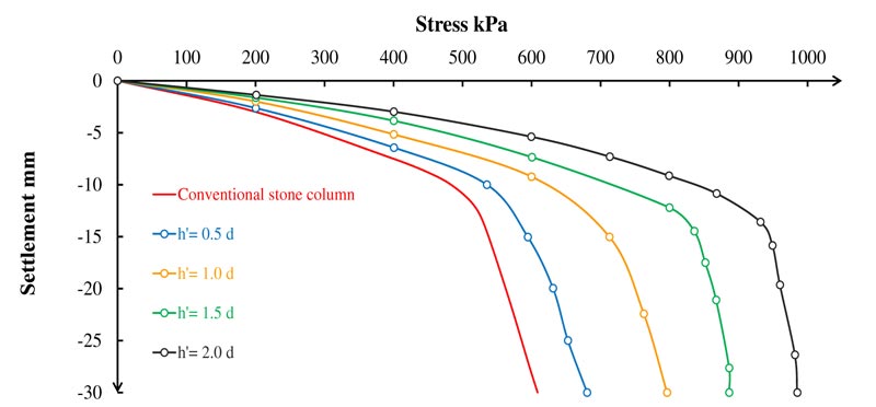
The presence of the stone columns develops the bearing capacity of the weak soil. Further, stone columns can improve 50 - 75% of the soil ultimate bearing capacity [34, 35]. In agreement with this instance, the composite stone column also has a relatively high bearing capacity due to the excessive stiffness produced by the solid concrete part [5]. The upper portion of the composite stone column is a solid concrete part with normal strength, which aims to increase the bearing capacity of the column by developing a high-stiffness area near the ground surface and resisting bulging failure. Axial vertical stress versus settlement in column area loaded case for the model-3 is shown in Fig. (10). The figure shows that the axial vertical stress increased with the length of the solid concrete part. The solid concrete part increases the stiffness of the column, which enhances the bearing capacity of the column.
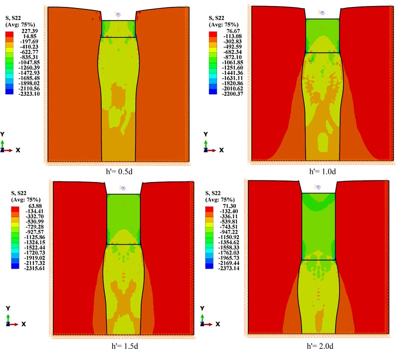
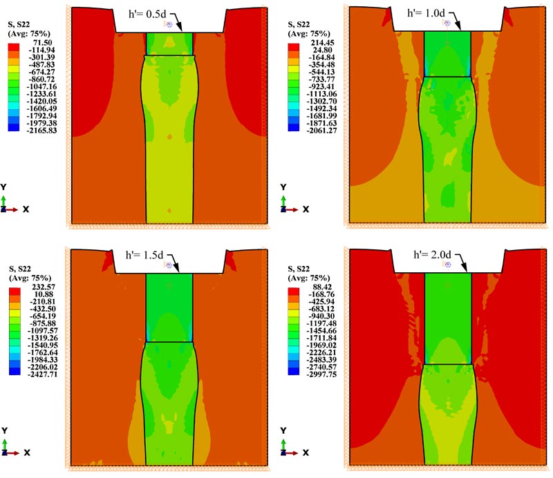
Fig. (10) shows that the axial vertical stress increased with the length of the solid concrete part (h'). The maximum axial vertical stress of the conventional stone column was approximately 600 kPa at 30 mm settlement. When h' was near the half-length of the stone column, the stress increased by 60%. The results were consistent with a study conducted on the bearing capacity of composite stone columns at deep layers according to the Meyerhof method. The bearing capacity of composite stone columns was higher than that of conventional stone columns; when h' was 1 m, the bearing capacity improvement was 32.76%, and when it was 2 m, the improvement value was 54.74% [20]. The solid concrete part transferred the load to lower soil layers where the confining pressure is high. Mechanically, the surrounding soil resisted the bulging of the column, and with a solid concrete part existing, the bulging would move down where the confining pressure was bigger, which in turn lead to an increase in the vertical stress of the column. The results of the ABAQUS showed the vertical stress distribution of different lengths of the solid concrete part (Fig. 11).
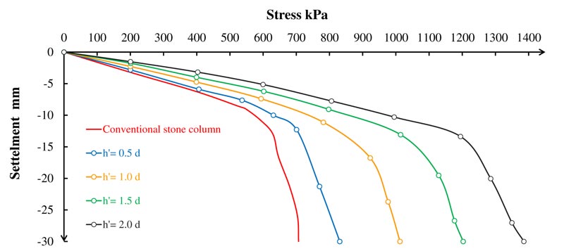
Fig. (12) illustrates the axial vertical stress versus settlement in model-3 in a tributary area loaded case. The column bearing increase capacity is similar to the column area loaded case, except for the higher magnitude of the bearing capacity. Vertical load on a large area within the stone column and the surrounding soil decreases the concentricity of the stone column vertical load. The horizontal stresses within the surrounding soil act opposite to the bulging failure direction. Furthermore, the horizontal stresses increase the confining pressure, which increases the bearing capacity of the column by resisting bulging failure. Fig. (13) shows the vertical stresses in the composite stone column and the surrounding soil. The conventional stone column bearing capacity in the tributary area loaded case is 15% more than that in the column area loaded case. This value increases with the length of the solid concrete part. Table 3 shows the percentage of increment for both loading cases.
| h' | Column Area alone Loaded Max. bearing Capacity (kPa) | Area alone Loaded Max. bearing Capacity (kPa) | Increasing of bearing Capacity % |
| 0.0d | 608 | 707 | 16.3 |
| 0.5d | 680 | 830 | 22.1 |
| 1.0d | 796 | 1012 | 27.1 |
| 1.5d | 886 | 1202 | 35.7 |
| 2.0d | 985 | 1385 | 40.6 |
3.2.1. Effect of Stress Concentration Ratio (n)
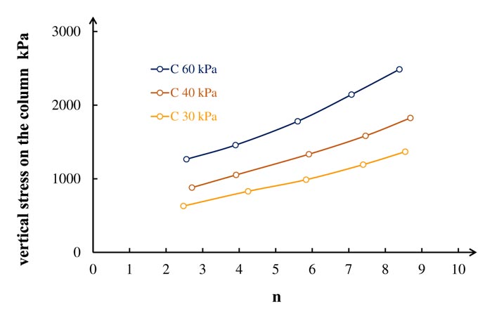
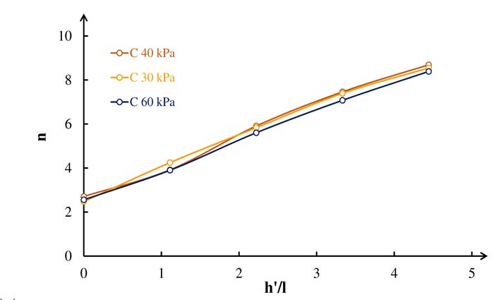
The stress concentration ratio is an important parameter that affects the bearing capacity of the stone column. When the stiffness of the stone column is high, the stress concentration ratio is more on the column than the surrounding soil. Fig. (14) reveals that increasing the stress concentration ratio will increase the bearing capacity of the column, and the soil shear strength has a big influence on the stone column bearing capacity. Table 4 presents the value of the stress concentration ratio lies between 2.5 - 8.5. This value is consistent with other studies. Indian Standard (IS:15284-2003) mentioned n value is generally considered 2.5 - 5 [11]. Further more, other studies reported that n value is 2-6 [1, 36]. Theoretical and experimental investigations revealed that the range of n is from 3 to 10 [2]. Fig. (15) shows a typical relationship between the stress concentration ratio versush'/l (concrete part length / total length of stone column). The figure presents the relationship of different shear strength (C) and constant Es/Ec = 10. The stress concentration ratio increases linearly with h'/l values. Table 4 reveals that shear strength has a small effect on the stress concentration ratio associated with h'/l thus it can be ignored.
| Shear Strength of Loess Soil | Stress Concentration Ratio (n) | ||||
| h'= 0.0d | h'= 0.5d | h'= 1.0d | h'= 1.5d | h'= 2.0d | |
| 30 | 2.47 | 4.24 | 5.83 | 7.39 | 8.55 |
| 40 | 2.71 | 3.92 | 5.91 | 7.46 | 8.69 |
| 60 | 2.56 | 3.9 | 5.6 | 7.08 | 8.39 |
3.2.2. Effect of Improved Load Ratio
The ratio of the ultimate bearing capacity of the stone column reinforced soil to the unreinforced weak soil bed at equal footing settlement is defined as the Load Ratio parameter (L.R):
 |
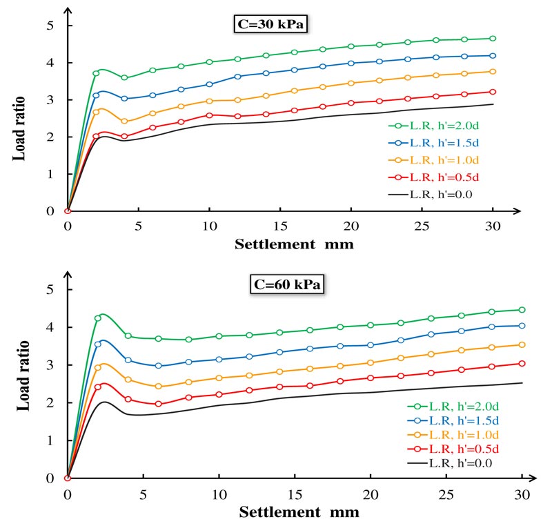
Fig. 16(a-b) show the variation of the improved load ratio corresponding to the footing settlement for different h' lengths. The lowest load ratio improvement was associated with conventional stone columns, and the highest load ratio was associated with composite stone columns where h'=2d. The maximum load ratio improvement varied from 1.92 to 3.8 for 30 kPa shear strength and from 1.92 to 4.31 for 60 kPa shear strength. The load ratio was significantly increased for composite stone columns, and it was affected by solid concrete length. Composite stone columns increased the soil stiffness and the bearing capacity of stone columns. The solid concrete part prevented column bulging near the soil surface, which greatly increased the load ratio. Moreover, the efficiency of the composite stone column in high shear strength clay soil was higher than in low shear strength clay soil; this result was consistent with previous studies [32]. The OSC load ratio was the same for both soil shear strengths. Furthermore, the load ratio of the composite stone columns was affected by the shear strength, and it increased with an increase in shear strength. In low shear strength soil, the solid concrete part increases the load ratio by 9.3, 40.5, 64, 97.9%, respectively, compared to the conventional stone column. In high shear strength soil, the increased load ratio was 28.6, 56.3, 90.6, 129.1%, respectively, as shown in Fig. 16(a-b). The maximum load ratio of the stone columns was measured at a 2% settlement ratio. In most models, the load ratio gradually decreased after the maximum settlement ratio values were attained.
3.3. Bulging Behavior
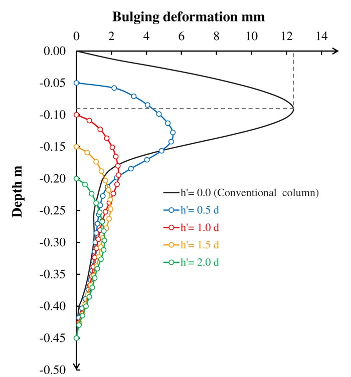
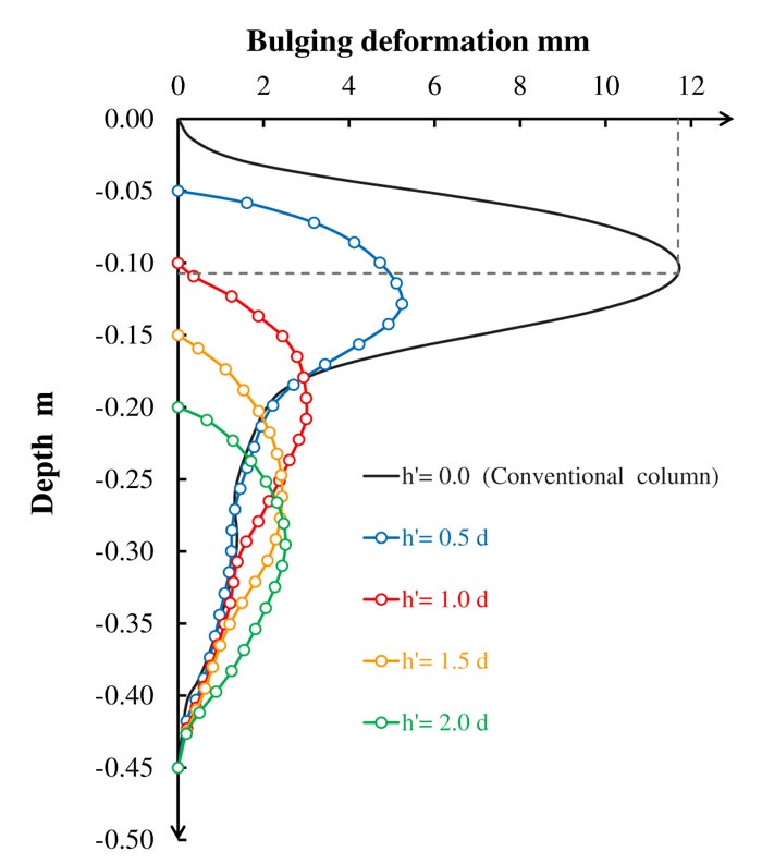
Bulging deformation is considered an indicator of stone column bearing capacity. Increasing the bulging deformation will decrease the bearing capacity of the stone column. Fig. (17) shows the bulging deformation in the case of the column area loaded. The figure presents that the maximum bulging of the conventional stone column occurs at an approximately one-time depth of the stone column diameter. This value is consistent with previous studies [16]. The first model with h'=0.5d solid concrete part shows significantly high resistance to bulging failure with more than 50% reduction compared with the conventional stone column; this noticeable improvement also corresponds to the geosynthetic encased stone columns [17, 32]. The second model with h'=1.0d solid concrete part indicates greater resistance to bulging failure with more than 90% reduction compared with the conventional stone column. The third and fourth models show a small reduction in bulging deformation, indicating that no more bulging improvement will occur deeper than 1.5 times the diameter of the stone column. Table 5 presents that the maximum bulging occurs at 90 mm (≈1d) depth and remains nearly constant in all models. The tributary area loaded case shows nearly the same behavior as in the column area loaded case, except for slight bulging improvement, as shown in Fig. (18).
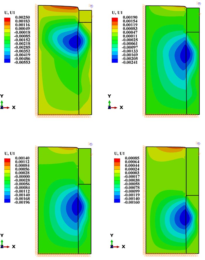
Fig. ( 19) illustrates the horizontal deformation distribution within the composite stone column and surrounding soil. Vertical load in all four models is equal to the total vertical load on the conventional stone column, causing 30 mm displacement. The horizontal deformation becomes smaller with an increase in the length of the solid concrete part, as shown in the figure.
| The Height of the Concrete Part | Max. Bulging (mm) | Depth of Max Bulging from the Stone Column Top (mm) |
| 0.0d | 12.41 | 90.0 |
| 0.5d | 5.51 | 77.5 |
| 1.0d | 2.41 | 93.0 |
| 1.5d | 1.95 | 96.5 |
| 2.0d | 1.60 | 95.0 |
CONCLUSION
The performance of the composite stone column reinforced clayey soil was investigated in the present study. 2D finite element analysis using ABAQUS computer software was used. Composite stone columns having four different lengths of the solid concrete part (0.5, 1, 1.5, and 2 times the column’s diameter) were studied. Ultimate bearing capacity and the bulging failure were investigated for both two cases (column area loaded and tributary area loaded), and different shear strength of the clayey soil was considered during the investigation as well.
The following conclusions are drawn from the observations of the present work.
- The stress-settlement response of composite stone columns could be significantly improved by the solid concrete part. Solid parts at the top of the column increased the stiffness, leading to high vertical stresses with little settlement. Vertical stress in the model-2 was higher than that in model-3 due to the high confining pressure in small unit cell diameter. When the diameter of the unit cell was less than 3 times the stone column diameter, the bearing capacity was high.
- The solid concrete part length affected the bearing capacity of the stone column. When h'=2.0d, the increase in maximum bearing capacity of the column was about 60% in the column area loaded case and approximately 90% when the tributary area was loaded. This enhancement was due to the horizontal stress generated within the top layer of the soil.
- Bulging is an important parameter that affects the capacity of the column. The solid concrete part increases the stiffness near the ground surface; thus, the bulging moves deeper where the confining pressure is sufficient to resist bulging deformation. The results indicate that the bulging decreased by more than 50% when h'= 0.5d. In addition, the bulging deeper than 1.5 times the diameter is slightly smaller, and no bulging decrease occurred.
- The stress concentration ratio of the conventional stone columns was nearly 3%, which was consistent with the results of previous studies. Increasing the length (h') of the solid concrete part would increase the stress concentration ratio. Soft clayey soil’s shear strength had a small effect on the stress concentration ratio of the stone columns. In contrast, soil shear strength had a significant influence on stone column bearing capacity. The stress concentration ratio was associated with stiffness of the column and surrounding soil. In the present study, the higher stiffness of the stone column was when the concrete part length was twice the column diameter; thus, the stress ratio was the highest value i.e., 8.5%. A composite stone column having the highest stress ratio has the maximum bearing capacity for loads.
- The improved load ratio for the conventional stone column remained constant, and no effects were seen for different shear strengths. In contrast, the shear strength of clayey soil had a significant effect on the improved load ratio for the composite stone column. In low shear strength soil, the load ratio was 9.3, 40.5, 64, 97.9%, respectively, for different concrete part lengths. While in the case of high shear strength soil, the load ratio was 28.6, 56.3, 90.6, 129.1%, respectively.
LIST OF ABBREVIATIONS
| h′ | = The Length of the Solid Concrete Part |
| l | = The Total Length of the Column |
| d | = The Diameter of the Column |
| C | = Shear Strength of Clay |
| s | = The Diameter of the Unit Tank (spacing) |
| Es | = The Elasticity Modulus of Stone |
| LR | = Load Ratio |
| Ec | = The Elasticity Modulus of Clay |
| n | = Stress Concentration Ratio |
| CSC | = Conventional Stone Column |
CONSENT FOR PUBLICATION
Not applicable.
AVAILABILITY OF DATA AND MATERIALS
The data that support the findings of this study are available on request from the Corresponding Author [Q.W].
FUNDING
The study was approved by the National Natural Science Foundation of China (Grant nos. 51379015 and 51579013) and the Fundamental Research Funds for the Central Universities, CHD (Grant no. 300102289303).
CONFLICT OF INTEREST
The authors declare no conflict of interest, financial or otherwise.
ACKNOWLEDGEMENTS
I would like to pay my sincere gratitude to my supervisor Dr. Qiyao Wang, Professor of Civil Engineering Department, for providing generous guidance. I acknowledge the kindness and infinite patience shown in all matters. The authors would also like to thank the anonymous reviewers for their comments and suggestions for improving the quality of this manuscript.


