All published articles of this journal are available on ScienceDirect.

A Comprehensive Analysis Structure for the Design of Masonry Arches
Abstract
Background:
Structural masonry framing has the potential to be an advantageous design technique for new constructions. The realization of this potential requires both design modernizations and accessible analysis methodologies. The focus and understanding of masonry frames have been directed towards the management and preservation of cultural heritage. This has resulted in an assessment approach to the analysis and duality of the term “masonry” to describe both a material and a method of construction.
Objectives:
The objective of this work is to differentiate masonry as a method and masonry as a material and to use this differentiation to present a comprehensive method-based analysis structure for masonry arches that is formulated around the need to control and optimize the system.
Methods:
This work presents an analysis approach that defines and utilizes kinematic equilibrium to establish determinant systems. This is achieved through the inclusion of a loading variable to a defined mechanical condition of the arch. The solution to the equilibrium equation sets is evaluated for admissibility through the examination of the thrust line and arch geometry. The simplified analysis is formulated into a simple software structure, a first-order assessment strategy, a characterization technique to link experiment and theory, and carried to dynamic modeling.
Results:
The results of the approach are the foundation and blueprint for a comprehensive, efficient, and adaptable structural analysis platform designed for the structural analysis of masonry frames.
Conclusion:
The developed analysis approach and supporting applications cover the base requirements for promoting the application of masonry frames for new constructions.
1. INTRODUCTION
Masonry framing has the potential to be an advantageous method of design and construction for new structural systems. For this to occur, an accessible, economic, and efficient design approach must be established. The terminology must also be expanded to directly address the unique issues and aspects of new construction. While there will undoubtedly be overlap between applications of historical preservations and new construction, it is necessary to produce discussions around the objectives of new designs.
Currently, the term masonry defines both material and method of construction. This duality exists because of the favoritism of linear elasticity over graphic statics in the early 20th century and from unfavorable collapse behaviors that were both sudden and potentially without warning [1, 2]. The primary focus on understanding masonry construction is the management and preservation of cultural heritage [3-21]. Under this focus, there have been many advancements in analysis capabilities. For instance, the numerical approaches of non-linear Finite Element (FE) and Discrete Element Modelling (DEM) are routinely utilized to successfully analyze existing structures [22-29]. These analyses continue to add insight and understanding towards the collective knowledge of masonry, but they primarily focus on assessments and require a high level of expertise and computation time [30-40].
Limit Analysis (LA) models also exist for masonry analysis and are considered to be the most reliable for curved masonry systems (i.e., arches and vaults) [3]. Originated by Heymann, these models focus on the limit states of loading and geometry [41]. Existing LA models are divided into the upper and lower bound theorems. The lower bound theorem states that an arch is stable if there exists a line of thrust that lies entirely within the material boundary. This thrust line analysis arose from the hanging chain analogy presented by Hook and was solidified by Heyman’s safe theorem [42]. The upper bound theorem, or kinematic theorem, states that the failure of an arch is dependent on the existence of a kinematically admissible mechanism that produces zero or positive work from external forces.
Like their element modelling counterparts, LA approaches have been and continue to be quite successful at analyzing existing masonry structures [43-50]. New techniques continue to develop to address issues of geometric uncertainties, settlements, and reinforcing [51-65]. These models, though, focus on the analysis of existing systems and, as such, are not formulated for the optimization of a design.
The focus and understanding of masonry have been concentrated on preserving, restoring, and rehabilitating historic structures. These structures were built with masonry materials and methods, which has solidified the ambiguity of the term masonry. The application of masonry framing to new constructions is not necessarily restricted by material choice. In fact, the traditional application of LA models begins with rigid blocks and no tensile capacity [5]. This independence of material property warrants the distinction of masonry as a method and masonry as a material.
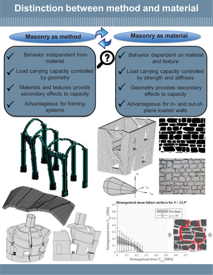
Fig. (1) highlights the distinction of masonry as a material and a method from a structural analysis standpoint. Masonry as material begins with the definition of the material and texture, and the behavior is dominated by strength and stiffness. Geometry plays a secondary role. Masonry as a method begins with and is controlled by geometry and form. Materials and textures are secondary.
1.1. Modernization of masonry
Recently, the argument has been made that curved masonry systems, such as the masonry arch, have the potential to be an advantageous structural framing system for modern constructions [66]. This is achieved through the isolation and optimization of the compressive and tensile systems and begins with the consideration of the compressive system.
Stability-Based Design (SBD) is defined as the stacking of units into stable configurations. This method describes the traditional approach of unreinforced masonry and represents an isolated compressive system. To successfully apply SBD techniques, however, the design must be updated to satisfy current safety and structural standards and be easily applicable by the practicing engineer. This can be achieved through the removal of sudden failure, the development of simplified engineering equations and procedures, and being economically competitive.
1.1.1. Removing Sudden Collapse
The removal of the sudden collapse has been proposed through Reinforced Stability-Based Design (RSBD) [66]. This RSBD technique maintains the traditional SBD behavior under normal service conditions and designs a reinforcement system that “activates” after the loss of stability. Failure is quantified by defining it as the loss of stability, and safety is added through the application of secondary reinforcement. The first mathematical investigation into this behavior produced a linear relationship between the applied load and mechanical hinge rotation for small angles. This linearity is carried into a linear strength problem through the application of a linearly elastic tensile material. The proposed methodology is achieved through the strategic application of reinforcement to remove the no-slip assumption, define the failure mechanism, and its resistance to motion.
The RSBD approach creates an efficient and accessible methodology to removing the conditions of slippage and sudden collapse. The application, however, only addresses the kinematically driven failure. What’s missing is an analysis structure that efficiently and effectively quantifies the system through the various stages of development and design.
1.2. Defined Failure of the Masonry Arch
The successful reintroduction of masonry framing as a modern construction technique requires efficient and accessible design methodologies derived around control and optimization. By separating the material from the method, an analysis structure can be developed that can be designed and optimized around geometry and form. This can be achieved by starting with SBD.
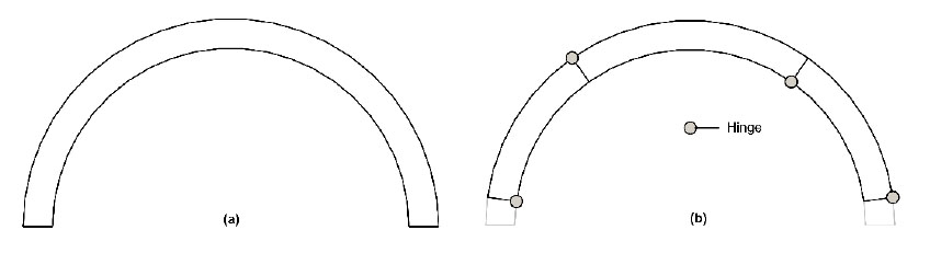
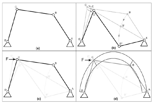
SBD analysis is a Boundary Value Problem (BVP) with a capacity defined by the onset of a mechanism. Mechanization is a physical phenomenon where a system transforms from a stable to a kinematic state. Fig. (2) shows the stable state and a kinematic state defined by the inclusion of four hinges for a masonry arch with a defined thickness. Traditional structural analysis and statics allow the four-pinned arch to be idealized into three pin-connected elements, as shown in Fig. (3a). This generates a condition with fewer reactive forces than Equations of Equilibrium (EOE) which results in collapse under self-weight (Fig. 3b). This collapse propagation, however, requires an oscillatory motion of element CD that can be resisted by the application of an external force, F (Fig. 3c). If the applied external force balances the effects of gravity imposed at point C by the unstable nature of point B, then the applied external force generates a kinematic state in equilibrium. Superimposing the pinned masonry arch with the defined thickness (Fig. 2b) to the idealized system (Fig. 3d) then demonstrates the arch's resistance to the failure motion under self-weight. Thus, the equilibrium condition of the idealized kinematic state is the transition point between the stable masonry arch and its four-pinned mechanical failure.
Unfortunately, the discussion provided to the engineering student is a statement of avoidance for any kinematic system in the evaluation of determinacy [67]. Thus, the idealized failure behavior of the arch is never considered, and the potential benefits are never realized.
1.3. Objectives
The objective of this work is to utilize the concept of masonry as a method to formulate an efficient and accessible structural analysis methodology and software that supports the reintroduction of curved masonry as a modern construction method. The foundation of this methodology is kinematic equilibrium. The blueprint is an analysis structure used for the formation of the software and the characterization strategies developed for first-order assessments and synchronization with experimental observations.
1.3.1. Kinematic Equilibrium
The static equilibrium analysis of a kinematic state superimposed on a stable condition through the incorporation of at least one external loading variable to the free-body diagram and corresponding equations of equilibrium that define the structure.
The novelty of this work is the establishment of a comprehensive analysis structure for masonry arches that is designed for the efficient and accessible control, management, and quantification of a defined failure condition. This work begins with the establishment of kinematic equilibrium, its application to masonry arches subjected to mechanical joint control, and its subsequent use in all the developed static and dynamic analysis procedures, methodologies, and software.
1.4. Outline
This paper is divided into four sections, beginning with the Introduction in Section 1. Section 2 presents the body of the work where the development strategy of the kinematic free-body diagrams (Section 2.1), the analysis structure (Section 2.2), and characterization strategies (Section 2.3) are presented. The analysis structure includes the development of the Kinematic Collapse Load Calculator (KCLC) software and its ability to incorporate multiple mechanisms, generic arches, and mechanical deformations (Section 2.2.2). The characterization strategies include a first-order assessment strategy termed Collapse Load Diagrams (CLD) (Section 2.3.1) and the ability to synchronize the analysis model to arches subjected to hinge-control (Section 2.3.2). Section 2.4 then expands the analysis to the kinematic state for 2D seismic modelling. Section 3 then presents a brief discussion on the results of this comprehensive analysis structure. Lastly, this work is concluded in Section 4.
2.1. Equilibrium Condition after the Activation of the Failure Mechanism. Concept of “Kinematic Equilibrium”
Assuming that a masonry arch is constituted by rigid blocks interacting with no-tension material interfaces, then classic limit analysis theorems can be applied. If sliding is precluded, then the collapse mechanism is activated by the formation of four flexural hinges. For this reason, the kinematic theorem is the most suited tool for structural analysis and design. At the collapse instant, the failure mechanism is triggered, and the structure roto-translates into blocks with a constant set of linear velocities and rotation rates. This is the reason why traditionally, the upper bound theorem is applied through the principle of virtual powers, which is extrapolated from the principle of virtual work used to analyze redundant systems under elastic modelling and beam theory. The equilibrium conditions after the activation of the failure mechanism still hold because the velocities and rotation rates are constant. It can be therefore stated that the equilibrium equations can be written at the incipient collapse state, suggesting a generalized concept of “kinematic equilibrium”, which directly focuses on the equilibrium requirements of the kinematic state. A stable system requires an external loading condition to form a kinematic system, and thus the two can be paired. The analysis can then be directly structured into a determinate equilibrium problem with no virtual conditions.
2.1.1. Equilibrium Problem
Statics states that a structure or its members are in equilibrium when the forces and moments are balanced. For principal load-carrying portions that lie on a single plane, the Equations of Equilibrium (EOE) are reduced to where ∑Fx and ∑Fy are the algebraic sums of the cartesian components of the forces and ∑MO is the sum of the moments about the point O.
 |
(1) |
For the traditional rigid-no-tension model of a masonry arch, the standard kinematically admissible mechanism requires the development of four hinges that alternate between the intrados and extrados (Fig. 2b). A hinge develops when the concentration of the normal forces near the intrados or extrados and can be idealized by concentrated point loads at the boundary. Assuming perfect hinges allows the kinematic arch to be expressed as three rigid pin connected elements, as shown in Fig. (4).
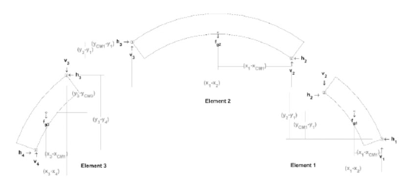
A pin connection between blocks removes the ability to carry a moment at the joint. Decomposing (Fig. 4) into the three rigid elements as seen in Fig. (5) allows the standard static equilibrium equations (i.e., Eq. (1)) to be constructed for the three-element systems. Note in Fig. (5) that the decomposition of the three rigid elements includes the lever arm distances used for calculating moments to satisfy Eq. (1).
The three-element representation of the arch generates nine equilibrium equations, but under its self-weight, only eight unknowns exist due to the pin connections. In the traditional sense of statics, this condition is unstable. A ninth variable is required to create a determinate system and with it, a single solution to the equilibrium problem. This ninth variable can either be a restriction of motion through the removal of a pin connection (i.e., the three-pinned arch) or the inclusion of an applied force that imposes equilibrium on the system.
It is important to note that a kinematic system at rest and in equilibrium is static. While this notion is unfavorable in the context of civil engineering, the unidirectional motion of the defined kinematic arch allows the condition to be specific to a single condition that can be controlled through design.
Assuming stability under self-weight, therefore, requires the application of an external load to generate a kinematic condition. Thus, the loading condition can be assigned a variable and incorporated into the EOE to construct a kinematically determinant system with a single solution.
In matrix form, the EOE can be expressed as
 |
(2) |
where BC is the balanced matrix, r is the reaction vector, and q is the constants vector. The addition of a loading condition and the accompanying loading variable into the formation of the EOE generates a non-zero determinant for BC, allowing the reaction variables to be obtained by
 |
(3) |
The EOE can thus be represented by a combination of a balanced matrix, reaction vector, and constants vector group required to solve Eq. (3).
2.1.2. Loading Conditions
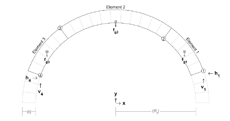
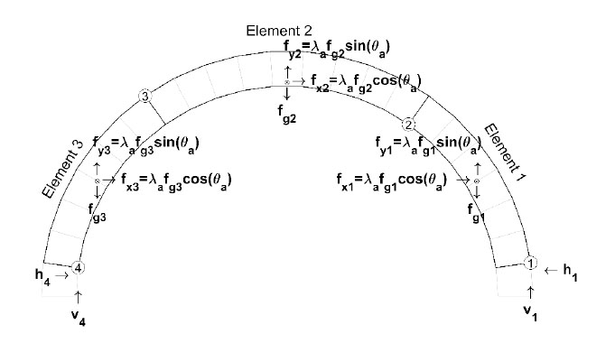
A loading condition variable is introduced to the EOE by adding a multiplier to the geometry of the applied condition. The choice of the multiplier depends on the conditions under evaluation. For seismic assessments, the multiplier, λa, is a factor of the gravitational constant g, which simplifies the body forces. Fig. (6) shows the free body diagram for a uniform acceleration applied to the four-pinned arch in Fig. (4). The uniform acceleration generates the EOE
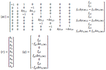 |
(4) |
In Eq. (4) vi and hi are the vertical and horizontal reactions at the ith hinge, respectively, and fgj is the body force of the jth element applied at the element’s center of mass. The moments were calculated by the cartesian forces multiplied by their respective vertical, Δy, and horizontal Δx, lever arms. The subscripts of, Δx, and Δy, denote the hinges or center of mass locations used to construct the lever arms and as shown in Fig. (5) (i.e., Δy2,1 is (y2 – y1) and Δx1,CM1 is (x1 – xCM1)). The acceleration vector is
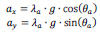 |
(5) |
where λa is the magnitude and θa is the polar angle of the acceleration. Note that either a direction or magnitude of the acceleration is required to maintain the linear set of equations. If the angle is defined, then the variable is λa. If λa is fixed, the evaluation can determine rotational collapse. This rotational collapse is useful for simplified seismic evaluations and experimentation (see Section 2.3.2.2).
2.1.2.1. Combining loads
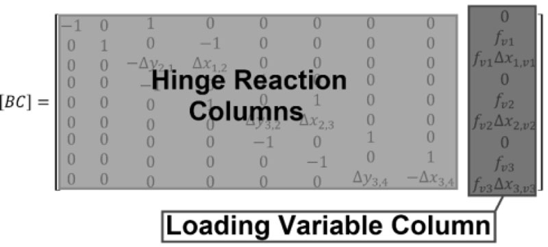
Eqs. (4 and 5) represent the equilibrium condition shown in Fig. (4). Different loading conditions require different EOE sets, but within the structure of BC, the effects of different loading variables are isolated in a single column, as highlighted in Fig. (7). This allows for a simple exchange between q and the load variable column of BC. This is important in the context of new construction as it identifies a simple methodology that can be utilized to establish a simple database structure for the required loading conditions that must be analyzed for limiting conditions and structural detailing.
2.1.2.2. Mechanisms
The four-pinned arch is the ideal failure mechanism and in the context of modernization is the failure to be engineered. There does exist the potential for other mechanisms. These can include slip joints and combined slip-hinge joints. These non-ideal conditions must be considered to ensure that the applied reinforcement to resist them is sufficient for the defined failure to control
The replacement of a hinge with a slip joint requires the added condition of static friction to the EOE. This is balanced by the inclusion of a moment into r. Therefore, each slip joint adds another equation and expands the EOE.
The inclusion of a combined hinge-slip joint requires an exchange with another hinge joint. This exchange is the result of releasing a second degree of freedom at a pin connection. Removing a pin reduces the number of elements and subsequently the EOE.
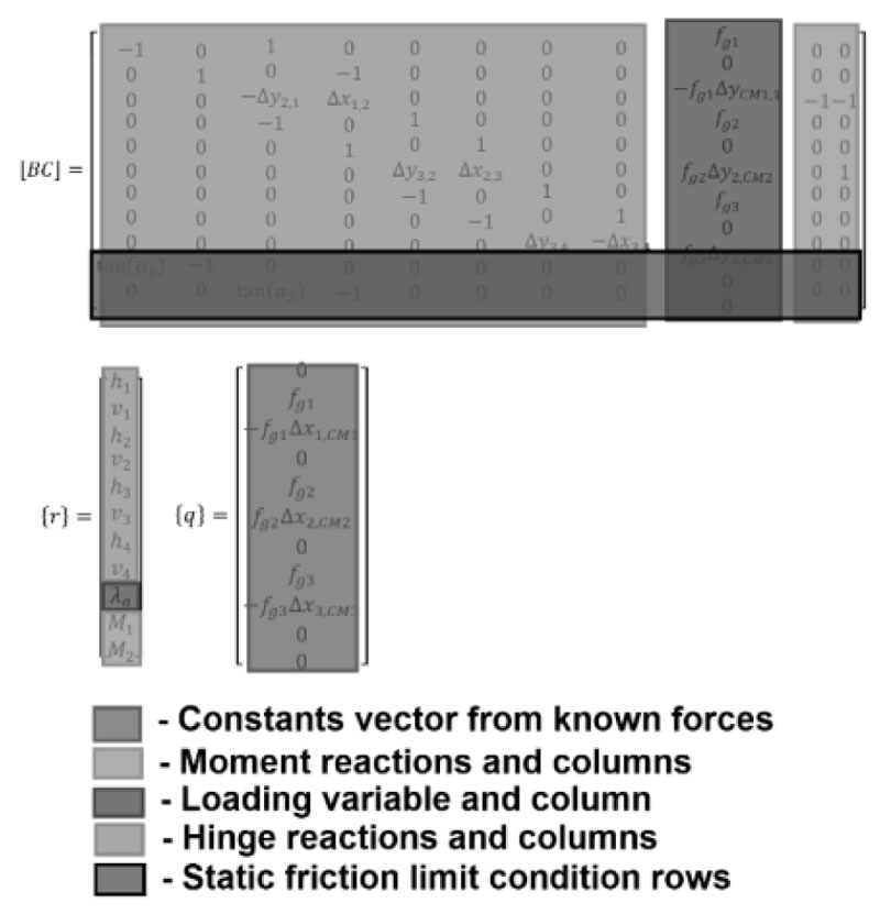
For a more detailed discussion, including the constructed free-body diagrams and EOEs for the different mechanisms, refer to the literature [68, 69]. What is important to consider is that the effects of the different motions are relatively isolated within the matrix structure of the EOE. This allows for the simplified matrix construction strategy (Fig. 8) for multi-mechanism analysis. This can also assist in the extension of the database structure beyond the loading conditions.
2.2. Black Box Analysis
The concept of masonry as a method revolves around the failure mechanism of a stable dry-stack masonry arch. This mechanism creation is a physical phenomenon and presents a singularity into a system that otherwise has infinite solutions. This singularity generates a black box condition to the input (loading condition and mechanical joints) and output (capacity and reactions) of the arch.
Kinematic equilibrium generates the EOE and Eq. (3) produces a solution set. The solution set, however, does not consider the validity of the results. They provide a link between the input and output, but the link itself must be evaluated to consider if it can physically exist. For instance, the failure motion of the pin-connected elements in Fig. (3b) cannot physically exist for the arch (Fig. 3d).
The potential solution set must abide by the limited rules of motion defined by the stable system. Therefore, the admissibility of the solution set must be evaluated.
The black box analysis is a direct reference to the evaluation of admissibility. The mechanization of the masonry arch requires a distinct set of conditions. These conditions are physical and do not require the application of engineering judgment. Therefore, they can be housed under a black box structure to simplify the approach. This expands the potential accessibility of the analysis model to technicians, architects, and other non-engineering staff involved in the design and construction of structures.
2.2.1. Kinematic Admissibility
The admissibility of a given loading-mechanism condition is subdivided into a two-stage evaluation. The first is a direct assessment of r. The four-hinged mechanism under uniform acceleration requires a positive λa and compressive forces at the hinges. The compressive force evaluation is achieved by comparing the net reaction force vector direction at each hinge with the boundary line of the mechanical joint.
The second stage of the analysis process is an evaluation of the thrust line geometry. The thrust line is a theoretical line that represents the flow of compressive forces. Stability requires this line to exist within the material geometry. For the admissibility of a defined kinematic condition, it only has to pass through the defined hinges.
2.2.1.1. Thrust Line
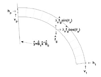
After obtaining the solution set to r, the thrust line can be established by evaluating the free-body diagram shown in Fig. (9). The thrust line is also the line of zero moment. Therefore, thrust points can be determined by calculating the point along each joint line (represented by the linear extension of the joint in Fig. (9) where the vertical, vP, and horizontal, hP, reactions maintain zero moment at hinge H1.
2.2.2. Kinematic Collapse Load Calculator
Both the kinematic EOE and the thrust line are geometrically dependent. The solution to Eq. (3) also requires the inverse matrix calculation of BC. These conditions are too labor-intensive to perform by hand, but modern computing power and drafting software make these conditions almost trivial and immediate. Thus, the creation of the KCLC [70].
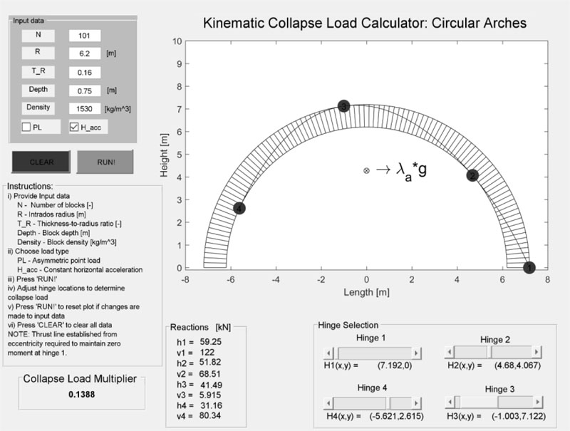
The KCLC is a stand-alone interactive calculator developed in MATLAB® to perform the black-box analysis of masonry arches. The original open-source KCLC utilizes the kinematic EOE and kinematic admissibility conditions to provide an analysis of user-defined circular arches subjected to either an asymmetric point load or constant horizontal acceleration. It allows the adjustment of the defined kinematic mechanism through hinge positioning; displays the arch, hinges, and loading condition; and calculates and displays the solution to r and the thrust line (Fig. 10). For each change in the hinge position, r and the thrust line are recalculated and displayed.
The original KCLC requires no direct understanding of the analysis, which enables it to become an effective educational tool for teaching the concepts of the kinematic theorem, the thrust line, and stability. Adaptations to the original software have also significantly broadened the conditions that can be analyzed. These expansions include additional mechanisms, generic arch geometries, localized capacity compensation requirements to establish traditionally non-stable but kinematically admissible conditions, and mechanical deformations.
2.2.2.1. KCLC and Multi-Mechanism Analysis
The first adaptations to the KCLC were implemented to address an experimentally observed non-traditional mechanism [71]. The observed mechanism replaced hinge H1 with a slip joint. Six additional mechanism types were incorporated into the software. The added mechanism types included the different combinations of slip joints, hinge joints, and combined slip-hinge joints, paired with the observed slip at H1. From the inclusion of the observed failure condition into the KCLC software: (1) a friction angle consistent with the block material was calculated for measured capacity of the arch; and (2) the observed mechanism was the limiting condition of the seven different mechanisms [69].
These added mechanism types are only a fraction of the possibilities. In total, there exists the potential of 70 different mechanism types [68]. It will be necessary to evaluate all the possible failure modes when designing an arch for civil applications, but the database structure of the EOE combined with the KCLC creates an incredibly efficient analysis, as shown with the inclusion of the seven [69].
2.2.2.2. KCLC and Generic Arches
Based upon the EOE, the information required to calculate capacity and admissibility through the black box analysis approach is the load geometry, arch block geometry, mechanical joint locations, and the centroid and magnitude of the mass of each block. Including uniform depth and density also allows the geometric pairing of the mass and area centroids. AutoCAD® thus provides the ideal tool to establish these geometric parameters. To utilize the drafting strength of AutoCAD®, an AutoLISP® script was created to extract the arch block geometry and centroid information and compile it into a text file to pass to MATLAB® [72, 73]. The script works by having a user identify the intrados and extrados block boundary points in the AutoCAD® file. The blocks are then counted, drawn, and the centroid data calculated. This efficiently links the design and structural analysis of any 2D arch-block geometry.
2.2.3. Capacity Compensation for Non-Stable Mechanisms
Kinematic admissibility only requires the boundary conditions of motion (i.e., hinge locations, mass distribution, and loading geometry). This allows the theoretical thrust line to exist outside the material between hinges. The laws governing forces disagree. For any kinematic condition to physically exist, the thrust line has to be adjusted back within the material boundary to maintain the assumption of rigid elements between mechanical joints. Theoretically, this is achieved by imposing an eccentric shift at each block joint where the thrust line lies outside the material boundary and balancing it with a required moment or opposing tensile force at the specified position. The thrust point positions calculated through the free-body diagrams for thrust point calculations (Section 2.2.1.1) establish a quantifiable condition for this eccentric shift. A more detailed description can be found in the literature [68, 69]. The importance here is that the minimum reinforcing capacity requirements necessary to define a particular mechanism can be efficiently quantified and incorporated into the KCLC. This will ultimately support the efficient detailing of the engineered system.
2.2.4. Mechanical Deformations
The final consideration of kinematic equilibrium is the actual mechanical deformations from the defined kinematic condition. An arch can be mechanically deformed and static. This deformation can arise from foundation settlements, finite reinforcement stiffness, and loading conditions that initiate mechanization but do not drive it to collapse. Each of these results in changes to the boundary conditions, but kinematic equilibrium and admissibility still hold. The ability to impose these deformations is therefore necessary.
The kinematic condition of a dry-stack masonry arch is a Single Degree of Freedom (SDOF) problem. The SDOF is confined to the mechanical joints. In the context of design, the mechanism is engineered through reinforcing against non-ideal mechanisms (Section 2.2.2.1) and any capacity compensation requirements (Section 2.2.3).
2.2.4.1. Mechanism Motion
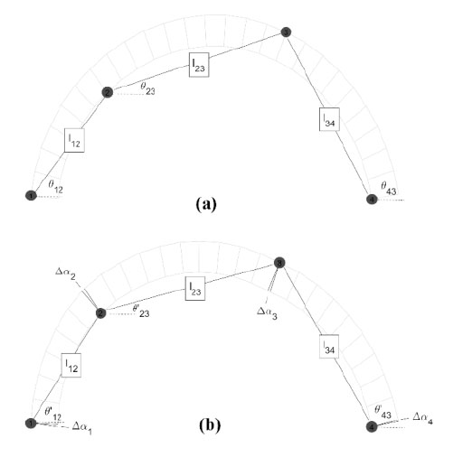
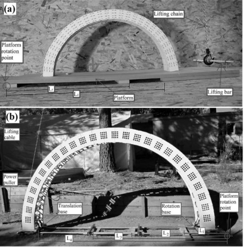
To examine experimentally observed static SDOF deformations, a simplified KCLC was constructed [69, 71]. SDOF motion requires the definition of one degree of motion to express the total deformation of the system. In the context of a dry-stack arch with defined mechanical hinge joints, the arch-hinge configuration is represented by three fixed lengths, lij, connected by four pins at the hinge locations (Fig. 11). The SDOF that binds the motion is the horizontal displacements of hinges H2 and H3. Hinges H1 and H4 are translationally fixed to their respective bases and thus limited to rotations. For a given rotation, Δα1, at hinge H1 the rotation of hinge H4 can be expressed by Eq. (6) through the application of the law of cosines. The lengths, lij, and angles, θjk, are identified in Fig. (11). The translations of hinges H2 and H3 can then be determined through the application of the rotation displacements, Δα1 and Δα4, and lengths l12 and l34, respectively. Lastly, the polar rotation of the H2-H3 connection can be determined through the comparison of the initial and final states. This polar change provides the additional rotation to define the intermittent hinges’ deformations.
Applying these mechanical deformations to an arch and reapplying the kinematic EOE in the KCLC structure reveal (1) that static-deformed conditions still require external loading to exist; (2) that the deformation path within a kinematically admissible range of motion can be defined to single-point translation and lever arm rotations; and (3) the evaluation of capacity compensation with the deformations can generate the ability to directly calculate experimentally observed finite hinge stiffness of reinforced joints [74].
This extends the theoretical foundation of the method of masonry to the deformation of the defined condition. The KCLC, though, is only a calculator. It does not provide a strategy or engineering judgement.
 |
(6) |
2.3. Characterization of Dry Stack Arches
The kinematic EOE and their application to the structural analysis of dry dry-stack masonry arches through the condition of admissibility and the black box analysis approach have demonstrated a simple analysis methodology. With the aid of the KCLC, any defined condition of dry-stack masonry arches becomes accessible. What is lacking is the characterization of the element itself. Given an arch, how does it behave when subjected to hinge control; how can arch geometry and reinforcement be optimized; and how can the theoretical analysis link with experimentation?
2.3.1. Collapse Load Diagrams
First-order strategies of assessment exist for most modern structural systems. These first-order assessments provide the platform for a project’s planning, development, scope, cost estimates, and allocation of funds. They are a critical component to the successful implementation of any modern structural system. For civil projects, these first-order assessments can often be carried beyond the 60% design stage. For existing systems, first-order assessment strategies streamline inspections and interventions, and their efficiency becomes critical in post-disaster situations.
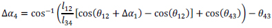
Collapse Load Diagrams (CLD) are a first-order assessment strategy formulated for masonry by combining a set of capacity results with a single parameter [75]. The single parameter for the arch is the polar angle between the base hinges H1 and H4 taken from the intersection of the arche’s base and midspan. The capacity results present the set of minimum collapse loads for all admissible combinations of the base hinges. Plotting these capacities against the negative tangent of the polar angle between the base hinges generates the CLD.
The diagrams are created by fixing the base hinges and determining the minimum positive collapse multiplier for the admissible variations of hinges H2 and H3 using the same EOE with updated boundary conditions to account for the change in hinge position. The minimum multiplier and the associated hinge positions are recorded, one base hinge position is changed, and the new minimum multiplier is determined. This is repeated until all admissible base hinge configurations have been exhausted. These values are plotted, and lines are drawn connecting the multipliers associated with one of the two base hinges remaining fixed.
Fig. (12) shows a CLD and arch geometry for a 27-block semi-circular arch subjected to a constant horizontal acceleration. The CLD is accompanied by a subplot of the arch-load geometry, which also identifies the limits of admissible base hinge positions. This provides not only the capacity values but a quick visualization of where the base hinges can be defined in the development of a hinge-controlled arch system. The CLD thus provides the types of capacity values and required base reinforcement criteria ideal for sizing an arch and shaping its mechanism in the preliminary design stages of a project. The KCLC would then be available for the detailing of the selected arch as they both utilize the same foundational EOE.
2.3.2. Tilt Test Characterization
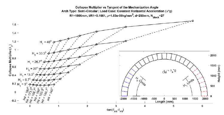
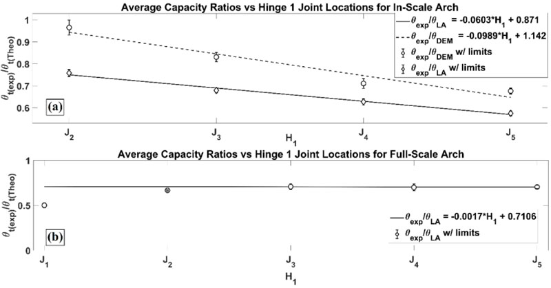
A notable characteristic of the CLDs is that hinge H1 dominates capacity. The effects of hinge H4 are secondary to H1. This unique relationship allows the capacity behavior to be formulated into a single variable approximation (i.e., hinge H1’s position). This key variable, in combination with experimental capacity measurements of a family of mechanisms, generates a simplified link between a physical arch and its theoretical model. In other words, the arch can be characterized To test this characterization potential, two experimental arches subjected to hinge control were constructed [71, 76]. Both arches were semi-circular with 27 blocks (Fig. 13). The first arch (Fig. 13a) was an in-scale arch and had a clear span of 0.67 m. It was constructed from timber blocks with Velcro® providing reinforcement for the non-mechanical joints. The mechanical joints were defined by the lack of reinforcement. The second arch (Fig. 13b) was a full-scale arch with a clear span of 3.84 m. The blocks were engineered from the oriented standard board for the block faces and steel risers for the out-of-plane thickness. 36-grit sandpaper was added to the joint faces to increase the friction angle between blocks, and cam straps were the reinforcing material for establishing hinge control.
For each arch, 25 distinct hinge sets were tested with three measured failures per set. The failure capacities of each set were averaged and compared against the theoretical values. Then the hinge set capacities, both theoretical and experimental, were averaged for fixed H1 positions and then compared again through normalization. From this comparison, a single linear capacity adjustment equation was established for each arch that adjusts the theoretical capacities to the experimental. Fig. (14) shows the capacity adjustment equations for both arches. For the in-scale arch, a DEM analysis was also performed, and a linear capacity adjustment equation was also established (Fig. 14a) [69]. This equation differs from the kinematic equilibrium approach, but a single adjustment equation is established, which highlights the versatility of this characterization approach. For the full-scale arch, there were some observed anchorage issues between the arch and the tilting platform [76]. This was adjusted, and the linear equation was obtained from the final three positions of H1 (Fig. 14b).
Note that Eq. (5) was restructured such that the rotation angle was the collapse load variable. The actual block measurements were used to draw the model arch in AutoCAD® and then extracted for the arch analysis model. Also, a CLD was created for each arch to establish the hinge sets tested and theoretical capacities. Refer to the literature for a full description of the experimental campaigns [68, 71, 76]. The key here is that the hinge-controlling of dry-stack arches and the examination of a family of admissible mechanisms allows for the direct characterization of the analysis model to the actual arch. This significance is further entrenched by the lack of damage observed to the arch. This generates the potential to establish individual capacity ratings for constructed arches.
2.4. Dynamic Modelling
Any modern comprehensive analysis model must be able to address dynamic conditions. Kinematic equilibrium identifies the transition point between the stable and kinematic systems. This holds as long as a kinematically admissible condition exists, and along with the SDOF motion, generates a deformation-capacity profile: the capacity being the applied force to maintain the system in a kinematic state. The applied force coupled with a deformation path generates the required work, Wreq, necessary to change positions. Assuming conservative work and utilizing its path independence allows the change in kinetic energy, ΔKE, to be determined by
 |
(7) |
Where the applied work, Wapp, is based upon the motion of the loading condition. The SDOF motion also allows the restructuring of the velocity form of kinetic energy
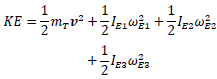 |
(8) |
such that the center of mass, mT, translation with velocity vector, v and element-based lever arm inertias, IEj with their angular velocities ωEj can all be expressed in terms of a single variable. The spatial and time components can then be isolated to create a single variable integral for a fixed time step. Defining the variable as the horizontal position, x, of the centroid of the mechanical arch then provides the methodology to establish a dynamic time incremental analysis. This was first achieved for the constant horizontal condition and then generalizes through Eqs. (4 and 5) into accepting 2D acceleration profiles [77, 78].
This time incremental analysis works by applying fixed accelerations per timestep. Then the final position and kinetic energy of the time step can be determined and set as the initial conditions of the next time step and so on. This propagation continues to the end of the applied sequence or when the deformation extends beyond the limits of kinematic admissibility. The application of masonry as a method is thus extended to the dynamic condition.
Another important consideration is that the material properties of the blocks have not yet been defined. This, combined with the time incremental structure, allows the isolation of the impact if the arch returns to the original configuration. The coefficient of restitution (COR) can then be directly applied to impact. The COR defines the energy loss of the impact itself and can be directly applied to the existing kinetic energy at the timestep of impact. A COR of one and zero represents perfect elasticity and plasticity, respectively.
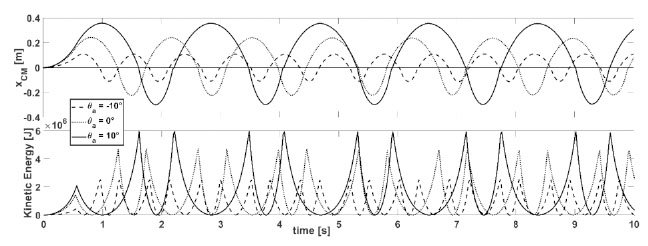
While no direct experimental testing on the dynamic behavior of hinge-controlled masonry arches has been performed, conservation of energy tests (i.e., COR = 1) was performed. Fig. (15) shows the displacement and kinetic energy versus time for the conservation of energy tests where a 0.55 g magnitude acceleration was applied for 0.5 seconds at different vector angles. These results revealed negligible energy loss after 20 seconds of free motion [78].
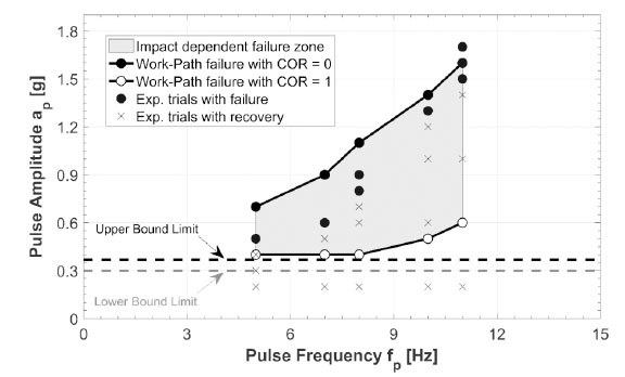
Additionally, the dynamic modelling approach was compared against the experimental sign pulse testing found in the literature on a non-hinge-controlled arch [79]. A collapse envelope was established between perfect elasticity and plasticity of the theoretical model for the different pulse frequencies and amplitudes tested (Fig. 16) The results of the comparison revealed that the measured failures all fall within the envelope [77, 79].
3. RESULTS AND DISCUSSION
The direct consideration of masonry as a method and the mechanical nature of its failure has generated the comprehensive analysis structure described in Section 2. Everything presented was constructed from the same underlying principles, the EOE, and evaluations of the solutions to the geometry of the arch being analyzed. The credit for this robust analysis structure lies in the transformation from the static to the kinematic state of the system. In physics, it is taught that to measure is to destroy, and in this instance, destruction belongs to the stable condition. Thus, generating a moment of existence where the state of the system is known.
Expanding the evaluation of statics to include a kinematic state at rest and in equilibrium then allows the direct calculation of the failure condition. These calculations are simple and instantaneous with the use of modern computing technologies. The interactive nature of the KCLC and incorporation of modern drafting software also extend the accessibility of the approach.
Lastly, the first experimental tests of controlling the failure method identified a methodology that allows the synchronization of the theoretical model with a physical arch through a linear characterization equation. Together with the KCLC and drafting software, this creates the potential for a single analysis structure to be used and expanded by designers, engineers, and researchers.
This work has presented the argument with substantial evidence and justification that a simple and efficient analysis model exists to support the application of masonry arches to new constructions. While not complete in the considerations of load cases, detailing, and the effects of material properties, it has addressed the fundamental issues preventing the reintroduction of masonry framing.
This great potential is also burdened by a need to educate and train architects, engineers, technicians, and contractors to have any chance of success, all of whom must be able to bid and build masonry framing systems. Therefore, the result of this work was the creation of Masonry Methods, Inc., whose mission is to promote and advance the application of masonry as a method [80].
CONCLUSION
Masonry has a great potential to be an advantageous method of modern structural design, but the concepts of masonry, the material, and the method must be disentangled. The breadth of work presented here identifies the need to establish the concept of masonry as a method and formulates the foundation necessary to perform the comprehensive analyses that are required by modern structural analysis.
Kinematic equilibrium incorporates a force-mechanism pair into the standard free-body diagrams and EOE used in statics. This creates a database structure to the kinematic EOE for the variations in force-mechanism pairs.
This database structure is combined with user-defined arches to construct a simple analysis that evaluates the admissibility of the combined system for any drawn arch. The KCLC software provides the black box analysis structure such that a defined condition does not require the explicit understanding by the user: a typical case for a calculator or voltage regulator. Therefore, the complexities of the masonry arch analysis can be isolated from the practitioner during structural design.
Lastly, characterization strategies demonstrate masonry as a method’s adaptability and its ability to incorporate all aspects of structural analysis. This is accomplished through the analysis of a family of mechanisms for a given arch and through the expansion of the analysis structure into dynamic modelling.
3.1. Future Developments
As mentioned in Section 3, Masonry Methods, Inc. has been created to champion the reintroduction of masonry framing for modern constructions. The current and future work being performed is the creation of practical stand-alone masonry framing systems developed from engineered blocks, the continued advancement of the supporting analysis software, and the expansion of the analysis structure to three-dimensional systems.
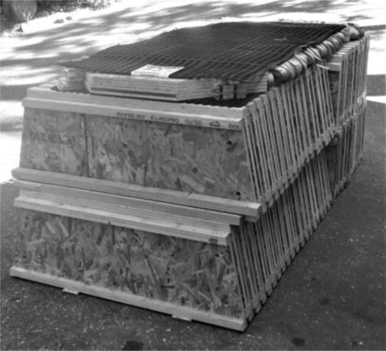
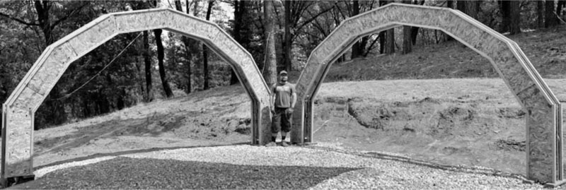
The current stand-alone project is the construction of a cross vault frame developed from engineered blocks. Thus far, the materials have been prepared for the blocks, as seen in Fig. (17), and construction has begun with the assembly of the first two arches (Fig. 18).
LIST OF ABBREVIATIONS
| ax | = Horizontal acceleration |
| ay | = Vertical acceleration |
| [BC] | = Balance matrix of the equations of equilibrium |
| BVP | = Boundary Value Problem |
| CMj | = Centre of Mass of the jth element |
| CLD | = Collapse Load Diagram |
| COR | = Coefficient of Restitution |
| EOE | = Equations of Equlibrium |
| fgj | = Gravitational force of the jth element |
| g | = Gravitational acceleration constant |
| Hi | = Identifier for the ith hinge |
| hi | = Horizontal reaction force at the ith hinge |
| hP | = Horizontal thrust point reaction |
| IEj | = Inertia between centre of mass and the jth element |
| KCLC | = Kinematic Collapse Load Calculator |
| KE | = Kinetic Energy |
| LA | = Limit Analysis |
| mT | = Total mass of the mechanical arch |
| {q} | = Constants vector of the equations of equilibrium |
| RSBD | = Reinforced Stability-based Design |
| RTN | = Rigid-no-tension Model |
| {r} | = Reactions vector of the equations of equilibrium |
| SBD | = Stability-Based Design |
| SDOF | = Single Degree Of Freedom |
| v | = Velocity vector |
| vi | = Vertical reaction force at the ith hinge |
| vP | = Vertical thrust point reaction |
| αi | = Rotation angle of the ith mechanical joint |
| Δxij | = j Horizontal lever arm between points i and j |
| Δyij | = j Vertical lever arm between points i and j |
| λa | = Collapse multiplier for uniform acceleration |
| θa | = Polar angle of acceleration |
| ωEj | = Lever arm angular velocity of the jth element |
CONSENT FOR PUBLICATION
Not applicable.
AVAILABILITY OF DATA AND MATERIALS
All data supporting this article can be found within the article and its references.
FUNDING
None.
CONFLICT OF INTEREST
The authors declare no conflict of interest, financial or otherwise.
ACKNOWLEDGEMENTS
Declared none.

