All published articles of this journal are available on ScienceDirect.

Novel Design Proposal for the Seismic Retrofit of Existing Buildings with Hybrid Steel Exoskeletons and Base Sliding Devices
Abstract
Background:
Existing Reinforced Concrete (RC) structures and brittle buildings are often exposed to seismic events that may have significant resistance and displacement demand compared to their actual capacity. Accordingly, an optimal retrofit intervention can ensure enhanced and safe structural performances for them. Among the techniques that have been addressed for the retrofit of existing RC frames, steel exoskeletons can notoriously improve the seismic performance of existing buildings due to their input stiffness, ductility and resistance. In this paper, the attention is focused on the interaction of steel exoskeletons with RC frames and the consequent details to achieve a more effective design of the retrofit intervention.
Objective:
Based on parametric calculations, a new hybrid design concept that takes advantage of traditional steel exoskeletons with additional base sliding devices (at the foundation level of the RC frame to retrofit) is addressed in this paper.
Methods:
As shown through SDOF and 2D-MDOF calculations, the definition of the optimal operational conditions (and thus mechanical configurations) for the so-assembled hybrid solution can maximize the potential of the retrofit intervention, with marked benefits in terms of ductility, resistance, and overall efficiency, ensuring very low damage in the existing building.
Results:
Given that the used base sliders are bidirectional, it is expected that the proposed solution could be efficiently extended to 3D structures, once the exoskeleton systems are optimally designed along the two principal directions of the hybrid structure to retrofit.
Conclusion:
The potential of the hybrid approach is shown based on parametric analyses. Furthermore, general design recommendations are proposed for the hybrid solution.
1. INTRODUCTION
Existing Reinforced Concrete (RC) structures and brittle buildings, as known, are often required to withstand seismic events that may be significantly high in magnitude (and thus require high resistance / displacement demand), compared to their actual capacity. Accordingly, an optimal retrofit intervention can ensure enhanced structural performance [1, 2].
In this regard, many research studies have been dedicated to several techniques that may be suitable for different existing structures [3-7], and especially for RC buildings [8-10]. The solutions with masonry infill walls [8] and with BRBs applied directly to the RC frame [9] are, for sure, very invasive. The building needs to be totally emptied in order to retrofit it, with the consequent need to relocate the occupants. A simplified design method has been proposed [11] for the use of diagrid exoskeletons in RC frames. The use of diagrid exoskeletons allows retrofitting the buildings by working from outside, without relocating occupants, but the exoskeleton is meant to remain elastic and it creates a very stiff structure that can cause high seismic actions on the retrofitted building. It should be coupled with a dissipative system at the connections to the RC frame.
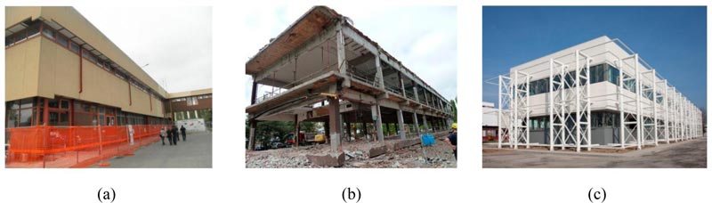
Among others, one of the recent trends involves the use of external steel bracing systems (“exoskeletons”) that are intended to act as exoskeletons for the RC members [12, 13]. In a study [13], the effects of the retrofit are investigated with a simplified model based on two coupled linear viscoelastic oscillators. Based on the “traditional” design concept of these exoskeletons, the optimal seismic retrofit of a given existing RC building derives from the mechanical interaction of weak and brittle RC members (through suitable links at the level of each floor) with a steel bracing system. The bracing system is typically characterized by high resistance, ductility and high dissipative capacity, which lead to the realization of a seismic efficient, hybrid steel-RC structure [14-17] and (Fig. 1).
The main goal of traditional exoskeletons, in other words, is to transfer the seismic demand from the brittle components (existing building) to the ductile members (steel bracing system). Many design input parameters can be responsible for marked variations in the final seismic response of a given steel-RC hybrid system. Due to the specific features of the RC building itself (element dimensions, rebars, geometry and masses) and the characteristics of the steel system (stiffness, stiffness ratio between storeys, type of diagonals, resistance), the behaviour of the hybrid system can vary markedly. As a general rule, the steel exoskeleton is designed to remain linear elastic under the input seismic events [12, 13]. In some cases, vicious or other dissipative connections (i.e., seismic devices based on shape-memory alloys or viscous devices) are interposed between the exoskeleton and the primary building to retrofit [14, 18].
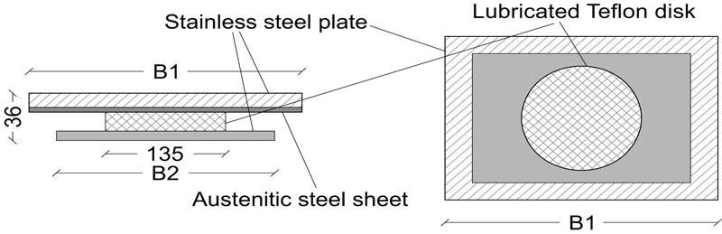
In this paper, the attention is focused on the definition of the models to use for the study and then on the design of the key parameters of the steel exoskeletons, namely resistance and stiffness, compared to the original parameters of the RC building (Section 2). The aim is to investigate how the response of the hybrid RC-steel system changes based on the variation of the characteristics of the exoskeleton. For this purpose, a Single Degree of Freedom (SDOF) model is first analysed. Based on a parametric study, some limit conditions are explored. The seismic response of a given RC frame, coupled with a steel structure is analysed, considering high/weak stiffness and different resistance of the bracing system. In particular, the in-plane seismic response of such a relatively simple mechanical model is examined and the analysis is separately conducted on (i) the RC building, (ii) the steel exoskeleton and (iii) the hybrid steel-RC assembly, where the RC building is not isolated. Although the steel braces have an intrinsic ductility, it is shown (Section 3) that in general, an over-design in resistance or in stiffness of the exoskeleton can maximize the expected performances of the original building, but the brittle collapse of the RC structure can be hardly avoided, especially when the RC building is fix-based. For this reason, an additional option has been carefully considered: a novel hybrid solution that combines the traditional steel exoskeletons with a sliding system composed of planar steel-PTFE (Teflon) bearings (Fig. 2). This sliding system is simple, not expensive and insensitive to variations in the frequency content of seismic excitations [19-22]. The PTFE devices are placed at the base (or in the middle of the base columns) of the existing RC building to uncouple its motion from the ground motion and transfer all the seismic load to the steel exoskeleton, maximizing its efficiency and making the original building weakly stressed.
In such a way, the obtained hybrid system can efficiently withstand the assigned seismic loads, and the seismic demand can be efficiently transferred to the steel exoskeleton, protecting the RC building.
In support of these outcomes, the same design concept is also applied to a multi-storey RC frame (Section 4). As shown, the design benefit can be found at different levels. As desired, the RC building can mostly behave like an isolated system under a general seismic event. At the same time, the steel exoskeleton itself can be optimally designed for the expected seismic loads, exploiting at best its resistance, ductility and dissipation capacities. The final hybrid assembly can thus minimize the magnitude and distribution of residual damage in the existing building and not just prevent its collapse. In this research paper, the sensitivity of the exoskeleton design concept to its key input parameters is emphasized, with the support of theoretical and numerical analyses.
2. MATERIALS AND METHODS
2.1. Parametric Investigation
2.1.1. Reference Structural System
The parametric analysis is carried out on an existing RC frame that works in parallel with a steel exoskeleton system as in Fig. (3), based on an equivalent Single Degree of Freedom (SDOF) system representative of their key mechanical features. The steel exoskeleton is taken into account in the form of a rigid cantilever that is connected at the base through a nonlinear rotational spring (with initial stiffness K1, plastic resistance M1 and ductility μ1, see the “spring #1” in Fig. (4a)). The RC building, at the same time, is schematized in Fig. (3) through three rigid bars that are connected by nonlinear springs (“spring #2” type in Fig. (4b)) with initial rotational stiffness K2/2 and yielding bending resistance M2/2.
According to Fig. (4b), the nonlinear behaviour is characterized by limited ductility μ2 of springs, as it is typical of existing RC structures, and by a brittle collapse mechanism.
Until the springs are linear elastic, their constitutive law is given by:
 |
(1) |
Where Ki and φi are the rotational stiffness and the rotation of each spring in Fig. (3) (i= 1, 2). The shear force sustained by each building component can be expressed as a function of the displacement δ:
 |
(2) |
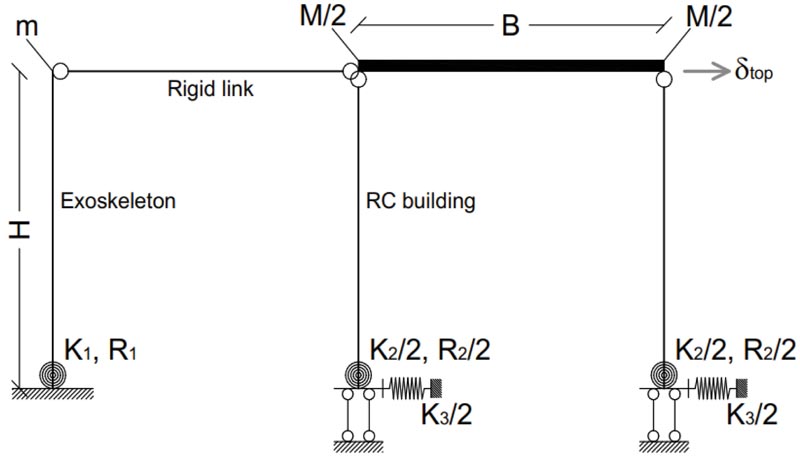
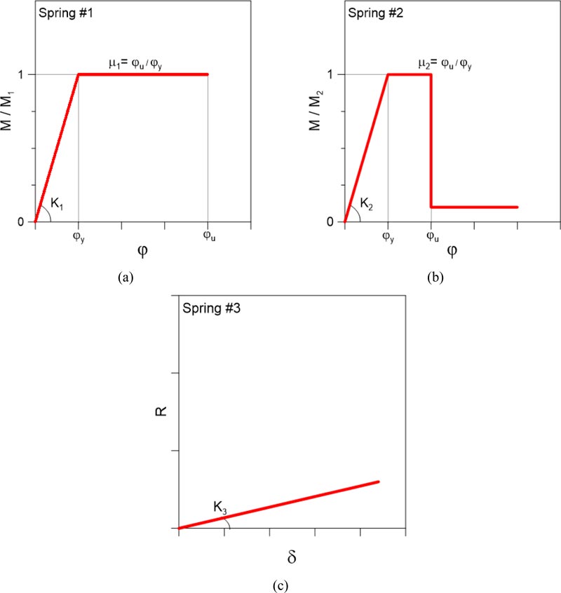
At the foundation level, the RC frame is equipped with a rigid restraint against possible rotations and vertical displace- ments. Two additional translational springs, characterized by a linear elastic behaviour (“spring #.3” in Fig. (4c)), are introduced at the base of the building to represent the level of connection of the building to the floor. The stiffness of these springs can vary from K3 → 0 (to represent a base isolation system) to K3→∞ (to represent a traditional non-isolated rigid foundation). The total mass is set as m and M for the exoskeleton structure and the RC frame, respectively. A fixed link is finally used to provide the mechanical interaction of the RC building and the exoskeleton under seismic loads.
In accordance with Fig. (4), the steel exoskeleton is expected to offer a certain resistance M1 and a relatively high ductility μ1 (up to ≈4-5). Such a retrofit contribution takes place in the RC frame building characterized by a given resistance M2, limited ductility μ2 (in the order of ≈1-1.5) and a brittle collapse mechanism, with very low residual resistances.
For an optimal seismic retrofit of the building, and thus maximization of the efficiency of the exoskeleton, it is usually expected that the ductility μ1 of the steel structure is fully exploited by the hybrid structure. The latter one should result in a structure with enhanced ductility and dissipative capacity, compared to the initial existing RC frame, and thus have an improved capacity to withstand the imposed seismic loads.
2.1.2. Seismic Design
From a seismic design point of view, the key dynamic parameters to account for the definition of input seismic loads are represented by the mass and stiffness of the structural components. These parameters also define the fundamental vibration period of structures: T2 for the RC frame, T1 for the independent steel exoskeleton and TTOT for the hybrid system in which the steel bracing members fully interact with the RC building.
In the design of the retrofit intervention, TTOT is thus responsible for possible variations in the seismic demand. The acceleration affecting the hybrid structure could be strongly sensitive to stiffness modifications and thus, the variation of TTOT could even increase the seismic demand.
Concerning the structural capacity, such a hybrid system can take advantage of any plastic dissipation in the structural members that is conventionally accounted for the well-known behavior factor. In this research study, it is assumed that q2≅ μ2≈ 1-1.5 is the initial behaviour factor for the un-retrofitted RC frame (given that in many cases, the existing RC structures only resist vertical loads), q1>>q2 is the behaviour factor of the steel structure alone and qTOT denotes the dissipation capacity of the hybrid assembly. The retrofit intervention is optimized when qTOT is much higher than q2.
2.1.3. Modelling
In order to explore the seismic efficiency of steel exoskeletons for the retrofit of the RC building prototype shown in Fig. (3), an analytical calculation was first carried out by varying the key input parameters earlier described (Fig. 4).
Selected SDOF configurations were further assessed with the support of nonlinear static analyses (cyclic push-over analyses), that were carried out in SAP2000 [23] to validate the simplified results. For these analyses, a cyclic in-plane lateral displacement δ was imposed at the top of the frame, whilst monitoring the corresponding deformations and reactions in each assembly component.
2.1.4. Definition of Limit Configurations
Among the possible combinations for the mechanical parameters in Fig. (4), the attention of this paper is focused on some limit configurations for the examined system, represented by:
- BLD: un-retrofitted building, with K2 the stiffness, M2 the resistance and μ2=2 its ductility; and a series of retrofit configurations that were implemented for the BLD model, that is with the additional contribution of a steel exoskeleton (with K1, M1 and μ1 the stiffness, resistance and ductility respectively). In accordance with Table 1, some reference limit configurations were selected from the parametric study, namely characterized as:
- EXO-1: non-isolated building, with an exoskeleton less rigid but much more resistant than the building (and thus elastic, under the seismic response of the RC frame);
- EXO-2: non-isolated building, with an exoskeleton much more rigid but less resistant than the RC building (0.75 the selected ratio);
- EXO-3: hybrid RC-steel system with an additional coupled sliding system, where the steel exoskeleton has a given stiffness K1, high resistance M1, and ductility μ1 (to define based on the input seismic design loads, independently from the RC building mechanical characteristics). The additional advantage is represented by the introduction of a series of sliding devices at the base (or at the level of the 1st floor, in case of multi-storey buildings) of the RC columns, in order to achieve a coupled sliding-hybrid solution that can maximize the potential and benefits due to the steel exoskeleton.
3. RESULTS AND DISCUSSION
The analysis of the parametric results is focused on the typical base-shear R / top displacement δ response of the systems in Table 1, in order to assess their global in-plane lateral response.
For the sake of clarity of the presentation, all the parametric estimates are proposed in non-dimensional form, as a function of the measured base shear R (compared to the RC frame shear resistance, R2) at any instant of the analysis (Eq.(2)), and the corresponding top displacement δ of each building component. The latter is presented as a function of the lateral displacement leading the RC columns to the first yielding configuration, δy,2. The attention is thus focused on the response of the RC frame, the steel exoskeleton and the hybrid system.
3.1. BLD System
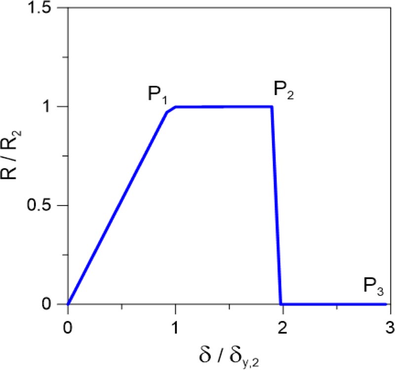
In Fig. (5), the typical brittle response of the BLD system is proposed. Until the yielding configuration is achieved (P1), the plot evidences a linear elastic response in the initial stage of the seismic event. The plastic response, and thus the overall ductility of the BLD structure, is relatively small, and the brittle collapse mechanism initiates at point P2 and has the null residual capacity (P3).
| - |
Exoskeleton Spring #1 |
Base-isolation System Spring #3 |
||
|---|---|---|---|---|
| - | K1 / K2 | M1 / M2 | μ1 / μ2 | K3 |
| BLD | - | - | 2 | - |
| EXO-1 | 0.5 | 1.5 | 7 | ∞ |
| EXO-2 | 10 | 0.75 | 7 | ∞ |
| EXO-3 | 1 | 1.20 | 7 | 0 |
3.2. EXO-1 Solution
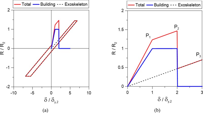
The EXO-1 solution is analysed in Fig. (6), where both the cyclic and detail responses are emphasized for the RC building, the exoskeleton and the total hybrid assembly, respectively. The EXO-1 solution, in particular, represents the typical application of a steel bracing system that is expected to optimally react to the input seismic loads, given its limited (and thus positive) stiffness K1 and relatively high resistance (R1/R2= 1.5), with large ductility (μ1/μ2= 5).
As shown in Fig. (6), however, major limits towards the potential benefits of such an exoskeleton are represented by the limited stiffness itself, compared to the original building. The stiffness of the exoskeleton alone can be clearly perceived from the 0-P3 segment in Fig. (6b). As such, a direct effect is that the original stiffness of the BLD system is only minimally increased by the collaborating steel exoskeleton. This effect can be perceived from the segment 0-P1 in Fig. (6b), where:
 |
(3) |
and
 |
(4) |
is the maximum resistance that can be achieved.
The steel structure, due to the relatively low stiffness but high resistance, can sustain part of the input seismic loads, as shown by the segment P1-P2 in Fig. (6b). Key mechanical parameters are, in this case, the stiffness that can be expected from the hybrid system:
 |
(5) |
and the maximum resistance:
 |
(6) |
A strong dissipative contribution would also be expected from the exoskeleton itself (Fig. 6a). Due to the limited stiffness, however, the potential plastic deformations and dissipative phenomena of the steel bracing system are activated only once the BLD structure is already collapsed. Even in the presence of residual stiffness and high ultimate resistance for the steel structure (P3), the latter is not able to preserve the RC frame from a brittle collapse mechanism. Accordingly, the third stage of the overall seismic response in Fig. (6b) starts at a lateral displacement:
 |
(7) |
and is characterized by a total stiffness that still equals the exoskeleton alone (Eq.(5).
From a seismic design point of view, the EXO-1 retrofit intervention is thus not successful, and the hybrid assembly is still strongly sensitive to the initial BLD features. Accordingly, the reference behaviour factor qTOT for the seismic design of the hybrid structure is still represented by the RC building one (qTOT = q2). On the other hand, the increased initial stiffness of the hybrid assembly is associated with a reduction in the period of vibration of the system, TTOT, thus increased input seismic loads.
3.3. EXO-2 Solution
In this system, markedly high stiffness and a moderate resistance are assigned to the steel exoskeleton. The achieved seismic response for the EXO-2 assembly is shown in Fig. (7).
Compared to the original BLD system, it is possible to perceive that the hybrid solution can take substantial benefit of the exoskeleton features, thus achieving a relatively higher stiffness (segment 0-P1 in Fig. (7b)) and maximum resistance (R/R2 ≈1.75), where:
 |
(8) |
As far as the comparative data in Fig. (7) are taken into account,, it is possible to see that the final result does not always preserve the RC building from a potential brittle collapse, thus waning the benefits due to the elasto-plastic steel members.

In order to ensure optimal efficiency of the retrofit intervention, the exoskeleton itself must be over-designed, both for stiffness (K1) and resistance (R1) parameters. The resistance itself, accordingly, should be generally defined by taking into account a conservative input seismic load for design, and thus minimizing the potential risk of exoskeleton collapse. In Fig. (7), it is in fact possible to notice that the RC frame takes advantage of the additional stiffness (segment 0-P1, Eq.(3)) of the steel members alone (0-P0). From P0, the steel structure starts to dissipate part of the incoming energy through plastic deformations in support of the RC frame that has already achieved the yielding configuration (Eq.6) up to its maximum resistance capacity (Eq.8).
As it can be seen in Fig. (7b), the plastic dissipation of the steel exoskeleton does not preserve the BLD system from a brittle collapse mechanism, and the hybrid structure can work efficiently for limited deformations only (segment P1-P2). The relatively high resistance of the steel bracing members is also available for large displacements (P3), but without benefit for the collapsed RC building. In conclusion, the BLD system itself could be safe as far as the exoskeleton behaves linear-elastically only (segment 0-P1), with obvious effects on the design of details and related costs.
In this context, some further considerations can be derived from Fig. (7) in support of the design. As far the exoskeleton is still elastic, the total stiffness of the hybrid assembly is in fact, significantly higher (segment 0-P1), compared to the BLD system. In terms of input seismic forces, such a stiffness increase corresponds to a marked reduction in the period of vibration TTOT of the hybrid assembly, and thus in a corres- ponding increase of expected seismic demand for the compo- site structural system. The exoskeleton structure, accordingly, should be optimally designed to withstand this relevant increase of input seismic loads. From Fig. (7b), it can be noticed that the increased seismic loads could take advantage of a minimum resistance contribution (with R/R2≈ 1.75, in this example). Also, in this case, as in the previous one, the possible plastic capacities of the exoskeleton cannot be exploited due to the premature collapse of the RC frame. The expected behaviour factor for the hybrid system is thus comparable to that of the original RC building (qTOT≅ q2)
3.4. EXO-3 Solution
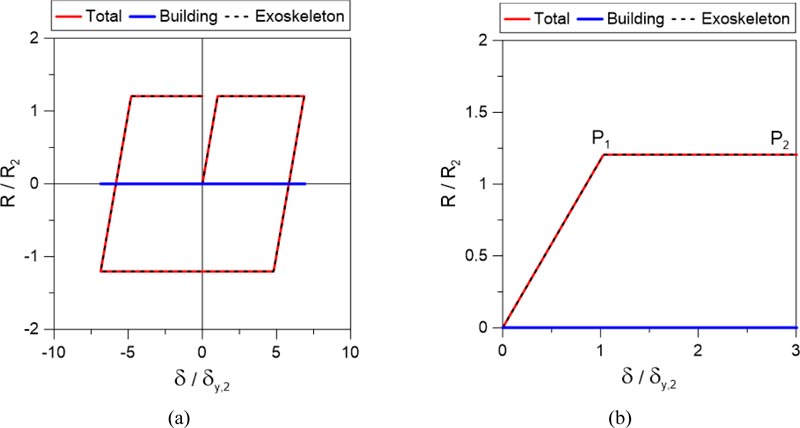
Finally, the in-plane seismic response of the hybrid EXO-3 system inclusive of coupled sliding devices for the RC columns is proposed in Fig. (8). Compared to the previous retrofit solutions, the intrinsic advantage is that the BLD frame behaves as a fully isolated rigid body under seismic loads (Fig. 8b). Accordingly, the stiffness (segment 0-P1) and resistance (P1) parameters of the total hybrid assembly fully reflect the behaviour of the steel exoskeleton alone. In other words, the hybrid solution assumes the structural features (and thus benefits) of the steel exoskeleton.
In this context, it is clear that the steel structure should be optimally designed based on the expected input seismic loads. At the same time, the sliding devices for the RC columns must also be optimized in the design of details. In general, the advantage of such an approach derives from the decoupled response of the base stiffness for the RC structure to retrofit. For this reason, the stiffness of the steel exoskeleton should be high enough to limit the lateral displacements due to the sliding system.
In these conditions, however, the overall design process can efficiently take advantage of the behaviour factor of the steel structure (qTOT= qEXO), as well as of the high ductility and plastic dissipation of the exoskeleton itself (segment P1-P2, in the example).
| - | Columns | Beams | ||||
|---|---|---|---|---|---|---|
| Floor |
Section [cm2] |
Rebars | Plastic hinges |
Section [cm2] |
Rebars at support | Plastic hinges |
| 1st | 65×45 | 4Φ14 + Φ6/15 stirrups |
M3 + P-M2-M3 (h=1%, ϕu=4.86×10⁻³) |
30×45 | 4Φ16 top + 0 bottom |
M3 (h=1%, ϕu =20×10-3) |
| 2nd | 65×45 | 4Φ14 + Φ6/15 stirrups |
P-M2-M3 (h=1%, ϕu =4.86×10⁻³) |
30×45 | 4Φ16top + 0 bottom |
M3 (h=1%, ϕu =20×10-3) |
| 3rd | 50×45 | 4Φ14 + Φ6/20 stirrups |
P-M2-M3 (h=1%, ϕu =4.83×10⁻³) |
30×45 | 4Φ16 top + 0 bottom |
M3 (h=1%, ϕu =20×10-3) |
| 4th | 50×45 | 4Φ14 + Φ6/20 stirrups |
P-M2-M3 (h=1%, ϕu =4.83×10⁻³) |
30×45 | 4Φ16 top + 0 bottom |
M3 (h=1%, ϕu =20×10-3) |
4. ANALYSIS OF A MULTI-STOREY BUILDING
4.1. Reference RC Frame
As a further attempt of validation and assessment of the proposed design concept, a plane multi-storey building is also investigated. In order to define the optimal configuration for the design of the key parameters for a steel exoskeleton applied to an MDOF system of an existing RC building, a multi-storey plane frame is analysed with SAP2000 computer software [23]. The RC frame is a two-bay, four-storey frame, with 5m wide spans and 3m high floors (Rck 300, the resistance class for concrete and FeB44k for the steel reinforcement).
The frame members are loaded with a seismic combination of permanent and accidental vertical loads that were taken into account during the seismic analysis of the structure, and in particular:
- G1: dead loads of all the RC elements (automatically computed by the software);
- G2= 26.12kN/m and Qk= 8kN/m: additional distributed permanent and accidental vertical loads assigned to the RC beams (based on a slab with a 4m influence length).
The design details (beam and column sections and reinforcement details) are summarized in Table 2.
4.2. Retrofit
Similar to the case of the SDOF system earlier investigated, five different FE numerical models are developed, consisting of three main different models and two additional models that are derived from MOD_02, where:
- MOD_00: is the existing non-isolated RC frame;
- MOD_01: represents the non-isolated RC frame connected to a traditional exoskeleton system (with steel members for the bracing system that yield simultaneously at different storey levels);
- MOD_02: the RC frame, with a cut at the base of the columns (for the installation of the sliding devices) and connected to a steel braced exoskeleton (in practice, the sliding devices can be placed more easily in the middle of the base columns). Differing from MOD_01, the bracing members of the 1st floor are only expected to yield and a BRB (Buckling Restrained Brace) is proposed, while all the other steel members of the exoskeleton are expected to remain elastic and stiff under the imposed seismic loads. It is worth mentio- ning for this design solution that the plasticization of upper-floor diagonals does not allow to maximize the structural performance of the coupled system. The hyperstaticity of the hybrid structure and the congruence of floor displacements would, in fact, manifest in internal moments (and thus progressive damage) of the RC beams.
Two additional models (MOD_03 and MOD_04) are finally added to investigate how possible high friction of the sliding devices could affect the retrofit solution:
- MOD_03: is the RC frame with sliding devices at the base, accounted for with a rigid-plastic link, with a yielding force calculated as the friction force for a high friction coefficient of 5%. Such RC frame is connected to the same steel exoskeleton of MOD_02 (just the bracing member of the 1st floor is expected to yield);
- MOD_04: represents the RC frame with sliding devices at the base, accounting for a rigid-plastic link, with a yielding force calculated as the friction force for a friction coefficient of 10%, to simulate a possible seizure of the sliding. Such RC frame is connected to the same steel exoskeleton of MOD_02 (just the bracing member of the 1st floor is expected to yield).
In the analysis, for the MOD_01, MOD_02, MOD_03 and MOD_04 solutions, the exoskeleton is connected to the RC frame by rigid links at the level of each storey. In the case of the MOD_02 solution, the sliding devices at the base of the RC building are introduced without any friction, in MOD_03 and MOD_04, the sliding devices are deeper investigated by considering that they can present different levels of static friction. For this reason, the constitutive law of the link representing the sliding device is characterized by a yielding force equal to the static friction force and hardening of 1%, representing small kinetic friction. The exoskeleton is designed as a rigid pinned structure composed of HE450B columns and HE360B beams (S355, the resistance class). Additional bracing diagonals are separately calibrated for each one of the examined design solutions. In particular, in the case of MOD_01 (rigid base for the RC frame), a concentric X bracing steel system with dissipative zones in tension diagonals only is coupled with the RC frame. All diagonals are assumed to yield almost simultaneously under the effects of a triangular-shaped in-plane lateral load. For this reason, the diagonals are designed to resist the shear forces at each storey, calculated for linear static analysis of the frame. In this case-study example, among other possible solutions, the bracing diagonals are thus assumed with sections HEA180 at the 1st floor, HEA160 at the 2nd, HEA140 at the 3rd and HEA100 at the 4th floor, respec- tively, considering only the tensile braces active.
In the case of MOD_02, MOD_03 and MOD_04, where the RC frame is cut at the base and sliding devices are introduced, the bracing system is composed of stiff X diagonal bracings at the 2nd, 3rd and 4th floor (2×HEA300), that do not buckle and remain elastic. At the level of the 1st storey, a single BRB diagonal (HEA120) is calibrated on the base of the input design seismic load. In this case, the bracing of the 1st storey gives the whole plastic behaviour of the hybrid structure, while the RC frame and the upper part of the steel brace remain elastic. An important intrinsic advantage of this hybrid system is that the ductility of the exoskeleton can be chosen inde- pendently from the characteristics of the existing RC building, which remains in every case undamaged until the collapse of the exoskeleton. In Table 3, the first three modes of each configuration are presented, with their periods of vibration and modal masses. The vibrational modes of MOD_03 and MOD_04 are not reported as they are very similar to MOD_02.
Fig. (9) shows the deformed shape of MOD_01 and MOD_02. In MOD_01, the RC frame is deformed, its inter-storey drifts are due to the deformation of the exoskeleton and for this reason, it can be damaged during an earthquake if the exoskeleton is less stiff. In MOD_02, the RC frame moves almost like a rigid body, as the exoskeleton is rigid in the upper floor and concentrates all the deformation in the 1st (or ground) floor, where the RC frame is decoupled from the soil.
4.3. Push-over Analyses and Results
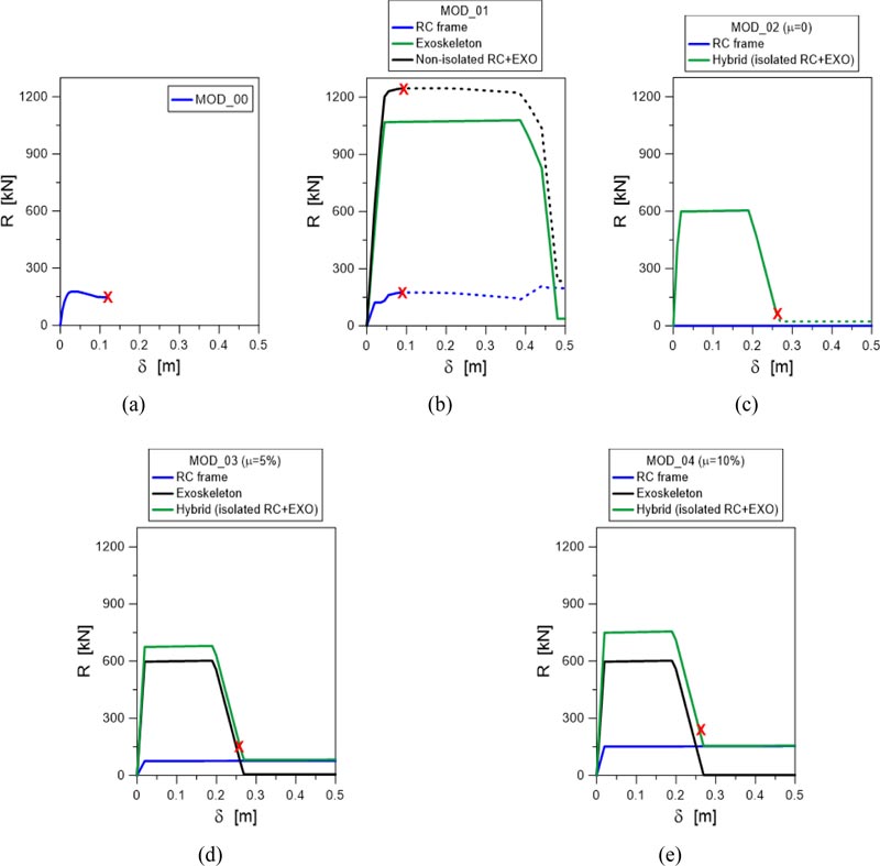
Nonlinear static (push-over) analyses were carried out on the five models earlier described (under triangular load pattern for the in-plane seismic forces), which typically resulted in the force-displacement curves proposed in Fig. (10) and Table 4. The introduced Red Cross points highlight the collapse of the plastic hinges at the base of the 1st storey RC columns. In this regard, it is interesting to see that the base section of the RC columns (1st storey) collapses at the same amplitude of lateral displacement δ for the MOD_00 and MOD_01 solutions, although the resistance of the braced MOD_01 system is much higher. On the contrary, in MOD_02, no significant damage in the hinges of RC beams and columns is observed.
| - | Mode No. |
Period [s] |
Modal Mass | Sum of Modal Masses |
|---|---|---|---|---|
| MOD_00 | 1 | 0.469388 | 0.774 | 0.774 |
| 2 | 0.139137 | 0.135 | 0.908 | |
| 3 | 0.069277 | 0.055 | 0.963 | |
| MOD_01 | 1 | 0.305313 | 0.79234 | 0.79234 |
| 2 | 0.099741 | 0.134 | 0.92635 | |
| 3 | 0.05326 | 0.05167 | 0.97802 | |
| MOD_02 | 1 | 0.346573 | 0.98557 | 0.98557 |
| 2 | 0.09735 | 0.01428 | 0.99985 | |
| 3 | 0.052022 | 0.00003 | 0.99989 |


| - | Building Performance | ||
|---|---|---|---|
| - |
Rmax [kN] |
δmax [m] |
Collapse |
| MOD_00 | 177 | 0.09 | Base of RC columns |
| MOD_01 | 1247 | 0.09 | Base of RC columns |
| MOD_02 | 604 | 0.26 | No (collapse of the base steel diagonal) |
| MOD_03 | 680 | 0.26 | No (collapse of the base steel diagonal) |
| MOD_04 | 756 | 0.26 | No (collapse of the base steel diagonal) |
In order to avoid the collapse of the hinges of the RC building, the solution of MOD_02 is then the most suitable and efficient. The overall resistance of the hybrid solution is significantly enhanced compared to the un-retrofitted RC frame. At the same time also the ductility is increased and it can be estimated and compared to the RC frame alone in Fig. (10a). In the same way, also the MOD_03 and MOD_04 solutions in Fig. (10b) give similar results, although the sliding devices account for their real friction forces.
In all three cases with sliding devices, the RC frame is in fact subjected to almost null deformations and all the resistance and ductility of the retrofitted hybrid system are given by the braces of the 1st floor, that can be easily calibrated at the design stage and even replaced during the lifetime of the structure, in case of damage.
The seismic demand is efficiently transferred from the brittle RC members towards the steel assembly. The overall design benefit can be noticed at different levels. First, the RC building can, in fact, behave in the same way as a fully base-isolated system under a general input seismic event. At the same time, the steel exoskeleton itself can be optimally designed for the given design seismic loads, thus exploiting at best its resistance, ductility and dissipation capacities.
Fig. (11) shows how the base shear is subdivided between the RC frame and the steel exoskeleton, for all the five numerical models, compared to the total seismic response of the system. Red cross symbols give evidence of collapse mechanisms at the base columns for the RC frame (Figs. 11a and b) or in the ground floor steel brace of the exoskeleton (hybrid solution).
4.4. Analysis of Collapse Mechanisms
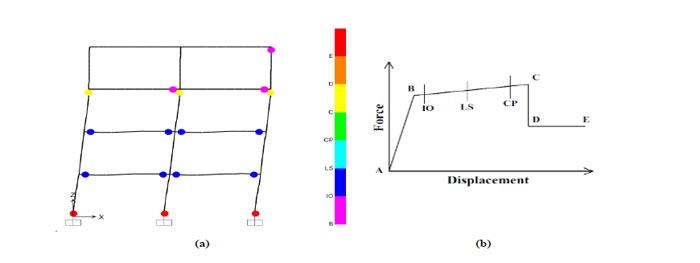
The following figures show the deformed shape that was observed at the last step of the nonlinear push-over analyses performed with SAP2000. The coloured dots indicate the formation of plastic hinges, as described in the legend (the letters correspond to the points of the definition of plastic hinges).
Fig. (12) shows the behaviour at collapse for the RC frame alone. Besides the very low resistance (around 200 kN) and limited displacement capacity of the structure, the overall collapse of the frame is governed by the plastic hinges at the base (level “E” in Fig. (12b), thus beyond the “Collapse Prevention” performance limit). It is of interest that relevant damage can also be noticed for some RC beams (level “C”, that still exceeds the “CP” limit). Figs (13-14) show the behaviour at the collapse of the other four models of the retrofitted structure.
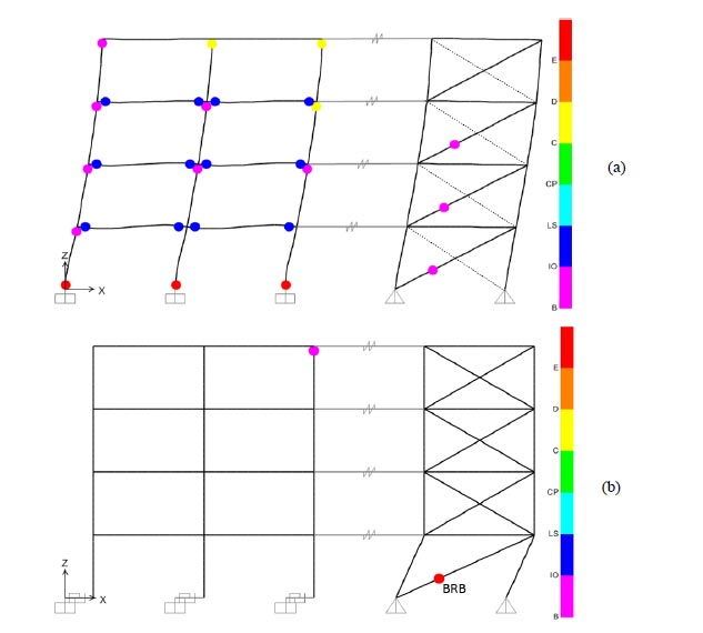

When the steel exoskeleton is first introduced for the non-isolated RC frame, the MOD_01 collapse configuration can be seen in Fig. (13a). Due to the high ductility of the bracing system, the in-plane deformation of the hybrid system causes the collapse of some of the plastic hinges in the beams of the RC frame (“C” level) and at the base section of the RC columns (level “E” for all the plastic hinges).
This is a strong limitation for the design of the steel structure. The total resistance of the hybrid system is high (more than 1200kN, as it can be seen in Fig. (10) and Table 4, that is ≈7 times the RC frame alone for the selected members), and suggests the potential capacity of the retrofitted structure to resist the input design seismic load. On the other hand, when the brace enters the plastic phase, the RC structure is already severely damaged.
On the contrary, in MOD_02, MOD_03 and MOD_04, when the base brace of the exoskeleton collapses, the RC frame has almost no damage, as it can be seen in Figs. (13b and 14).
In case of MOD_02, it is possible to notice that the RC frame remains mostly elastic (just one hinge reaches level “B” corresponding to a slight activation of the plastic hinge, under the “Immediate Occupancy” limit). At the same time, the exoskeleton withstands all the input seismic loads, thus resul- ting in a total resistance that is in the order of ≈3÷4 times the un-retrofitted RC frame and ductility that can be around 2÷3 times higher. Such an effect is mostly governed by the diagonal member at the base of the steel structure, whose axial force-horizontal displacement coincides with the push-over curve earlier presented in Fig. (10). As the RC structure remains elastic, the base diagonal of the exoskeleton can be designed for even stronger seismic events and be easily changed in case the regulations during the lifespan of the structure change the input design horizontal forces. The rigid connections between the existing RC frame and the exoskeleton can be engineered with stiff steel elements.
5. DESIGN PROCEDURE
In order to draft a practical guideline for the design of the proposed hybrid solution (isolated RC frame + exoskeleton), some basic steps to follow are herein summarized (Fig. 15). The overall design method is based on the non-linear static analysis (pushover) method, in order to account for the non-linear behaviour of both the existing RC frame and the newly introduced steel exoskeleton. As a simple alternative, a design procedure that is based on linear analyses with the use of the exoskeleton’ behaviour factor q is still possible, but not advisable, as it is always recommended to run a pushover analysis to check that all the elements behave as desired.
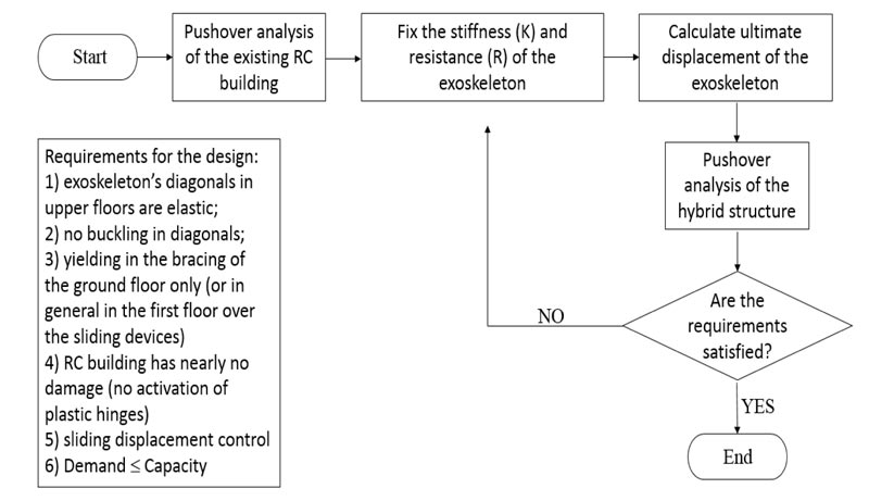
In this context, the fundamental steps can be summarized as follows:
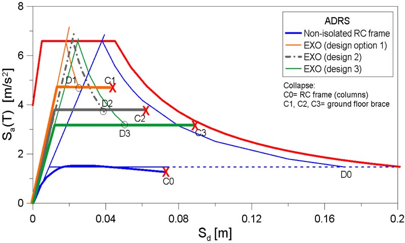
- (1) Analysis of the existing building. The capacity curve needs to be plotted in the ADRS format as in Fig.(16), where the capacity of the building can be checked based on the given response spectrum at Ultimate Limit State (ULS). The Modified Capacity Spectrum Method (MCSM) proposed by Fajfar [24] and reported in Eurocode 8 [25] provisions can be used for this purpose.
- (2) Elastic stiffness and resistance of the exoskeleton. The desired stiffness (and thus the fundamental period) of the exoskeleton and its resistance are fixed. The stiffness and the resistance are regulated by the BRB element on the ground floor. The stiffness of the upper storeys must guarantee very limited inter-storey drifts (max 0.5%) and a totally elastic behaviour of the braces.
- (3) Ultimate displacement of the exoskeleton. The ultimate displacement capacity of the exoskeleton (based on the current code in the designer’s country) must be calculated. To optimize the intervention, this parameter should be approximately in the order of 15-20 times the elastic displacement.
- (4) Analysis. The non-linear static (pushover) analysis is carried out on the hybrid structure (isolated RC frame + exoskeleton). The capacity of the system is positive as far as the structural elements of the upper floors and the exoskeleton remains both elastic, while the RC building is nearly undamaged.
- (5) Final check. If all the requirements are satisfied, the design approach can be considered appropriate. In the contrary, the iterative procedure restarts from step #2.
As it can be seen in Fig. (16), the design of the exoskeleton is a designer’s choice and is quite independent of the existing RC building. The base diagonal can be, for example, chosen to be (option 1) stiffer and more resistant than options 2, 3, which are less stiff, less resistant but more ductile. The major limitations are given by the input design response spectrum. For the three different design options that are presented in Fig. (16), expected capacity and demand parameters can be compared to the existing non-isolated RC frame. C1, C2 and C3 points are representative of the displacement capacities of the exoskeleton with three different base diagonals, while C0 is the displacement capacity of the existing RC frame. Further, D0, D1, D2 and D3 denote the displacement demands given by the design response spectrum. From the figure, it is thus possible to see that the original non-isolated RC frame is not verified for the assigned seismic input. Conversely, all three the proposed hybrid retrofit solutions are positively verified for the seismic demand and prove the efficiency of the proposed approach.
CONCLUSION
In this paper, the seismic analysis and retrofit of existing Reinforced Concrete (RC) structures are investigated. Among all the techniques that have been addressed in the literature for the retrofit of existing RC frames, the attention is focused on the potential and efficiency of steel exoskeletons, which are known to significantly improve the seismic performance of existing buildings on the basis of their stiffness, ductility and resistance. The weakness of traditional exoskeletons, as it has also been noticed in the results of the study presented in this paper (MOD_01), is that they are usually designed to remain elastic under seismic load so that the potential ductility ad resistance of the steel exoskeletons cannot be totally exploited and at the end of a seismic event also, the RC building presents damage to the structural elements.
As a further extension of existing research efforts, careful consideration in this paper is paid to the seismic assessment of a hybrid solution based on the use of traditional steel exoskeletons and base sliding devices for the RC frame to retrofit (i.e., planar steel-PTFE sliding devices).
The role of some key mechanical parameters is first explored for a simple Single Degree of Freedom (SDOF) model, representative of the hybrid system. Successively, based on the preliminary SDOF outcomes, the efficiency of the proposed solution is further assessed for a plane multi-storey RC frame.
In this case, the non-linear analysis of the assembled solution confirms the validity and potential of the proposed approach, compared to traditional steel exoskeletons. In the proposed solution, the ductility and resistance of the steel bracing can be totally exploited for the retrofit of the existing building, so that nearly no damage is expected in the RC building after a seismic event, that also means very low costs for retrofit after a seismic event (reasonably, the cost of brace replacement at the ground level of the exoskeleton).
The main goal of the proposed retrofit system is to transform the existing RC building into a structure that behaves like a rigid body, thus decoupled from the ground motion. Once this behaviour is ensured with the sliding devices at the base, the seismic response of the retrofitted hybrid system is mostly governed by the performance of the exoskeleton only. This is also the reason why in this paper it is chosen to concentrate all the ductility in the diagonal of the 1st floor, while the rest of the exoskeleton should behave rigidly. When also the upper floors diagonals yield, this causes differential displacements between adjacent storeys in the RC building, and thus the consequent damage of RC members. An important feature of the proposed retrofit system is hence the design of the “rigid” part of the exoskeleton. The less ductility the RC frame has, the stiffer should be the “rigid part” of the exoskeleton beyond the 1st floor, requiring quite large sections and consequently high costs for realization. On the other hand, the RC frame is assured to remain undamaged under the imposed seismic load, and thus minimizing the costs of damage repair.
Based on the positive outcomes of the preliminary 2D studies presented in this paper, the research should be extended to 3D structural models in order to find the key details that can influence the efficiency of the proposed solution, as well as to find/suggest optimal parameters for design (as for example the ratio between the stiffness and strength of the exoskeleton and that of the existing RC building). Anyway, given that the used base sliders are bidirectional, the presented technique can be easily applied to complex 3D structures, by taking advantage of a combination of 2D exoskeleton systems along the two principal directions of the hybrid structure.
CONSENT FOR PUBLICATION
Not applicable.
AVAILABILITY OF DATA AND MATERIALS
Data supporting the findings presented in the article are available on request.
FUNDING
None.
CONFLICT OF INTEREST
The authors declare no conflict of interest, financial or otherwise.
ACKNOWLEDGEMENTS
Declared none.

