All published articles of this journal are available on ScienceDirect.

The Analysis of Mechanical Behavior of Special Concentrically Braced Single-Story Frames With Ductile Casting Steel Connectors
Abstract
Background:
The special concentrically braced frame (SCBF) is an aseismic structure, but its bracing system exhibits brittle failure and premature buckling connected with the weld fracture of the gusset plate and the post-buckling of the braces; thus, maximizing the role of energy dissipation is difficult.
Methods:
Here, this paper proposes a system of special concentrically braced single-story frames with ductile casting steel connectors. The large inelastic deformation of the bracing system is mainly concentrated in the ductile casting connectors under the earthquake, and the degree of buckling can be reduced. The finite element model of a single-story frame with special central support and casting steel connectors was established by ABAQUS. Monodirectional loading simulations were conducted on 12 groups of specimens with different parameters, then the deformation trend, stress distribution, initial stiffness, and ductility of the specimens were analyzed.
Results:
The seismic behavior of the frames was evaluated by the variable parameters of the width-thickness ratio of the energy dissipation plate and stiffener, the length of the energy dissipation segment of the casting connectors and the overstrength coefficient. The casting steel connector conducts the main connectors that exhibit good ductile and initial stiffness.
Conclusion:
The study results provided direct evidence that the seismic performance of specimens is closely associated with the length of the energy dissipation segment of the casting connector and the overstrength coefficient of axial force. Also, the stress distribution, initial stiffness, and ductility of the members can be independently controlled by reasonably designing the casting connector.
1. INTRODUCTION
The special concentrically braced frame [ 1] is a kind of structural system with good seismic performance through using global buckling of braces as a viable energy-dissipation mechanism. It has the advantages of high bearing capacity and high lateral stiffness of center supported frame and good ductility of special bending resistant steel frame. And support is the key element to determine the performance of the structure. After Japanese scholars proposed Buckling-Restrained Brace (BRB) in 1973 [ 2, 3], as typical supporting components, it was widely used in existing frame supporting structures. Compared with traditional braces, buckling-restrained braces (BRB) are a kind of brace that relies on its core component that could be confined with a peripheral component from buckling to achieve full-section yield [ 4, 5]. To release expansion and contraction of the core component in the vertical and horizontal directions, the core component and the peripheral component are required to retain a certain gap [ 6]. The gap is generally filled with filler materials to provide better-confined action [ 7, 8]. Watanbe et al. put forward the relationship between the elastic buckling strength of outer constraints and the yield strength of the inner tube based on the test of BRBs [ 9]. Cai ke-shuan et al. in Taiwan developed a double-sleeve and double-kernel model of brace out theoretical analysis and test [ 10]. In 2005, Jian-Bin Liu proposed a simplified seismic calculation method for buckling-restrained brace steel frames, and summarized the theoretical key design points of buckling-restrained brace steel frames and buckling-restrained braces [ 11]. Yun Zhou et al. in 2009 put forward the new buckling-restrained energy dissipation brace design ideas of “partial weakening of a core unit is equivalent to a strengthening of other parts” and two new prevent buckling-restrained energy dissipation brace design schemes of “opening” and “slot type” by summarizing the types pf buckling-restrained energy dissipation brace and analyzing the defects of the existing prevent buckling-restrained energy dissipation brace [ 12]. Since then, Yin et al. added a contact ring between the inner and outer components to improve the double-tube BRB [ 13]. In 2020, Zhan-Zhong Yin et al. designed a kind of buckling-restrained brace that can be assembled with the frame and easily replaced after an earthquake, aiming at the brittle failure of the traditional welding connection and the failure of the support to play its due role in the connection between the support and the frame beam-column [ 14].
However, because the way of connection between the support and frame was welding, the distribution of stress in the node area is complex, and the high triaxial stress field is generated at the connection, which results in the failure of the energy dissipation performance of the support. Therefore, in this paper, the casting steel connector is used to replace the joint plate and buckling restrained brace connection, so as to prevent the brittle failure of the joint area and improve the energy dissipation capacity of the brace. The BRB introduces the casting steel connector at the ends in an attempt to produce a system with reliable strength, stiffness, and deformation capacity. A cruciform cross-section has been chosen for the cast component geometry, which is especially detailed to enhance energy dissipation and increase low cycle fatigue life, thereby reducing the likelihood of fracture [ 15]. The finite element model of a single-story frame with special central support and casting steel connectors was established by ABAQUS. The influence of the length of the energy dissipation section of the buckling restrained brace and the overstrength coefficient of the casting steel connector and the core tube on the bearing capacity, stress distribution, strain distribution, ductility and initial stiffness of the frame was analyzed. It is concluded that the seismic performance of steel frames with casting steel connectors is significantly improved compared with the welding method.
2. MATERIALS AND METHODS
2.1. Establishment of Finite Element Model of Single-Story Buckling-Restrained Brace Steel Frame
2.1.1. Finite Element Establishment of Buckling-restrained Brace with Casting Steel Connector
Here, this paper proposes a system of double-tube buckling-restrained brace with casting steel connectors for steel SCBFs. The design of the casting steel connector is shown in Fig. ( 1).
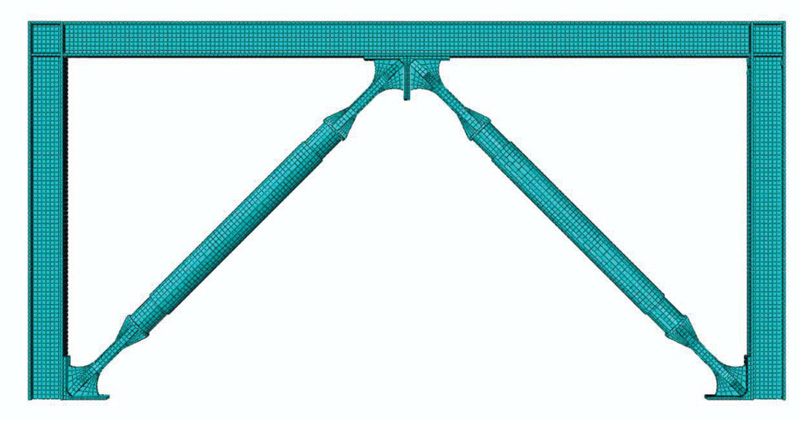
The design of the model was carried out by using three-dimensional finite-element solid modeling software. The geometric parameters of the buckling-restrained brace are shown in Table 1, and the geometric parameters of casting steel connectors are shown in Table 2. The grid division diagram of the overall components of the casting steel connector is shown in Fig. ( 2).
Table 1.
| Specimen Number | The Length of the Specimen /mm | Component Parameters |
Overstrength Coefficient |
||||
|---|---|---|---|---|---|---|---|
| Inner-tube | Outer-tube | Inner-tube | Outer-tube | Contact Ring | |||
| Number | Specifications | ||||||
| KF-1 | 960 | 760 | Φ80×4 | Φ96×5 | 3 | Φ86×3 | 0.80 |
| KF-2 | 960 | 760 | Φ80×4 | Φ96×5 | 3 | Φ86×3 | 0.80 |
| KF-3 | 960 | 760 | Φ80×4 | Φ96×5 | 3 | Φ86×3 | 0.80 |
| KF-4 | 960 | 760 | Φ80×4 | Φ96×5 | 3 | Φ86×3 | 0.80 |
| KF-5 | 960 | 760 | Φ80×4 | Φ96×5 | 3 | Φ86×3 | 0.80 |
| KF-6 | 960 | 760 | Φ80×4 | Φ96×5 | 3 | Φ86×3 | 0.80 |
| KF-7 | 960 | 760 | Φ80×4 | Φ96×5 | 3 | Φ86×3 | 0.80 |
| KF-8 | 960 | 760 | Φ80×4 | Φ96×5 | 3 | Φ86×3 | 0.70 |
| KF-9 | 960 | 760 | Φ80×4 | Φ96×5 | 3 | Φ86×3 | 0.87 |
| KF-10 | 960 | 760 | Φ80×4 | Φ96×5 | 3 | Φ86×3 | 0.91 |
| KF-11 | 960 | 760 | Φ80×4 | Φ100×7 | 3 | Φ86×3 | 0.80 |
| KF-12 | 960 | 760 | Φ80×4 | Φ106×10 | 3 | Φ86×3 | 0.80 |
| Specimen Number | Specification of Casting Steel Connector /mm | Chief | ||||||
|---|---|---|---|---|---|---|---|---|
| L1 | L3 | L2 | t | W | b | d | ||
| A-1 | 150 | 90 | 90 | 16 | 25 | 36 | 37 | 330 |
| A-2 | 150 | 90 | 90 | 18 | 22 | 36 | 40 | 330 |
| A-3 | 150 | 90 | 90 | 20 | 20 | 38 | 38 | 330 |
| A-4 | 150 | 90 | 90 | 22 | 18 | 40 | 36 | 330 |
| A-5 | 150 | 90 | 90 | 24 | 16 | 42 | 34 | 330 |
| A-6 | 150 | 105 | 75 | 18 | 22 | 36 | 40 | 330 |
| A-7 | 150 | 120 | 60 | 18 | 22 | 36 | 40 | 330 |
| A-8 | 150 | 90 | 90 | 16 | 21 | 35 | 36 | 330 |
| A-9 | 150 | 90 | 90 | 21 | 21 | 33 | 46 | 330 |
| A-10 | 150 | 90 | 90 | 18 | 25 | 40 | 40 | 330 |
| A-11 | 150 | 90 | 90 | 18 | 22 | 36 | 40 | 330 |
| A-12 | 150 | 90 | 90 | 18 | 22 | 36 | 40 | 330 |
2.2. Finite Element Establishment of Single-story Buckling-restrained Steel Frame
The height and span of the frame are 1.2m and 2.4m, respectively. The beam section is H150×150×6×6, and the column section is H150×150×6×8. The plane stiffness at the bottom of the frame structure with special central support is infinite. The reduced integral element C3D8R was used in the model, and the plastic deformation analysis of the casting steel connector in the stress process is more accurate by using a smaller mesh size. The material of the inner tube and outer sleeve was Q345B, its constitutive model adopted the Von Mises multi-linear isotropic hardening trilinear model. The material of casting steel connector was Q235B, its constitutive model adopted the ideal elastic-plastic model, Young's modulus E = 2.06 × 10 5Mpa, Poisson ' s ratio = 0.3. The material stress-strain curve of steel is shown in Figs. ( 3 and 4). The material property curve of the casting steel connector is shown in Fig. ( 3). The material property curve of the inner tube, contact ring and outer sleeve is shown in Fig. ( 4). The special central support frame with casting steel connectors was numbered KF1 ~ KF5, and the finite element model of the frame is shown in Fig. ( 5).
3. BASIC THEORY OF BUCKLING-RESTRAINED BRACE PERFORMANCE
3.1. Yield Displacement Angle
Fig. ( 6) shows the schematic diagram of the concentrically braced frame. The initial configuration of the structure is the same as the current configuration when the buckling-restrained brace frame has a small deformation, so it can be assumed that the 0 in the structure is unchanged. And then, the lateral stiffness of the single-layer structure of the buckling-restrained brace was calculated as follows:
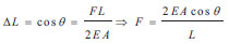
The axial displacement of single support, ∆ L, is:
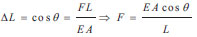 |
(1) |
The horizontal component of support, F n, is:
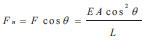 |
(2) |
The lateral stiffness of single diagonal brace, K D, is:
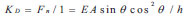 |
(3) |
The herringbone support, as shown in Fig. ( 6), can be equivalent to the joint action of two monoclines, so the axial displacement, ∆ L, is:
 |
(4) |
The lateral stiffness of herringbone braces, K D, is:
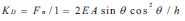 |
(5) |
Assuming that the cross-sectional area of the inner unit is A, when the support enters the yield, the yield strength of the inner unit reaches ƒ y. Then, it can be concluded that the yield force of the support in the horizontal direction is:
The yield stress of the single diagonal brace, F Y, is:
 |
(6) |
The yield stress of chevron buckling restrained braces, F Y, is:
 |
(7) |
So the yield displacement of the buckling-restrained brace, u y, is:
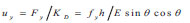 |
(8) |
According to the above Equation ( 8), it can be seen that the yield displacement u y of the buckling-restrained brace is only related to the material properties, support height and tilt angle of the supporting member. It is independent of the section size of the frame and the layout of the support (chevron braces, one-way diagonal support) and the section area of the supporting core.
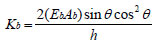
In this paper, Q345 steel is used for the inner tube and outer tube, and both ends of the support need to be articulated with the frame. The yield displacement angle of the buckling-restrained brace, 0 DY, is:
 |
(9) |
In this paper, the angle of support is 30° <0 <60°,so the yield displacement angle range of buckling-restrained brace can be obtained as: 1/298 < 0 DY< 1/259
It can be seen from above that the yield displacement angle of the buckling restrained brace is less than the specification requirements of the elastic story drift ratio limit under a small earthquake. This shows that the condition of support yielding prior to the frame is easy to meet, and the support may have yielded under small earthquakes and entered the plastic stage.
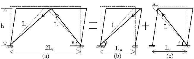
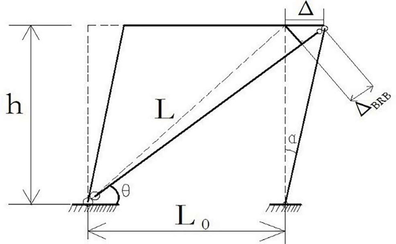
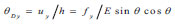
The China’s code stipulates that the limit of elastic story drift ratio of steel structure is 1 / 250, and the limit of elastic-plastic story drift ratio is 1 / 50. Buckling restrained brace as energy dissipation components should remain in the elastic stage. In the elastic-plastic stage, the buckling-restrained brace should enter the plastic state to dissipate energy. From the above derivation, it can be seen that the yield displacement of a buckling restrained brace does not depend on the layout form of support. So, in order to simplify the calculation, the monocline support is taken to indicate that the support has entered the plastic stage under frequent earthquakes. Monoclinic braced steel frame is shown in Fig. ( 7). When a small deformation occurs, the relationship between the relevant parameters can be obtained.
 |
(10) |
The total deformation of buckling-restrained braces can be obtained from a geometric relationship.
 |
(11) |
Under the limit of elastic inter-story drift ratio, the axial displacement of the support is:
 |
(12) |
Under the limit of elastic-plastic inter-story drift ratio, the axial displacement of the support is:
 |
(13) |
3.2. Lateral Stiffness Ratio
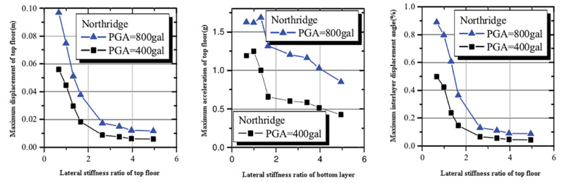
The buckling restrained brace with casting steel connectors is generally divided into monoclinal and herring-shaped. The main connection parts of casting steel connectors exist in the beam-column joint and column-foot joints, and the local design depends on the design of the overall structure. When the cross-sectional area of the core element increases, the lateral stiffness of BRB and the deformation resistance of the structure become stronger, so the lateral displacement of the structure decreases under horizontal load. However, when the area of BRB core unit continues to increase, the lateral stiffness of the structure will be too large, and the absorbed seismic energy is more, but the overall lateral displacement of the structure shows an increasing trend. In order to give full play to the performance of BRB in buckling restrained brace frame, its lateral stiffness ratio is one of the important indexes. Therefore, the lateral stiffness ratio should be determined before the design. Jian-Bin Liu [ 11] of Tsinghua University carried out a finite element simulation of a three-story frame. The simulation showed that the displacement and acceleration of the top floor decreased when the lateral stiffness ratio was greater than 2, but the influence on the structure was not obvious when the lateral stiffness ratio was greater than 3. It is suggested that the lateral stiffness ratio should be between 2 and 5. The relationship is shown in Fig. ( 8).
The elastic-plastic time history analysis of four three-span frames was carried out by Ying Zhao of Tsinghua University [ 16]. The results showed that the story drift ratio decreases with the increase of lateral stiffness and tends to a constant value. Therefore, it is suggested that the lateral stiffness ratio should be between 1 and 3.
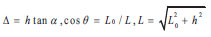
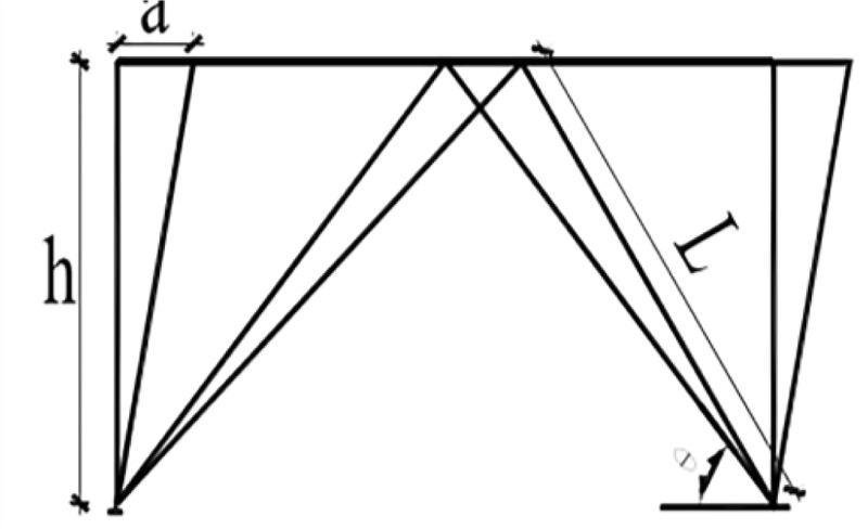
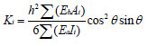
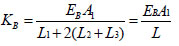
The relationship between BRB and steel frame is deduced theoretically by taking BRBF arranged in the shape of a chevron as an example. As shown in Fig. 9, it is assumed that the structure has a slight lateral displacement along the horizontal direction, and the axial deformation of the beam is ignored, it can be considered that the angle does not change, then the lateral stiffness K B of the chevron-shaped support can be written as:
 |
(14) |
Where, A b is the sectional area of the inner element, E b is the elastic modulus of the core element of support, and h is the height of the frame column.
Assuming that the lateral displacements of the same column are equal, the horizontal lateral stiffness K a of the frame structure can be obtained according to the D-value method [ 17]:
 |
(15) |
Where Σ(EaIi) is the sum of the bending stiffness of the i-story column, E a is the elastic modulus of the material used in the column, I i is the moment of inertia of the column, α is the correction coefficient of the line stiffness of the beam-column, which is related to the line stiffness of the beam-column.
The lateral stiffness ratio is the ratio of BRB horizontal lateral stiffness K b to frame horizontal lateral stiffness K a, then the structural lateral stiffness ratio K i can be expressed as:
 |
(16) |
According to Equation (16), the influencing factors of lateral stiffness ratio are only section size and the angle of support arrangement, which have little relation with the form and quantity of support arrangement. The overall lateral stiffness can be regarded as a linear superposition of the horizontal lateral stiffness of the frame and support [ 18]. In design, it is generally considered that the horizontal lateral stiffness K a of the frame is fixed, and the overall lateral stiffness ratio is adjusted by changing the value of K b.
3.3. Equivalent Stiffness of Buckling-restrained Braces
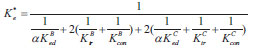
The stiffness of BRB can be regarded as the stiffness of the inner element, which is composed of the connecting segment, the transition segment and the energy dissipation segment. The steel performance and section area of each part are different, so it is necessary to make an equivalent treatment for its stiffness. According to the stiffness series principle [ 19], the equivalent stiffness K b of the supporting member in the elastic stage is:
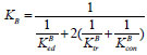 |
(17) |
Where K edB is the stiffness of the BRB energy dissipation segment, K trB is the stiffness of the BRB transition segment, and K conB is the stiffness of the BRB connection segment. K can be obtained by Equation K i = EiAi/Li, where E i is the elastic modulus, A i is the sectional area of the corresponding position, and Li is the length of the corresponding position.
It is assumed that L1, L2,L3,A1,A2 and A3 are the length and sectional area of the core segment, the connecting segment and the transition segment, respectively, and E B is the stiffness of the core element. In order to simplify the calculation, sectional changes of L2 and L3 are usually ignored. And assuming that the sectional area of the core unit is constant A 1, then Equation ( 17) can be simplified as follows:
 |
(18) |
After the support enters the yield stage, both the connection segment and the transition segment should be in the elastic stage. Only the core segment becomes the plastic state, and the stiffness of the core segment needs to be adjusted. According to the assumption of the double broken line model, by introducing the stiffness ratio α, the formula can be expressed as:
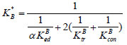 |
(19) |
Where the stiffness ratio coefficient of buckling restrained brace is generally 0.02 ~ 0.05 [ 20].
3.4. Equivalent Stiffness of Castings and Buckling-restrained Brace
The overall stiffness of the buckling-restrained brace with casting steel connector can take the stiffness series principle to obtain. The equivalent stiffness K C of the casting in the elastic stage is:
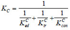 |
(20) |
K Ced is the stiffness of the energy dissipation segment of the casting part, K Ctr is the stiffness of the transition segment of the casting part, K Ccon is the stiffness of the connecting segment of the casting part. Then the line stiffness of the buckling restrained brace with casting steel connector under the elastic stage is:
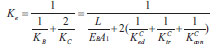 |
(21) |
Then, by using the Equation K e = F e / ∆ e , the load on the elastic limit of the whole specimen in the elastic stage can be obtained.
After the support enters the yield stage, the BRB transition segment is still in the elastic stage, and only the ductile casting part and energy dissipation segment of BRB become the plastic state, and the stiffness of the energy dissipation segment needs to be adjusted. The equivalent stiffness can be changed into:
 |
(22) |
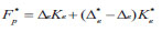
The bearing capacity is determined by formula F p = ∆ LK according to the buckling restrained brace design principle of ductile casting. The energy dissipation segment of ductile casting is the first to yield, and the stress is the largest, so the elastic ultimate F p that the energy dissipation segment can bear should be
 |
(23) |
When the axial displacement of the support reaches 1/50, the ultimate load of the support in the elastic-plastic stage can be calculated by Equation ( 24).
 |
(24) |
4. ANALYSIS OF UNIDIRECTIONAL LOADING RESULTS
4.1. The Bearing Capacity
The following conclusions can be drawn from Fig. ( 10) and Table 3:
(1) According to Fig. ( 10), the development of KF-1 ~ KF-12 under horizontal loading went through three stages: elastic stage, yield stage and plastic strengthening stage. The load and displacement increased linearly in the elastic stage, and the curve rose rapidly, indicating that it has good stiffness. At this time, a buckling restrained brace acts as the first line of defense of the structure. According to the stress nephogram of the loading process, with the continuous loading, the stress of the casting steel connector and the inner tube increased rapidly, and the casting steel connector reached the yield, but the inner tube had not yet yielded. As the load continued, the buckling restrained brace inner tube reached yield stress, and this stage is the yield stage. With the continuous loading, the casting steel connector is completely out of work, and the buckling-restrained brace relies on the plastic deformation of the inner tube to dissipate energy. As this time, as the last line of defense, the pure frame bore all the horizontal loads and the curve began to rise slowly to provide the final safety. This stage is the strengthening stage.
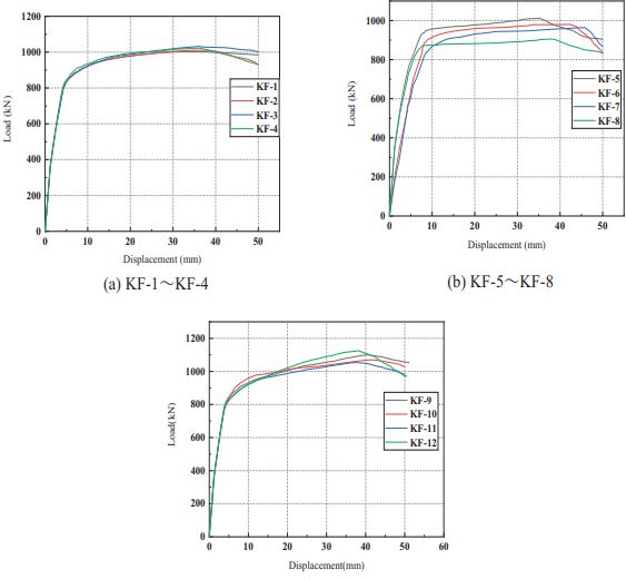
Table 3.
| Specimen Number | Yield Load
/KN |
Yield Displacement /mm | Ultimate Load
/KN |
Limit Displacement
/mm |
Ductility Coefficient | Initial Stiffness /KN·mm -1 |
|---|---|---|---|---|---|---|
| KF-1 | 880.28 | 7.61 | 1002.73 | 34.78 | 4.57 | 115.94 |
| KF-2 | 888.87 | 7.50 | 1010.88 | 35.44 | 4.72 | 118.45 |
| KF-3 | 893.44 | 7.44 | 1037.24 | 36.45 | 4.90 | 120.09 |
| KF-4 | 912.64 | 7.46 | 1022.91 | 36.13 | 4.84 | 122.34 |
| KF-5 | 927.63 | 7.39 | 1011.37 | 35.33 | 4.78 | 125.53 |
| KF-6 | 833.46 | 7.62 | 980.18 | 42.33 | 5.56 | 109.38 |
| KF-7 | 785.77 | 7.87 | 964.27 | 45.76 | 5.81 | 99.84 |
| KF-8 | 871.74 | 7.46 | 905.42 | 38.55 | 5.17 | 116.86 |
| KF-9 | 909.34 | 7.99 | 1100.52 | 40.18 | 5.03 | 113.81 |
| KF-10 | 932.03 | 8.22 | 1072.72 | 41.54 | 5.05 | 113.32 |
| KF-11 | 887.11 | 7.72 | 1054.48 | 37.15 | 4.81 | 114.90 |
| KF-12 | 886.16 | 7.73 | 1124.60 | 38.24 | 4.94 | 114.57 |
(2) According to the comparison of KF-1~ KF-5 in Table 3, it can be seen that the overstrength coefficient of the energy dissipation segment and the inner tube is the same, but the width-thickness ratio of the energy dissipation plate is 2.31, 2.22, 1.90, 1.64 and 1.42, respectively, and the width-thickness ratio of the stiffener is 1.44, 1.64,1.90,2.22 and 2.63 respectively. As the width-thickness ratio of the energy dissipation plate and stiffener changes, yield load and ultimate load are almost the same. Therefore, it can be concluded that the width-thickness ratio of stiffeners and energy dissipation plates will affect the ultimate load and yield load of the frame, but this factor is not the main influence.
(3) By taking the same overstrength coefficient but different energy dissipation lengths, KF-2, KF-6 and KF-7 are obtained. It can be seen that the yield load of KF-7 is longer than that of KF-2, and the ultimate load is reduced by 13.1% and 3.99%, respectively. It can be seen that the length of the energy dissipation segment is the main factor affecting the bearing capacity of the specimen.
(4) The buckling restraint ratio is defined as:
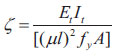 |
E tI t — The bending stiffness of the outer casing;
µ — The calculation length coefficient of two ends constraint;
ƒ y — The yield stress of the inner tube;
A — The sectional area of the inner tube;
When the constraint ratio of the outer tube is inconsistent, the frames KF-2, KF-11 and KF-12 are taken to know that the yield load is almost consistent, and the ultimate load increases by 12.15%. It can be seen that the constraint ratio of the outer constraints has an obvious influence on the bearing capacity of the component.
4.2. Initial Stiffness
The initial stiffness reflects the bearing capacity and stability of the frame. The following analysis can be obtained from Table 3: according to the comparison of frames KF1~KF-5, when the overstrength coefficient was the same, the initial stiffness of the model frame was basically the same. Compared with KF-2 and KF-8~KF-10, the initial stiffness had no obvious change when the overstrength coefficient increased. When the length of the energy dissipation section increased, the initial stiffness decreased significantly. Compared with frame KF-2, the initial stiffness of KF-7 decreased by 18.6%. It can be seen that the length of the energy dissipation segment of the casting steel connector has a significant impact on the initial stiffness of the frame.
4.3. Ductility Analysis
The results in Table 3 show that the ductility coefficients of each frame are 4.57 and 5.81. It can be seen that the special central support steel frame with casting steel connectors has good ductility and deformation ability.
(1) By comparing frame KF-1~KF-5, it can be seen that the ductility of the frame increased by 2.28% when the ratio of the width-thickness ratio of the stiffener and the width-thickness ratio of the energy dissipation plate changed from 0.62 to 1.00; when the ratio changed from 1.00 to 1.85, the ductility of the frame decreased by 4.06%. Therefore, it can be seen that only when the width-thickness ratio of the energy dissipation plate and stiffener of the casting steel connector is controlled in a reasonable range, the structure has good ductility. It is recommended that the width-thickness ratio of the energy dissipation plate and stiffener be set at 0.74~1.73.
(2) Compared with frames KF-2,KF-6 and KF-7, when the overstrength coefficient of casting steel connector and the inner tube was consistent, the ductility of the frame was significantly improved by increasing the length of the energy dissipation segment. When the length of the energy dissipation segment increased from 90mm to 120mm, the ductility of the frame was improved by 27.1%. It can be seen that the length of the energy dissipation segment has an obvious influence on the ductility of the frame.
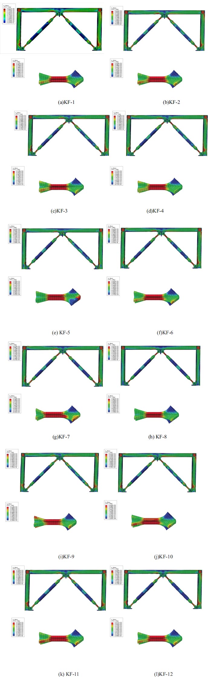
4.4. Stress Analysis under Unidirectional Loading
The stress distribution of each frame is basically similar, as shown in Fig. ( 11), the maximum stress occurred at the column foot and the end of the loaded beam. The stress of the rest of the frame was very small. The energy dissipation segment of the casting steel connector located in the column foot and the middle of the beam reached the yield stress. The stress of the transition segment of the casting steel connector is very small, and did not reach the yield stress. The stress of the outer casing as a constraint unit did not change significantly from the beginning to the end of loading, and the stress was small. The maximum stress of the frame reached 460.3MPa, which was mainly distributed in the area composed of column foot and beam end stiffening plate. As shown in Fig. ( 11), the maximum stress of the casting steel connector was 415 MPa, which was mainly distributed in the energy dissipation segment of the casting steel connectors. It fully shows that the protective effect of ductile casting steel on the structure is obvious.
5. RESULTS AND DISCUSSION
There was no significant difference in the stress distribution of specimens. Only the member stresses of CBRB-8 and CBRB-9 under loading displacements were considered, as shown in Fig. ( 12), to facilitate the illustration of some main characteristics of the stress distribution for two sets of specimens. The stress of each part of the specimen is very small at the compression rate δ=1/810, and the global specimen was in the elastic stage. Then the specimen was in the elastoplastic stage at δ =1/216. Notably, the stress value of L 1 exceeded the yield strength, that is, the energy dissipation segment caused the inelastic deformation to dissipate energy at the moment, while the rest of the components were maintained in the elastic phase. The stress of the connection segment (L 1) of CBRB-8 was far less than the yield stress. Compared with that of CBRB-1, they all reached the yield strength under compressive load. In addition, the stress difference between the energy dissipation segment and the BRB inner tube at δ=1/216 loading displacement was significantly increased compared with that at δ=1/810. The energy dissipation segment entered the full section dissipated energy, as δ reached 1/157, whereas the stress of the connection segment and the transition segment of CBRB-9 were both still in the elastic stage. Fig. ( 12a) clearly shows that the stress of the inner tube of CBRB-8 exceeded the yield load to dissipate energy at δ=1/127, where both L 1 and L 3 remained in the elastic phase and the stress variation began to level off. But, the stress of the inner tube of CBRB-9 exceeded the yield load to dissipate energy at δ=1/157. The casting connector and the BRB were jointly involved in energy dissipation at this time, which seemed to be illogical.
Significantly, the energy dissipation segment (L 2) is the region of maximum stress for the whole specimen in any loading phase, which suggests the feasibility of protecting the other components by weakening the cross-section of L 2 to concentrate most of the stresses in the energy dissipation segment. The stress distribution result showed that the
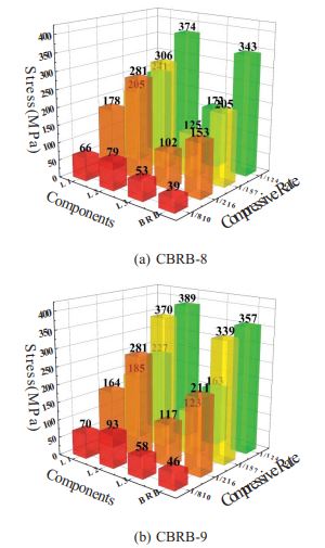
improved casting connectors (the L 1 and L 2) were consistently maintained in elasticity, which ensured stable force transmission in the CBRB system and avoided brittle fracture due to residual stress in traditional welded gusset plates. The energy dissipation segment of the casting connector first turned into plasticity and was followed by the inner core of BRB in a plastic state. This condition achieves the goal of the system to dissipate earthquake energy in stages.
A casting steel connector was used for a special concentrically braced steel frame to change the stress distribution mode of the frame. The casting steel connector reached the yield stress before the frame in the loading process due to the low yield stress of the energy dissipation segment. The energy dissipation segment entered the yield of the full section with the loading process. Subsequently, the stress of the inner tube gradually increased, and the stress of the frame did not reach the yield stress except for the column foot node and the beam end of the loading point. It can be seen that the stress distribution mode of the frame is significantly improved by using casting steel connectors as energy dissipation components.
Remarkably, the BRB was involved in energy dissipation as the compression rate reached 1/124, but this result is not significant for KF-9 and KF-10.
Then the stress of the inner tube gradually increased, and the stress of the frame did not reach the yield stress except for the column foot joint and the beam end of the loading point. It can be seen that taking the casting steel connector as an energy dissipation element can obviously improve the stress distribution mode of the frame. This special phenomenon occurred because the rigidity of the casting connector reached a level that caused the assembled BRB to become a weak member, thus resulting in local instability at the late loading stage, which is unfavorable to the continuous energy dissipation for the specimen. Therefore, the axial force overstrength coefficient should be set within a reasonable range to ensure the energy dissipation performance of casting connectors.
CONCLUSION
In this study, 12 models of concentrically braced frames with ductile casting steel connectors were selected for the finite element analysis of monodirectional loading. The bearing capacity, stiffness and ductility of the frames were analyzed with parameters including the width-thickness ratio of the energy dissipation plate and the stiffener, the overstrength coefficient of the casting steel connector and the inner tube, and the constraint ratio of the outer tube. The major finding of this study is summarized as follows:
1) The failure mode of the special concentrically braced frame with casting steel connector belongs to ductile failure. Thereby confirming that the casting steel connector can help prevent brittle failure and premature buckling connected.
2) In the initial loading process, the energy dissipation segment of the casting steel connector entered the yield stress. As the loading process continues, the inner tube also enters the yield stress state. Except for the loading point and column foot position, the stress in all parts of the beam and column is very small and does not reach the yield stress. The stress distribution results that L 1 and L 2 of the casting connector are consistently maintained in elasticity, which ensures stable force transmission while avoiding brittle fracture due to residual stress in traditional welded gusset plates.
3) The axial force overstrength factor represents a space for plastic development in the energy dissipation segment, which is closed related to the cross-sectional area of the energy dissipation segment. In this study, the axial force overstrength coefficient should be less than 0.87, which is an excessively large factor unfavorable for energy dissipation of the specimen in stages.
Several analytical studies have been conducted on the special concentrically braced single-story frames with casting steel connectors, and the findings of this research provide insights for future work into ductile connectors of bracing systems. The conclusions are based on an analytical study, and future studies should include experimental validation of the results of this theoretical study.
CONSENT FOR PUBLICATION
Not applicable.
AVAILABILITY OF DATA AND MATERIALS
The data that support the findings of this study are available within the article.
CONFLICT OF INTEREST
The authors declare that they have no known competing financial interests or personal relationships that could have appeared to influence the work reported in this paper.
FUNDING
The research presented in this paper is part of Project (2019YFD1101003) supported by the National Key R&D Program of China, research Project (JK2021-22) of Gansu provincial department of housing and urban—rural construction and Project (51968044) supported by the National Natural Science Foundation of China.
ACKNOWLEDGEMENTS
We thank Zhanzhong Yin, Lanzhou University of Technology, for the comments that greatly improved the manuscript. In addition, the authors would like to acknowledge the support from the Lanzhou University of Technology in China for experimental equipment for this research.

