All published articles of this journal are available on ScienceDirect.

Shear Strengthening of Reinforced Concrete Beams Using GFRP
Authors Info & Affiliations
Abstract
Background:
Glass fibre-reinforced polymer (GFRP) is often used as external strengthening material due to its unique benefits. However, the effectiveness of the strengthening configuration, which uses GFRP in different orientations, still has a lot of uncertainties.
Objective:
This research work aims to study the shear strengthening of reinforced concrete beams using GFRP.
Methods:
The mechanical properties of the GFRP were investigated, including tensile and flexural tests. Two layers of GFRP were bonded together using epoxy and a hardener of 2:1. The GFRP was then cut according to size for tensile and flexural tests. Five samples were prepared for tensile and flexural tests, respectively. In terms of beam strengthening, a total of four beams were considered for four-point bending tests, whereby two were used as control beams and the remaining two were for strengthening purposes. A 45º strengthening configuration was adopted for the shear strengthening.
Results:
Results showed that GFRP possessed the highest tensile stress, which was achieved in the range of 208.85 MPa – 319.22 MPa, while the highest flexural stress was achieved in the range of 506.16 MPa – 592.49 MPa. The results showed that shear strengthening at 45º with GFRP achieved an ultimate load of 136.38 kN, which was higher than the control beam's load of 133 kN. This indicates that GFRP managed to regain the beam capacity, which is 2.5% higher than the control beam.
Conclusion:
This proves that GFRP can be used as an alternative strengthening material other than carbon fibre-reinforced polymer (CFRP).
1. INTRODUCTION
Concrete is one of the important materials in modern buildings, which provides strength and durability to the structures. However, during the service life of a building, the concrete encounters various conditions such as inadequate structural design, poor construction management as well as maintenance, improper usage of the building, corrosive environment, settlement of the foundation, abnormal natural disasters, atmospheric effects, and so on, which will affect the strength [1]. Besides that, the disturbance of the reinforced concrete (RC) structure during its service life can be due to the creation of openings in existing structures. The opening is to accommodate pipes and duct services that may affect the strength of RC members [2]. As a result, these factors will either reduce the beam’s structural capacity or exceed the beam’s serviceability limit, which will later lead to the failure of the RC beams. The failure in RC beams usually occurs either in flexural or shear failure. Unfortunately, failure in shear has a greater impact compared to failure in bending in reinforced concrete (RC) beams. The occurrence of shear failure usually comes without any warning and is more common than flexural failure [3]. Thus, more concern should be given to the beam’s structural capacity in shear.
Strengthening of RC members was conducted to restore and extend the RC structures’ service life through conventional methods. For example, installing a metallic plate at the external layer of the structure, wire mesh, post-tension system, concrete, steel jacketing, and injection of epoxy have been applied to enhance the beam’s capacity [4]. Recently, the utilisation of fibre-reinforced polymer (FRP) as an external strengthening material has become popular due to its superior properties, such as higher longitudinal tensile strength, lightweight, resistance against chemical attack, strength-to-weight ratio, and ease of installation [4, 5]. FRP is a material that contains two or more constitutions while, generally, the fibre and matrix are the main constitutions and either the fibre or the matrix has different mechanical properties [6]. Fibre could be classified into two categories, which are natural fibre and synthetic fibre, while there are two types of matrix, which could be thermostat resin and thermoplastic resin. By combining these materials with different properties, the FRP could be easily designed for a special purpose and provide outstanding performance.
Fibre-reinforced polymer (FRP) has been utilised as an external shear strengthening in the RC beam, either in the form of side wrapping, U-wrap, or full wrapping of the beam section to improve the RC beam’s shear capacity. Carbon fibre was one of the popular materials in FRP [7, 8]. Although carbon FRP had greater mechanical properties than the glass fibre reinforced polymer (GFRP) and other types of FRP, however, the GFRP provided better corrosion resistance, especially in an alkaline environment, better energy absorption properties, and most importantly, it was more economical than the carbon FRP [5, 9, 10].
Due to the consideration of the economic aspect, GFRP is used in the shear strengthening of RC beams [11-14]. The GFRP with different widths was installed at 90° on the RC beams’ side surfaces [12]. Montaser et al. [12] concluded that the maximum width of GFRP was recommended for improving the shear capacity of the beam and the effect of increasing the number of GFRP layers impacted the longitudinal strain more than the Carbon Fibre Reinforced Polymer (GFRP). Various shear strengthening configurations were presented in [13], where the GFRP was installed in the form of side wrapping with strips or sheets, U-jacketing, and the assistance of an anchor system at an orientation of 90° to improve the T-beam’s shear capacity. Although the shear strengthening by using side wrapping with strips did not improve the shear capacity significantly, the stiffness value of the beam at the maximum load level was higher than the control beam.
Strengthening configuration in shear was also discussed in [11] where the GFRP strips were installed at the angle of 45° and 90°. Two different spacing between strips on the sides of RC beams were considered. As a result, the 45° strengthening configuration with short spacing between strips gives the highest improvement in the shear capacity of the RC beam. Previous work reported that installing the GFRP with more layers of glass fibre, wider width, and shorter spacing between strips with 45° orientation could improve the shear capacity of the beam even though in the form of side wrapping. However, most of the GFRP strips were fabricated on the RC beam during the preparation of the shear strengthening [12-14] instead of prefabricating the GFRP before installation [11]. The prefabricated GFRP strips were found to be easier to install than fabricating the GFRP strips during installation. On the contrary, there is limited research on the shear strengthening of full-scale RC beams using prefabricated GFRP strips at an orientation of 45°. Hence, this work focuses on the study of external shear strengthening of RC beam by installing the prefabricated GFRP at an orientation of 45° in the form of single-side wrapping at the shear zone. The mechanical properties of the GFRP composites were analyzed through tensile and flexural tests. The effectiveness of the strengthening configuration at the shear zone was examined through four-point bending tests.
2. MATERIALS AND METHODS
2.1. Beam Reinforcement Preparation
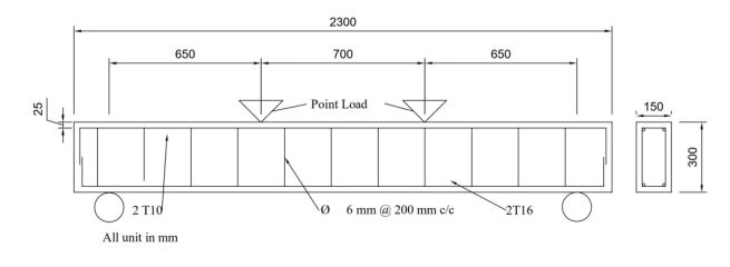
A total of four beams with a dimension of 150 mm × 300 mm and a total length of 2300 mm were prepared. Two longitudinal high-yield steel bars of 10 mm diameter were used as the top reinforcement, while two longitudinal steel bars of 16 mm diameter were used as the bottom reinforcement. The shear link used in the beam was mild steel of 6 mm diameter with spacing 200 mm center to center. The nominal cover of all specimens was 25 mm. Ready-mixed concrete used in this study was with a targeted strength of 35 MPa. Before casting the specimens, the fresh properties of concrete were tested by conducting a slump test according to BS EN 12350-2: 2019 standard [15]. Compressive strength was performed on concrete cubes cast at the size of 100 mm × 100 mm × 100 mm according to BS EN 12390-3: 2019 [16]. Table 1 presents the material properties of the ready-mixed concrete. Table 2 presents the fresh and hardened properties of concrete at 28 days. Fig. (1) shows a schematic diagram of the RC beam used in this study.
| Material Properties | Description |
|---|---|
| Cement type | Ordinary Portland Cement |
| Type of course aggregate | Grade granite |
| Type of Fine aggregate | Natural sand |
| Maximum course aggregate size | 20 mm |
| Grading of fine aggregate | BS 882 grade C or M limit |
| Concrete Properties | Description |
|---|---|
| Target strength | 35 N/mm2 at 28 days |
| Experimental cylinder compressive strength | 34.67 N/mm2 |
| Target slump | 75 ± 25 mm |
| Actual slump | 65 mm |
2.2. Fabrication of Glass Fibre Reinforced Polymer (GFRP)
The method used for fabricating the GFRP strips was the hand lay-up method [17]. Epoxy resin and glass fibre were laid layer by layer with this technique. First, the epoxy resin was applied on both sides of the GFRP sheet evenly, then a second glass fibre sheet was laid on top of the GFRP and lastly, the last layer of epoxy was applied on the second layer of the glass fibre sheet. A total thickness of 2 mm was made standard for all the GFRP composites with epoxy as the binder used in this study.
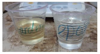
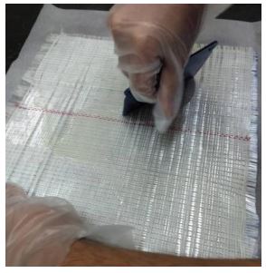
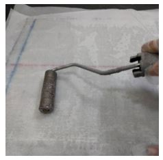
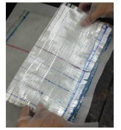
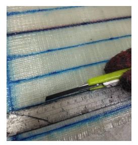
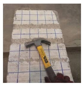
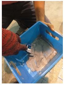
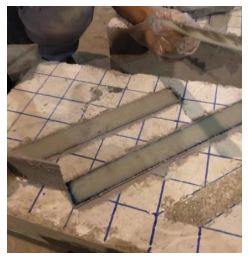
First, two glass fibre-reinforced polymer sheets were cut from the roll according to the size that had been designed earlier. At least 1 cm at each edge of the sheet was left when plotting the location of the strip to maximize the effectiveness of the glass fibre-reinforced polymer strips. Next, two-piece baking papers were prepared where the dimension should be bigger than the sheet and both papers were sprayed with sticker remover to ensure they were easily removed when cured. Later, the volume of the epoxy resin which is required for the thickness of 2 mm was measured, and the resin and hardener in a ratio of 2:1 were prepared in units of grams which were presented in Fig. (2). After that, the hardener was poured into the resin and the mixture was mixed slowly while, at the same time, the time, temperature and humidity were recorded. Then, the glass fibre sheet was placed on the ready-sprayed baking paper on a flat platform. Next, epoxy resin was poured on the glass fibre sheet, and it was applied evenly on the surface by using a scraper which is presented in Fig. (3). The glass fibre was covered with another baking paper and it was rolled to remove excess air bubbles, as shown in Fig. (4). Later, the glass fibre sheet was flipped and a layer of epoxy resin was applied. Again, the glass fibre sheet was covered with another glass fibre sheet as well as baking paper and rolled, as shown in Fig. (5). Eventually, the last layer of epoxy resin was applied to the glass fibre, and later, it was covered with baking paper and rolled to remove excess air bubbles and epoxy resin. Next, the glass fibre sheets were left to cure for two hours, and the half-cured glass fibre sheet was cut with a blade according to the grid line which was plotted earlier, as shown in Fig. (6). The glass fibre strips were fully cured under room temperature, which was around 28 ± 2°C and the relative humidity was in the range of 70% to 90% for 24 hours after mixing the epoxy resin.
2.3. Strengthening Configuration
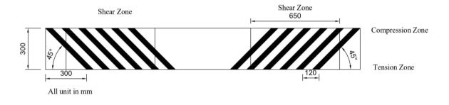
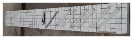
Shear strengthening is considered in this study. The GFRP strips were bonded with Sikadur-30 epoxy adhesive at the shear zone. The size of the GFRP used for strengthening the RC beam was 2 mm thick, 35 mm wide, and 300 mm long. In terms of strengthening configuration, the GFRP composites were placed at 45º concerning the longitudinal section of the beam. It is expected that a 45º GFRP composite could intercept the natural flow path from the point load towards the support to hinder the crack formation [18]. The distance between each composite was approximately 125 mm. Only single-sided side strengthening was considered in this study. Fig. (7) shows the strengthening configuration of the RC beam by using GFRP, while Fig. (8a-d) shows the step-by-step images for the installation of GFRP on the RC beam.
2.3.1. Bonding Agent
Sikadur-30, an epoxy-based adhesive, was used as a bonding agent between the GFRP strips and the concrete beams. The most significant advantage of this agent was that it had high strength in adhesion and was hardened without shrinkage [19]. In terms of shear strength and ultimate load, the epoxy-based adhesive had the best mechanical performance for glass-fiber-reinforced polymer joints [20]. Besides that, it was less influenced by the humidity during curing and no primer was needed during mixing. It consists of two components; Part A in the form of a white colour solution and Part B in a black colour solution. The ratio of both components was 3:1 in terms of volume. After mixing, the mixture obtained was light grey in colour. This bonding agent’s working temperature was around 8 °C until 35 °C. The thickness of this bonding was approximately 3 mm in its optimum state. The application method was according to the manufacturer (Sika Group). Table 3 presents the properties of Sikadur-30. The shear modulus of this material is approximately 1.7 GPa.
| Material Properties | Value (N/mm) |
|---|---|
| Compressive strength | 90 when days of 7 in 35°C |
| Modulus of elasticity in compression | 9600 at the temperature of 35 °C |
| Modulus of elasticity in tension | 11200 at the temperature of 23 °C |
| Tensile strength | 29 when days of 7 in 23°C |
| Shear strength | 18 when days of 7 in 23°C |
2.4. Test Setup
2.4.1. Experimental Tests of GFRP Specimens
2.4.1.1. Tensile Test
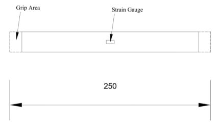
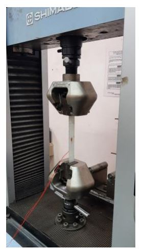
Samples of the GFRP strips were tested in tension using a Universal Testing Machine (UTM) with a capacity load of 50 kN at a rate of 3 mm/min. The test conducted, as well as specimen preparation, was according to ASTM D3039 [21]. The dimensions of the GFRP strips were 25 mm wide and 2 mm thick, with a length of 250 mm. A strain gauge was placed in the middle of the gauge length to record the reading upon testing [22-25]. The ultimate tensile strength was recorded up to the failure of the specimens. Fig. (9) presents the schematic diagram of the GFRP strips in tension. Fig. (10) presents the setup of the tensile test.
2.4.1.2. Flexural Test
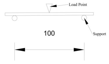
A flexural test was conducted on the GFRP strips using a Universal Testing Machine (UTM) of 50 kN capacity. The testing conducted was according to ASTM D790 at a rate of 2 mm/min [26]. The dimension of the specimens used for the tensile test was 13 mm × 4 mm (width × depth) with a length of 127 mm [22, 27]. From the test, the ultimate load and stress-strain curve were recorded up to the failure of the specimens. Fig. (11) presents the schematic diagram of the GFRP strips in flexural and the test set-up of the flexural test is presented in Fig. (12).

2.4.2. Four-point Bending Test on RC Beams
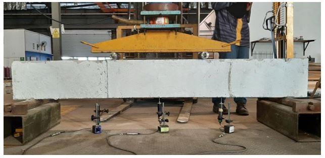
The experimental setup of the beam and procedures were referred to the standard, BS EN 12390-5:2000 [16]. The beam specimens were tested using a universal testing machine with a capacity of 500 kN. All the beam specimens were tested under four-point bending up to beam failure [28]. The load was applied equally to both loading points, which are 700 mm apart, at a rate of 5 kN per minute through a spreader beam. A load cell is mounted at the bottom of the spreader beam to obtain the magnitude of the loading. A total of three linear variable-differential transducers (LVDTs) were placed at the bottom soffit of the specimens to measure the beam displacement. All LVDTs were connected to a data logger to record the concrete strain, load, and displacement of the specimens, respectively, during testing. Fig. (13) shows the set-up of the four-point bending test on the control beam. Crack formation and propagation of cracks were drawn on the beam while the failure mode of the beam and GFRP Strips was recorded.
3. RESULTS AND DISCUSSION
3.1. Tensile and Flexural Stress of GFRP
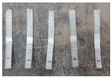
Five samples of GFRP sheets were tested for their tensile properties. Fig. (14) presents the stress-strain result of the GFRP sheets, which consist of 2-ply of glass fibre in each GFRP strip. The results of five samples were found consistent, with a range value between 208.85 MPa and 319.22 MPa, and the average tensile stress of the 2-ply GFRP is 280.6 MPa. The modulus of elasticity of the GFRP strips was identified as 5.2 GPa. Fig. (15) presents the failure mode of the GFRP strips, where those strips were broken into two pieces and the glass fibre was exposed. The trend of tensile stress versus strain was also found to be similar to the past investigation on tensile properties of GFRP plates [29-31]. With the application of load, a linear line was seen as proportional to stress and strain until reaching the ultimate tensile stress. A sharp decrease in stress was observed before the GFRP failure. This may be due to the brittle characteristics of the GFRP [32].
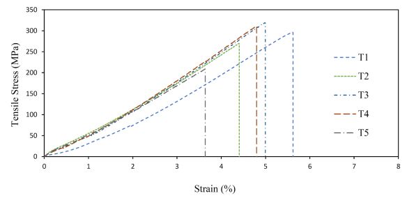
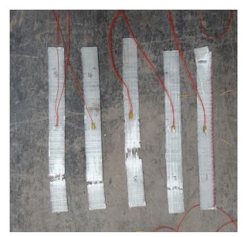
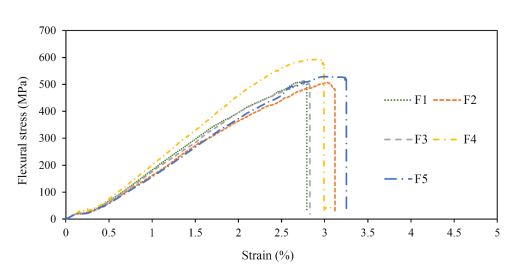
Fig. (16) shows the graph of the stress-strain curve of five GFRP strips tested under flexural conditions. Fig. (17) presents the failure mode of those GFRP strips where the middle part of the strips was delaminated. The test resulted in a flexural modulus of 18.3 GPa and ultimate flexural strength of 592.49 MPa. The range of flexural strength was between 506.16 MPa and 592.49 MPa. A similar trend of the flexural stress-strain curve was observed in the previous study [23]. The flexural stress-strain curve increases linearly with a decrease in slope, indicating stiffness degradation. Stiffness degradation occurred due to internal cracks in the 2-ply samples at about 60% of the ultimate load. The specimens experienced matrix cracking and interlaminar damage at the midspan, which resulted in a reduction of their load-carrying capacity. Flattening of the stress-strain curve at about 2.5% strain where the curve becomes nonlinear occurred due to the development of intra-ply and inter-ply damage [33].
3.2. Shear Strengthening of RC Beams
3.2.1. Load-deflection Behavior
On the other hand, the beam which was strengthened by 45º orientation had a maximum load of 136 kN with a deflection of 10.23 mm, as shown in Fig. (18). The trend in the elastic phase of the strengthened beam was observed to be similar to that of the control beam. A linear line was observed where the load increases proportionally to the deflection. The trend changes when the first crack occurs at a load of 100 kN with a deflection of 7 mm. Subsequently, the load kept increasing in the plastic phase due to the strain hardening with a lesser stiffness up to a maximum load of 136 kN. Upon beam failure, the load-deflection of the strengthened beam with GFRP exhibits more deformation with a progressive decline of load to 100 kN at 15 mm as opposed to a fast decrease in the control beam. The load-deflection curve of the strengthened beam is presented in Table 4. Compared to the control beam, strengthening in the shear zone using GFRP composite at 45º orientation managed to slightly increase the beam capacity up to 2%, greater than the control beam. The load-deflection curve of the strengthened beam was found in line with the findings of Mahendra et al. [34] and Siddiqui [35], whereby the trend of the load-deflection curve showed shear failure.
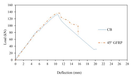
Fig. (18) shows the comparison of load versus deflection of a control beam and a beam strengthened using GFRP strips at 45º orientation. The control beam achieved an ultimate load of 133 kN with a maximum deflection of 10.52 mm. A linear line was observed in the elastic phase where the load was proportional to deflection until the first crack occurred, which was 82 kN at 5 mm of deflection. Due to strain hardening, the load increases in the plastic phase with a slight reduction in stiffness up to the maximum load of 133 kN. A sharp decrease in load was recorded, which indicates that the beam failure was in shear. Table 5 summarizes the trend load-deflection curve of the control beam.
| Status | Load | Description |
|---|---|---|
| Early stage of loading | From 0 to 100 kN | The curve increased linearly. |
| First crack | 100 kN | The first crack on the beam was observed |
| Yield load | 100 kN to 125 kN | The slope of the load-deflection curve dropped slightly. |
| Strain hardening | 125 to 135 kN | The curve became flattened. |
| Ultimate point | 136 kN | The maximum point of the load-deflection curve. |
| Fracture | 136 kN to 100 kN | The curve showed a progressive decline. |
| Status | Load | Description |
|---|---|---|
| Early stage of loading | From 0 to 82 kN | The curve increased linearly. |
| First crack | 82 kN | The first crack on the beam was observed and the load-deflection curve dropped slightly. |
| Strain hardening | 82 kN to 133 kN | The curve increased but with a lesser slope. |
| Ultimate load | 133 kN | The maximum point of the load-deflection curve. |
| Fracture | 133 kN to end | The slope decreased sharply until failure occurred. |
3.2.2. Crack Pattern and Failure Mode
Fig. (19) presents the crack pattern of the control beam while Fig. (20) presents the enlargement section on the crack. Flexural cracks were observed in the midspan of the control beam during the early stage of loading. The vertical cracks penetrated up to the beam neutral axis towards the point load. With the continuous application of load, the vertical cracks eventually shifted to the shear zone. Diagonal cracks were seen forming from the support towards the point load. The crack width of the diagonal crack increases upon beam failure. The maximum width of the crack was approximately 10 mm. The formation of diagonal cracks at the shear zone indicates that the beam failed in shear. The beam shows brittle behaviour with a sudden and abrupt failure.
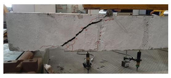
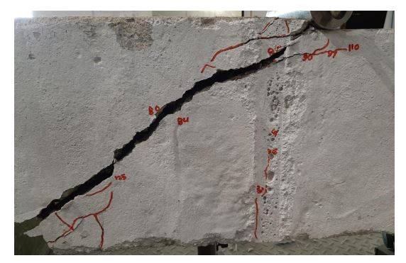
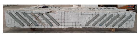
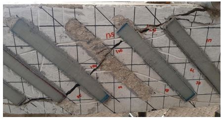
Fig. (21) shows the crack pattern of the RC beam strengthened with GFRP after a four-point loading test. Similar to the control beam, diagonal cracks were seen forming from the support towards the point load. Compared to the control beam, the diagonal cracks were disturbed by the configuration of the 45° GFRP strips, unlike the diagonal cracks in the control beam. The diagonal crack penetrated the bottom edge of the GFRP strips, away from the strengthened area. Eventually, this diagonal crack penetrated up to the beam neutral axis, causing one of the GRFP strips to be debonded from the concrete surface in Fig. (22). No other ruptures of GFRP strips were traced. The diagonal crack then penetrated to the top edge, away from the GFRP strip, towards the point load. This indicates that the presence of GFRP managed to disturb the natural flow path of the crack. The shear failure of the externally bonded GFRP strips to the RC beam was found to be debonding, whereby the CFRP debonded before reaching the rupture of the GFRP strips [36]. Before beam failure, the crack width of the diagonal crack increases, followed by a sudden and abrupt failure, indicating brittle behaviour. The maximum width of the crack was approximately 5 mm, which was smaller than the control beam.
CONCLUSION
This study aimed to investigate the behaviour of the RC beam strengthened with a double-layer GFRP strip at 45° orientation in the shear zone. From the results obtained, the following conclusions can be drawn:
- It was found that the highest tensile strength of the GFRP strips was 319.22 MPa and the maximum flexural strength was 592.49 MPa.
- The arrangement of GFRP strips with a 45º orientation was able to enhance the beam’s original structural capacity by about 2% compared to the control beam.
- Unlike the control beam, the 45º strengthening configuration was able to extend deflection with a steady decrease in load.
- The shear failure of the RC beam was due to debonding of GFRP strips before reaching the rupture of the GFRP sheets. No other rupture of GFRP strips was traced before the beam failure.
- In terms of crack pattern, the strengthened beam had fewer vertical cracks and narrower crack widths, which may be strong evidence that the GFRP strengthening helped.
LIST OF ABBREVIATIONS
| GFRP | = Glass Fibre Reinforced Polymer |
| CFRP | = Carbon Fibre Reinforced Polymer |
| RC | = Reinforced Concrete |
| NSM | = Near Surface-Mounted |
| LVDT | = Linear Variable-Differential Transducers |
| UTM | = Universal Testing Machine |
CONSENT FOR PUBLICATION
Not applicable.
AVAILABILITY OF DATA AND MATERIALS
The data used to support the findings of this study are available from the corresponding author [S.C.C] upon request.
FUNDING
This work was financially supported by UMP Internal Grant PGRS200375.
CONFLICT OF INTEREST
Dr. Ramadhansyah Putra Jaya is the Executive Guest Editor of journal The Open Civil Engineering Journal.
ACKNOWLEDGEMENTS
The authors acknowledged the financial support from UMP Internal Grant PGRS200375.

