All published articles of this journal are available on ScienceDirect.

Low Velocity Impact Response of Reinforced Concrete Flat Slabs
Abstract
Background:
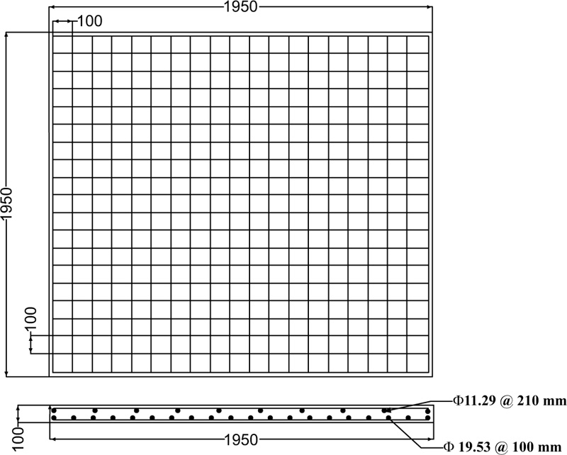
Dimensions of the reference concrete slab are 1950x1950x100 mm subjected to drop-weight impact loading.
Objective:
a comprehensive parametric study was performed to examine the influence of many parameters on the RC slabs.
Methods:
From the viewpoint of cost and time savings, a three-dimensional finite element is a very good tool to predict the real behavior of the structural elements.
Result and Discussion:
Results showed that the use of CFRP strips enhances the impact behavior of the slab. Contrarily, the existence of an opening led to a dramatic decrease in the dynamic capacity of RC slabs with stress concentration around the openings. Furthermore, changing the shape of the impactor showed a significant effect on the peak impact load as well as the ultimate deflection at impact instant.
Conclusion:
In the scope of this paper, the response of RC slab with top and bottom reinforcements exposed to drop-weight impact loading was inspected. Time histories of impact loads and deflections were presented in detail based on ABAQUS/ Explicit analysis. The findings presented in this paper can be presented as follows:
1. The FE models show a good correlation with the experimental data. Consequently, the proposed finite element models are efficient and economical tools to explore the effect of many parameters on the performance of RC slabs subjected to drop-weight impact load.
2. The numerical simulation confirmed that using externally bonded CFRP strips has more influence on the peak deflection of the reinforced concrete slab than the recorded impact force.
3. Comparing to the flat shape of the impactor, the hemispherical and curved shape impactor can produce large penetration depth at the impact zone with higher plastic deformations in the concrete slab. However, the flat impactor produced higher deflection at the impact instant.
4. As the radius of the impactor increases, both the duration time and the peak impact force are increased. This is because the higher contact area was obtained when the flat impactor (infinity radius of curvature) was used as compared to other impactors.
5. Due to decreases in RC slab stiffness, the presence of openings (regardless of their shape) has considerably increased deformations in concrete, especially around the perimeter of the openings extended to the nearby support.
6. It has been found that eccentric impact loading causes higher plastic deformations than concentric ones.
1. INTRODUCTION
A concrete flat slab is a two-way reinforced slab without shear reinforcement [1]. Flat slab is perhaps the most widely used in various structural systems such as buildings and garages [2, 3]. A structure may face many types of dynamic loads like earthquakes, rocks falls, and blasts through its service life, therefore, experts need to extend their knowledge and safety against these threats [4]. Reinforced concrete slabs subjected to drop-weight impact loading are currently under the high interest of researchers [5]. Batarlar and Saatcı [6] tested three pairs of RC slabs with dimensions of 2150x2150x150 mm under static and impact loadings to reveal the differences between these tests. The results showed that the reaction forces developed under impact loading are higher compared to forces under static loading. Xiao et al. [7] presented experimental and numerical studies on lightly reinforced concrete slabs subjected to impact loading. It was found by the researchers that increasing the concrete compressive strength, slab depth, and the diameter of the impacted area increases the energy capacity of RC slabs. Said and Mouwainea [8] investigated the effect of strengthening RC slabs with FRP composites under high-mass low-velocity impact load. The results of this study showed that the defection of the slabs is significantly reduced as the area of the CFRP layer under the impact zone increases. Yılmaz et al. [9] experimentally and numerically investigated the effect of reinforcement ratio on the behavior of simply supported RC slabs subjected to low-velocity impact load. Their results showed that there was an increase in flexural strength and stiffness with the increase in the rebar ratio. In addition, an increase the rebar ratio led to a notable reduction in maximum deflection. The same conclusion was noted by Wang et al. [10] by examining reinforcement ratio between 0.22% ~ 0.40%. Moreover, they found that the increase in the thickness of the slab results in decreasing the damage to the slab surface and the maximum deflection. Also, Erdem [11] conducted experimental and numerical investigations to examine the effect of different reinforcement spacings and dimensions of the slabs on their dynamic behavior. The author found that the impact load increases with the increase in section size and the decrease in reinforcement spacing.
Many researchers found that numerical analysis can solve problems by saving both time and cost [12-15]. Mitrevski et al. [16] studied the influence of various shapes of the impactor on the behavior of thin woven carbon/epoxy laminates including hemispherical, conical, and ogival impactors. The results showed that the hemispherical impactor generated the highest peak impact force as compared to other impactor shapes. A finite element model of reinforced concrete slabs with several support constraints was established by Kishi et al. [17]. The results of impact and deflection time histories were found in good agreement with the experimental results. Shaheen et al. [18] numerically examined the effect of shape (square or circular), and position of opening on the impact behavior. Additional reinforcement bars were added along the edges of the openings. In general, the results revealed that the circular opening shows lower peak deflection in all models compared to square ones. Also, the opening positioned at the mid-side of the slab gives higher deflection and deformation, regardless of their shape.
Different strength-enhancing techniques including steel/CFRP sheets and strips for two-way concrete slab were presented by Anas et al. [19]. It was found that the impact response of the slab improved through using strengthening techniques in terms of deflection and damage severity. Several effective protective measures were numerically proposed by Yang and Zhang [20] using rubber, CFRP layer, steel plate, and polyurea to reduce the deflection and peak stress of RC slabs. Hamza and Madlum [21] found that using externally bonded CFRP sheets to strengthen the tension side of RC slabs delays the appearance of cracks and improves the impact load. Anas et al. [22] found that the most critical location of contact blast on the slab is along the symmetric line of the slab at an eccentricity of one-quarter of its width.
Many researchers suggested that the addition of steel fiber was efficient in enhancing the performance of concrete elements under impact [23-25]. The experimental tests conducted by Hrynyk and Vecchio [26] showed that the addition of steel fiber to the concrete mix was effective in reducing crack widths and increasing slab capacity. Also, Al-Rousan [27] found that the addition of Polypropylene Fiber to the concrete mix delays the growth of the number of flexure cracks, therefore, both stiffness and toughness are improved.
The above-mentioned literature develops a sufficient interest to examine the effect of many parameters on the dynamic behavior of concrete slabs owing to the inadequate number of existing studies. Therefore, this paper extends the previous investigations by the authors on the dynamic performance and damage of flat concrete slabs under drop-weight impact load. A numerical model of reinforced concrete slab is built and validated against the experimental test. Then, full-scaled numerical models are generated and simulated to understand in detail the performance of RC slabs, and to explore the influential factors including strengthening with FRP composite, various shapes of impactors, and the presence of an opening in the slab on the impact resistance capacity of the RC slab. Moreover, this study includes the response mode and damage of reinforced concrete slab directly subjected to drop weight impact load onto the center of the slab and diagonally eccentric impact. As established in the end, this study not only proposes an analytical model of slabs but also provides FE procedures that can be used in the damage assessment of the reinforced slabs under low-velocity impact loading.
2. MATERIALS AND METHODS
According to the experimental study conducted by Othman et al. [28], the dimensions of the reinforced concrete slab are 1950 mmx1950 mm with a depth of 100 mm. The RC slab was constructed with a doubly reinforced arrangement. The bottom reinforcements are 19.53 mm in diameter with a spacing of 100 mm, while the top reinforcement bars are 11.29 mm in diameter with a spacing of 210 mm, as indicated in Fig. (1). The yield and ultimate strengths of the top and bottom reinforcing bars are 451.2 and 629.1 MPa, respectively. High-strength concrete with average compressive strength of 83.1 MPa was considered in the study. The slab was simply supported at its corners. The low-velocity load has been applied to the midpoint of the slab by dropping a 475 kg weight from a constant height, resulting in an 8.95 m/sec impact velocity. The striking weight was manufactured with a 400 mm square hollow section.
3. FINITE ELEMENT MODELING
Numerical modeling has been carried out using Abaqus/Explicit software to model the response of RC slabs subjected to low-velocity impact loading. The explicit module is capable of performing dynamic scenarios such as impact loading. The next section illustrates the details of the formation of the finite element models to obtain a sufficient approximate behavior to the experimental tests that have been carried out by Othman et al. [28].
3.1. Selection of Element Type and Mesh Sensitivity
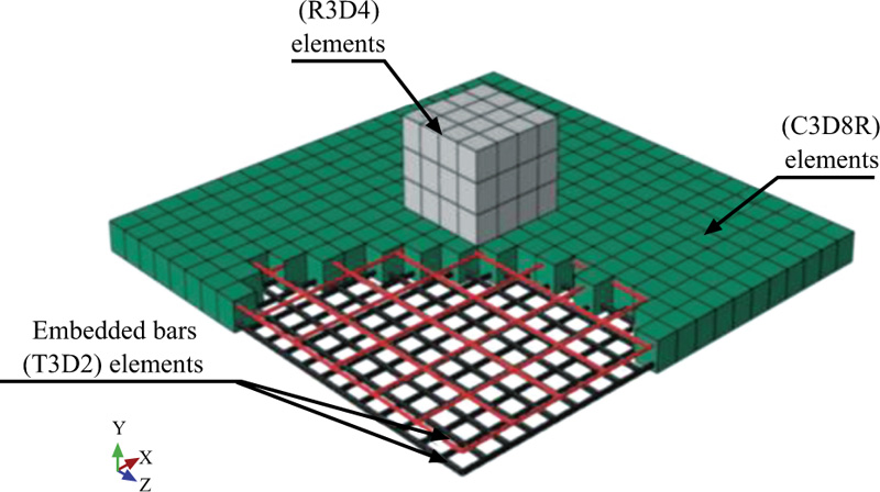
The ABAQUS software offers a complete element library that can model any geometry through combining many elements. Three material parts can be distinguished in this model: concrete, steel reinforcements, and the impactor. In order to develop the concrete slab, the eight-node continuum elements (C3D8R) were used. While for the top and bottom reinforcing bars, two-node three-dimensional linear truss elements (T3D2) were applied. The impact hammer has been simulated as a rigid part using a four-node bilinear quadrilateral element (R3D4). The impactor is simulated in an original location close to the slab surface (60 mm offset) with a predefined velocity assigned to its reference point (RP), which was situated at the center of the hammer. Different mesh sizes were modeled to decide the suitable finite element size for simulation. It is found that a mesh size of 100 mm for the concrete slab and the reinforcement bars gives reliable results in contrast to the experimental results.
3.2. Constitutive Material Model
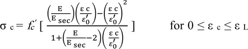
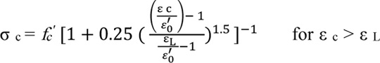
The concrete damage plasticity model (CDP) was used to model the inelastic behavior of concrete by assuming two failure mechanisms, namely tensile cracking and compression crushing. The uniaxial compressive stress-strain relationship for high-strength concrete which is proposed by Lu et al. [29] was selected. This expression is appropriate for a concrete compressive strength range between 50 MPa up to 140 MPa, as follows: (1, 2).
 |
(1) |
 |
(2) |
Where,
σc Concrete compressive stress, MPa.
Esec The secant modulus at ultimate strength (E sec = fc'/ εo'), MPa.
E Modulus of elasticity of the concrete, MPa.
fc' Concrete cylinder strength at 28 days, MPa.
εo' Peak strain at concrete strength fc'.
εc Concrete compressive strain.
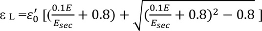
ε L The strain value at a stress level equivalent to 0.8 fc' and can be calculated by
 |
To determine the concrete behavior in tension, the tension stress-strain relationship developed by Hsu [30] was used, as follows: (3, 4).
 |
(3) |
 |
(4) |
Where,
σ t The tensile stress for any point on the curve, MPa.
ε t The tensile strain for any point on the curve, MPa.
εcr The cracking tensile strain at the ultimate concrete tensile stress fcr, MPa.
fcr Cracking tensile stress, MPa.
In addition, five parameters should be defined to model the failure criteria for concrete material in tension and compression, as presented in Table 1. On the other hand, a linear stress-strain relationship was defined to simulate the behavior of the top and bottom reinforcement bars.
| Parameters | Value |
|---|---|
| The dilation angle, ψ | 45° |
| Eccentricity, ε | 0.1 |
| Ratio of biaxial to uniaxial compressive strength, ƒb0 / ƒc0 | 1.16 |
| Second stress invariant ratio, k | 0.67 |
| The viscosity parameter, μ | 0 |
3.3. Interactions and Boundary Conditions
In this work, the embedded algorithm is assumed to simulate the interaction between the reinforcement rebars and the concrete. The technique allows a kinetic boundary conditions constraint between the nodes of reinforcement bars and the nodes of the concrete slab. While general surface-to-surface contact interaction was employed to express the contact between the impactor and the top surface of the concrete slab. Also, this technique has been used to simulate the contact surface of the FRP strips with the concrete surface.
The concrete slab is restrained in x, y, and z directions at its corners to imitate the experimental conditions. The reference point of the impactor was a constraint to move only in the translation direction in y-axis. The arrangement of RC slabs, reinforcing bars, and impactors in the simulation are shown in Fig. (2).
4. RESULTS AND DISCUSSION
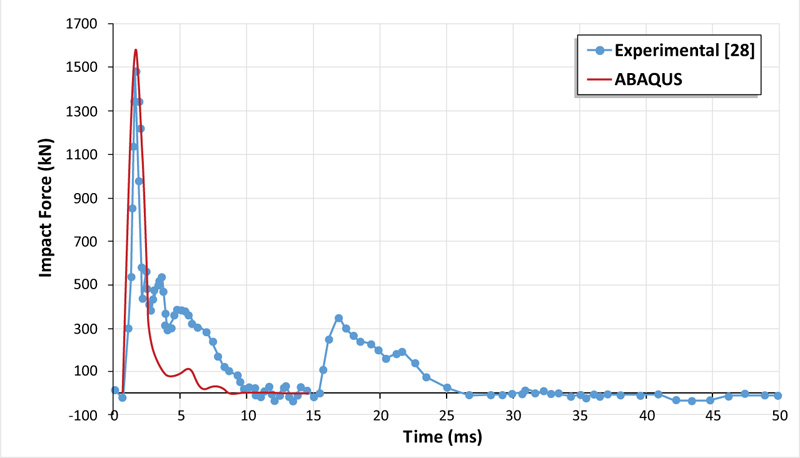
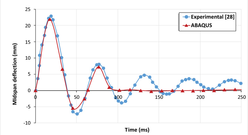
To verify the efficiency of the model illustrated formerly, the finite element analysis results were compared to the experimental ones. The simulated impact load and deflection-time histories are presented in Figs. (3 and 4) respectively. It can be noted that ABAQUS accuracy regarding the peak impact load value was 6% which was 1574.26 kN when compared with the experimental result which was 1479.8 kN. While the simulation results underestimated the ultimate deflection by approximately 5%. For the impact load scenario, it can be observed that there is a good agreement demonstrated between FE modeling and experimental investigation with a similar peak impact load and duration. After that, there is a discrepancy observed between the two plots, after about 3 ms. This difference can be explained as, in the experiment, the impactor strikes and then lost its contact with the slab for many cycles until dampen. This damping effect is not considered in the numerical model, where the impact load reaches its peak and then directly drops to zero.
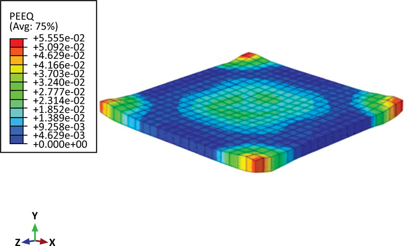
Also, Fig. (5) shows the inelastic deformation of the reinforced slab by using the equivalent plastic strain (PEEQ) in ABAQUS [31]. If this variable is more than zero, it means that the material has yielded. This figure indicates that the dark blue area away from the impact zone is still elastic.
5. PARAMETRIC STUDY
After verifying the effectiveness of the finite element simulation, a parametric study was conducted to investigate the effect of many parameters on the dynamic response of RC slabs under low-velocity impact loading. The following sections discuss the influence of several parameters concerning strengthening the concrete slab with CFRP strips, the shape of the impactor, the presence of a circular hole, and eccentric impact loading.
5.1. Influence of Reinforcing CFRP Strips on the Response of Concrete Slab
The influence of using FRP strips externally bonded into the surface of the concrete slab was examined in this section. The dimensions of the slabs and the reinforcements are kept constant. CFRP composite materials consist of high strength continuous fibers embedded in a polymer matrix [32]. FRP fabric has higher tensile strength, durability, and stiffness, and can be wrapped around any structural elements to improve their strength and ductility [33-35]. The carbon FRP reinforcing strip used in this study has a thickness of 1 mm and a width of 100 mm, and is wrapped around the underside of the concrete slab. The CFRP material is modelled in ABAQUS using the four-node shell element (S4R); while the interaction between CFRP and concrete surfaces was modeled as surface-to-surface contact. A lamina model was defined in ABAQUS/ Explicit to model CFRP strips. This model involves defining many moduli to complete CFRP simulation, as illustrated in Table 2. In addition, to identify the mode of failure of the FRP composite material, Hashin's criterion was used [36].
| Description | Value (MPa) |
|---|---|
| Density | 1.82E-09 |
| Elastic modulus in longitudinal direction, E1 | 21000 |
| Elastic modulus in transverse direction, E2 | 6500 |
| In-plane shear modulus, G12 | 2400 |
| Transverse shear modulus, G13 | 2400 |
| Transverse shear modulus, G23 | 2300 |
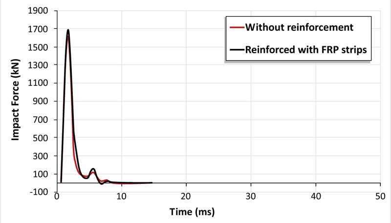
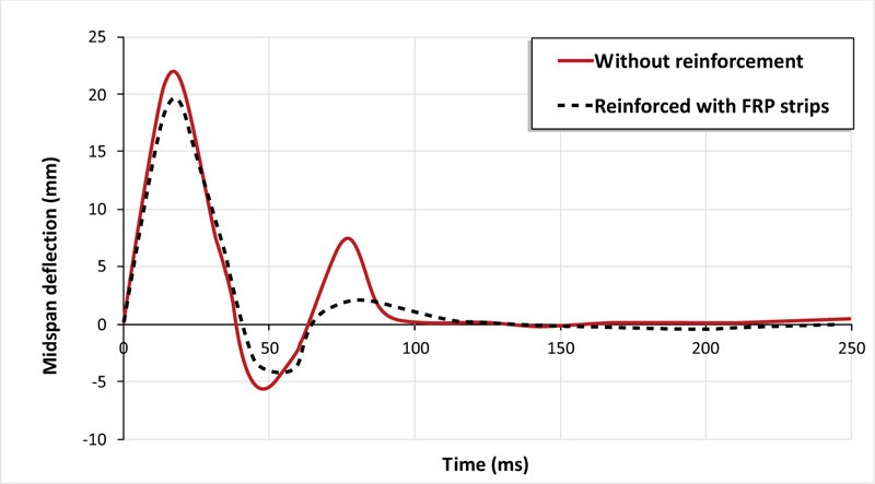
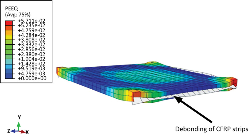
According to the simulation results, as depicted in Figs. (6 and 7), using CFRP strips for reinforce slabs results in a 6% increase in peak impact load with a 12% decrease in deflection compared with the reference slab at the impact instant. This improvement in the dynamic capacity of the RC slab is accompanied by debonding of CFRP material from the concrete slab as detected in Fig. (8).
5.2. The Influence of the Shape of the Impactor on the Response of Concrete Slab
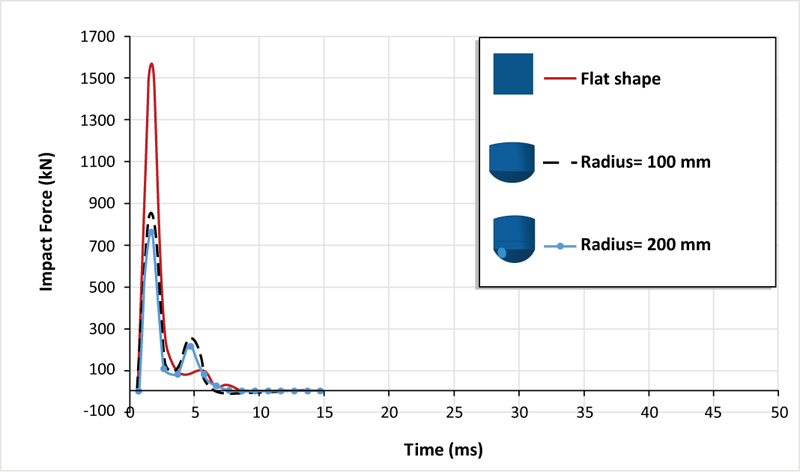
In this section, two shapes of impactor shape are considered, namely, curved surface with a curvature radius of 100 mm and hemispherical shape with a radius of 200 mm. The mass and velocity of the drop weight are kept the same as the drop weight used in the experimental work. The impact load-time histories of the two shape geometries in Fig. (9) show that the peak impact load increases with the increase in curvature radius of the impactor shape. The concrete slab impacted by the hemispherical shape records a lower impact force of 760.36 kN, which is 107% less than that of the infinity radius of curvature (flat shape). While the impact load generated by the curved shape with a curvature radius of 100 mm is reduced by 85% as compared to the flat shape. It is also interesting to mention that there is a difference in impact duration of about 1 ms between the slab impacted by the hemispherical and flat shapes. This can be explained by the impacts of the slab on the flat shape with a large contact area compared to hemispherical and curved shapes, in which only the tips of the curved shapes impact the contact area.
The time histories of peak deflections are shown in Fig. (10). It can be seen that the ultimate deflection decreased from 26% to 51% when changing the impactor shape from hemispherical to curved shape with a radius of 100 mm. Therefore, these plots indicate that the shape of the drop weight significantly affects the ultimate deflection.
From the plastic deformation (PEEQ) illustrated in Fig. (11), the difference in penetration depth between the two shapes of the impactors can be observed. Due to stress concentration, the hemispherical shape causes a larger penetration depth within a small impact area as compared to the curved and flat shapes. The damage behavior obtained is comparable with the data of other authors, such as Kühn and Curbach [37]. The sharp impactor tip produces crushing failure at the top surface of the concrete slab while increasing the radius of the tip leads to a punching-like failure.
5.3. The Response of Concrete Slab with Openings
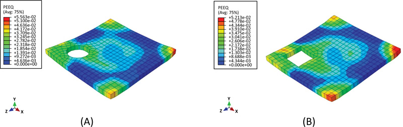
In order to examine the effect of opening a presence in an RC slab on the performance of an RC slab under impact load, two finite element models with openings were created. One of the models contains a circular opening with a diameter of 500 mm located at the corner of the reinforced concrete slab, while the other one contains a square opening with a side length of 500 mm. Both models have the same position of the opening. Referring to Fig. (12), it can be noted that the presence of a corner circular opening reduces the peak impact force by 73%, while the square opening by 50%. Moreover, the comparison of deflection-time histories of RC slabs with and without openings in Fig. (13) indicates that the deflection increased by 43% and 39% for the circular and square openings, respectively. Fig. (14) describes the distribution of equivalent plastic strain, it is clearly shown that the plastic deformation concentrates around the openings and extends to adjacent corners as a consequence of stiffness reduction caused by the openings. Although the deformation along the perimeter of the circular opening is less than that of the square opening, the peak deflection at the midpoint of the slab with a circular opening is higher, about 6%. This result obtained differs from the results stated in the literature for slabs with corner openings. However, the peak impact load of the slab with a circular opening is about 13% higher than its counterpart with a square opening.
5.4. The Response of Concrete Slab Exposed to Eccentric Impact Loading
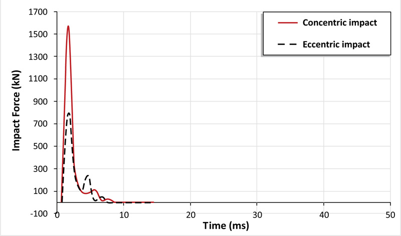
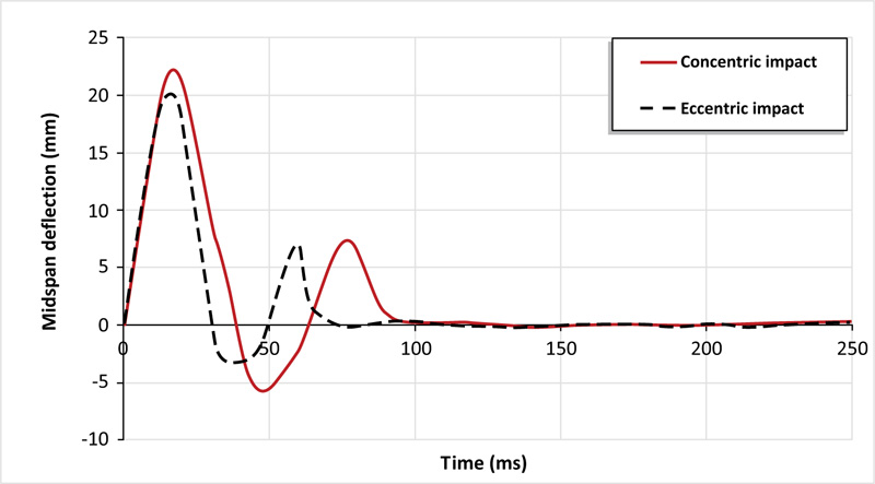
The previous sections clarified the influence of drop weight impact load acting on the centroid of the slab. In this section, the effect of diagonally eccentric impact (487.5 mm away from the impact point) is inspected. The numerical prediction made by ABAQUS model shows that the peak impact load is 801.73 kN (96% lesser than that of the concentric impact of the reference slab), as shown in Fig. (15). From Fig. (16), for eccentric impact, the slab experience less peak deflection 20.3 mm as compared to concentric impact at the impact instant.
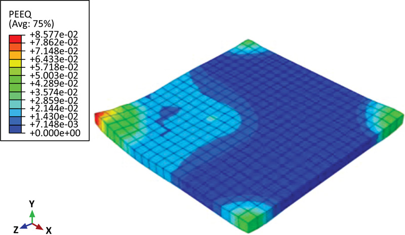
To evaluate the extent of elastic and plastic deformations under eccentric impact load, the (PEEQ) pattern is shown in Fig. (17). It can be noted from this Figure that the diagonally eccentric impact causes more localized damage in the form of plastic deformation as compared to concentric impact.
CONCLUSION
In the scope of this paper, the response of the RC slab with top and bottom reinforcements exposed to drop-weight impact loading was inspected. Time histories of impact loads and deflections were presented in detail based on ABAQUS/ Explicit analysis. The findings presented in this paper can be presented as follows:
1. The FE models show a good correlation with the experimental data. Consequently, the proposed finite element models are efficient and economical tools to explore the effect of many parameters on the performance of RC slabs subjected to drop-weight impact load.
2. The numerical simulation confirmed that using externally bonded CFRP strips has more influence on the peak deflection of the reinforced concrete slab than the recorded impact force.
3. Compared to the flat shape of the impactor, the hemispherical and curved shape impactor can produce large penetration depth at the impact zone with higher plastic deformations in the concrete slab. However, the flat impactor produced higher deflection at the impact instant.
4. As the radius of the impactor increases, both the duration time and the peak impact force are increased. This is because the higher contact area was obtained when the flat impactor (infinity radius of curvature) was used as compared to other impactors.
5. Due to decreases in RC slab stiffness, the presence of openings (regardless of their shape) has considerably increased deformations in concrete especially around the perimeter of the openings extended to the nearby support.
6. It has been found that eccentric impact loading causes higher plastic deformations than concentric one.
LIST OF ABBREVIATIONS
| RP | = Reference Point |
| CDP | = Concrete Damage Plasticity |
CONSENT FOR PUBLICATION
Not applicable.
AVAILABILITY OF DATA AND MATERIALS
The data and supportive information is available within the article.
FUNDING
None.
CONFLICT OF INTEREST
The authors declare that there is no conflict of interests regarding the publication of this paper.
ACKNOWLEDGEMENTS
The authors express their gratitude to the Civil Engineering Department, University of Technology - Iraq and the staff for providing the software support and some references related to this work.

