All published articles of this journal are available on ScienceDirect.

Numerical Study on Discrete Confinement of Circular RC Column Subjected to Eccentric Load
Abstract
Background:
The performance of concrete-filled steel-tube (CFST) columns under axial compression is excellent. However, the steel-tube wall's instability due to insufficient outward restraint from the concrete made the steel tube lose its lateral support, thereby making it more susceptible to buckling.
Objective:
This study aims to propose and investigate a confinement mechanism that can remove the possibility of buckling of the steel tube by introducing gaps and pre-tension to prevent tube detachment from concrete. The investigation was carried out using both experimental tests and numerical simulation.
Methods:
The proposed confinement mechanism consists of thin steel sheets with gaps between them and is pre-tensioned in a staggered scheme. The performance of the proposed confinement mechanism is evaluated through experimental tests and numerical simulations using an in-house 3D-NLFEA package. The observed behaviors are the axial stress-strain, strength index, initial confining pressure, and ductility.
Results:
Experimental works found that the primary failure mode in the compression zone of the strengthened column was due to lateral expansion of concrete which may be attributed to strain localization, longitudinal tensile cracking, and severe concrete crushing. On the other hand, at the tensile region, pure tensile forces occurred, followed by crack opening displacement at the outer tensile fiber region. With the proposed confinement mechanism, the extreme failure event can be reduced. The axial capacity and ductility of the strengthened column were enhanced. The numerical model presented the initial confining pressure by the pre-tensioned steel sheet (a clamping mechanism), which successfully increased the axial load capacity of the slender reinforced concrete (RC) column and reduced the possibility of cover spalling.
Conclusion:
The proposed confinement mechanism to strengthen an RC column was found to successfully enhance the load-carrying capacity and ductility of a slender circular reinforced concrete column.
1. INTRODUCTION
The interaction between steel and concrete materials dramatically enhances the performance of concrete-filled steel tubes (CFSTs), resulting in several benefits. The steel tube serves a crucial role by acting as external confinement, complementing the longitudinal and transverse reinforcement that provides passive confinement. This combined action exerts confining pressure on the concrete, subjecting it to a triaxial stress state. Moreover, the confinement provided by the steel tube prevents the concrete cover from spalling and slows down the crushing of the compressed concrete. However, it is essential to note that concrete and steel materials have different dilation rates. As a result, if the steel tube detaches from the concrete, the tube will behave as an independent element and become vulnerable to outward buckling.
Research on CFST columns under eccentric load has been conducted for several decades, with recent studies explicitly examining the impact of eccentricity and slenderness on the load-carrying capacity of these columns. The flexural buckling of the steel tube in the compressed region has been observed as the primary factor contributing to the degradation of CFST column performance when subjected to uniaxial bending [1, 2]. Various studies have highlighted the importance of the geometric properties of CFST, including cross-section shape, dimensions, and tube thickness, in determining the confining pressure. These properties are closely related to two factors: the stiffness of the confining device and the ratio of confined concrete capacity (f'cc) to the concrete strength (f'c).
The load eccentricity in columns leads to the generation of bending moments and strain gradients along the section and, thus, reduces the lateral kinematic restraint provided by the confining devices [3]. Many standards, such as ACI318-2019 [4], offer simplified design methods for eccentrically loaded composite columns to address this issue. These methods typically employ the P-M interaction diagram, which utilizes the strain compatibility procedure to estimate the column's capacity [5-8]. ACI 318-19 recommends considering a minimum eccentricity of 0.6+0.03L for concentrically loaded columns in the design process. Even though it is possible to apply a concentric load to the column in laboratory testing, it is advisable to limit the maximum axial load-carrying capacity of the column in actual structures by considering the minimum required load eccentricity.
The main objective of this study is to propose a confinement mechanism that can effectively prevent the buckling of the tube in the compressed region. This mechanism is intended to strengthen existing reinforced concrete (RC) columns with minimal effort and provide initial confining pressure on the concrete. Additionally, the study considers the impact of eccentricity on the performance of the strengthened columns, with the columns being tested under eccentric load conditions. The proposed confinement mechanism uses thin steel sheets arranged in a series, with a vertical gap between the sheets. These sheets are pre-tensioned using staggered tightened bolts along the height of the column. Experimental and numerical investigations are conducted to assess the influence of various factors, including concrete strength, eccentricity, aspect ratio, and the initial confining pressure, on the load-carrying capacity of the strengthened columns. Moreover, the study aims to generate P-M interaction diagrams using the ACI318-2019 building code. These diagrams will be examined and compared with the results obtained from the experimental tests and numerical simulations, providing further insights into the behavior of the strengthened columns.
Studies on external confinement using pre-tensioned steel strips were carried out on concentric cylindrical concrete specimens. In contrast, this study was conducted on slender concrete specimens with an eccentricity of 25 mm. This study also applies external confinement using thin steel sheets with initial tensile stress in the form of bolt tightening as active confinement on the concrete surface. In addition, the tightening bolts were positioned in a staggered scheme so that the confining pressure is distributed evenly around the slender concrete perimeter, which may improve the stress-strain behavior of the proposed composite slender column. The confinement technique proposed in this study is expected to increase the ductility of slender concrete columns without much reduction in axial load-carrying capacity. The strengthening of columns using thin steel sheets by discrete and staggered schemes is expected to reduce the potential for buckling of the confinement elements which often occurs in the full-strap confinement technique of CFST. As structural columns in practical are slender, the confinement technique proposed in this paper can be a practical reference in the retrofitting design of slender structural reinforced concrete columns.
2. MATERIALS AND METHODS
2.1. Concrete Filled Steel Tube (CFST)
Applying external steel material for strengthening reinforced concrete (RC) columns can be highly effective when implemented correctly. This approach increases the columns' strength and enhances their ductility [9-13]. In a study [14], twenty-four slender concrete-filled stainless-steel tubes (CFSSTs) were tested, considering variations in slenderness ratios and compressive strengths. The study's results demonstrated the structural members' excellent response to CFSST. Researchers [15-18] specifically focused on analyzing the local and post-local buckling behavior of CFSST—the investigation aimed to determine the slenderness limit and examine the effect of diameter-to-thickness ratios. The research established a proposed slenderness limit of λe = 120 for circular CFSSTs and an effective diameter-to-thickness ratio (D/ts) limit of 130. Furthermore, the study revealed that when the ratio of D/ts was less than 100, the compressive strength of concrete experienced significant enhancement. This finding indicates a higher confining pressure was produced when the tube became thicker. However, it also highlights that slender columns may not fully utilize the strength enhancement provided by the steel tube.
2.2. The Steel Strip Confined Concrete
In several studies [15-17], fifty-four RC columns were investigated after being strengthened with steel strips. The investigation focused on varying the number and width of the metal strips, with the load being applied concentrically. The results of these studies revealed a significant improvement in both the load-carrying capacity and ductility of the reinforced concrete columns. It was observed that the increase in load-carrying capacity was directly proportional to the volumetric ratio of the steel strips utilized for strengthening. In other words, a higher ratio of steel strips led to a more significant enhancement in the column's ability to carry loads.
Research on 72 cylindrical concrete specimens, both cylindrical and prismatic, that were actively confined with prestressed metal strips [15] showed an increase in the axial strength accompanied by ductility up to 25%. The increase in the confined cylindrical specimens was more significant than in prismatic specimens. The applied active retrofit mechanism exhibited a more tangible strength improvement on normal-strength concrete than high-strength concrete, which only relies on passive confinement. Not only one layer of reinforcement, this study also applies multiple metal strip layers to concrete to provide a more significant increase in strength. Despite the improvement in strength and ductility of normal-strength concrete, the confinement technique showed poor post-peak behavior on high-strength concrete.
Another study by A. Z. Awang [18] applied initial lateral tension to steel strips to strengthen cylindrical concrete specimens. Eighteen variations of confinement based on the number of steel strip layers from single layer to 5 layers with the magnitude of the initial tensile strain showed an increase in the strength and ductility of confined concrete when the volumetric ratio increased. This technique can delay the volume expansion of concrete. The magnitude of lateral pre-tension stress of different steel strip thicknesses was studied [19] to observe its impact on cylinder concrete. It was found that strength improvement reached over 300% and brittleness reduction approximately 65% for steel clamp with 1 mm thickness, whereas 269% and 36% for steel sheet with a thickness of 0.55 mm.
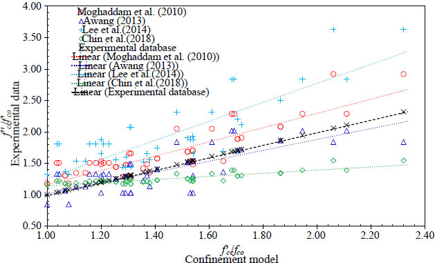
The variation of pre-tension level showed a strong correlation on the confining stress path, thereby, the axial stress-strain behavior of confined concrete [18]. The authors tested four specimens with the pre-tension strain of 0.00035 and 0.00220. For lower stiffness of the confining device due to lower pre-tension strain, the confining stress path was dissipated and vice versa. Concerning the high-strength concrete [20], strength improvement had been found in steel strip confined concrete with square sections that generated high-stress concentration at corners. The stress-strain behavior of steel strip confined concrete shows more significant improvement in peak compressive strength, strain, and ductility on normal-strength concrete than on high-strength concrete. The enhancement is in line with the increase in steel strip thickness and number of layers but in contrast to the increase in steel strip spacing. The previous studies presented above also proposed confined concrete models for predicting the strength behavior of steel strip confined concrete. Fig. (1) compares the experimental results and prediction using the proposed model.
From the previous studies presented in this section, several key points can be drawn:
• A single layer of steel strip exhibited good confinement capabilities for cylinder concrete without reinforcement, and it is necessary to explore the capabilities of slender reinforced concrete.
• The pre-tension mechanism proposed in previous studies can potentially enhance the stress-strain behavior of concrete. Therefore, the magnitude of the steel strip pre-tension force as active confinement in slender concrete is essential for the retrofitting system. The initial clamping pressure with bolt tightening is believed to exhibit a similar potential as active confinement.
• Placing an active confinement device in a parallel pattern possibly increases stress concentrations in specific paths along the height of the concrete. Hence, a staggered scheme of steel strip confining devices can reduce stress concentration.
• During service load, the concrete column is inseparable from the load eccentricity. No study has examined the behavior of slender concrete confined with thin steel sheets subjected to eccentric axial compression loads.
2.3. Experimental Works
The experimental investigation focuses on two eccentrically loaded RC column specimens: a conventional RC column (UC25) and a strengthened RC column (C25). The load eccentricity for both specimens is set to 25 mm. A steel sheet with a diameter-to-thickness ratio of 110 is utilized in the strengthened column. The compressive strength of the concrete is determined through a concrete cylinder test conducted at 28 days, yielding a value of 26.1 MPa. The conventional RC column is reinforced with six 6-mm longitudinal bars without transverse reinforcement. The specimens have a length of 600 mm and a diameter of 110 mm, resulting in a slenderness ratio (L/D) of 5.45. Uniaxial tensile tests were performed to obtain the material properties, including the strength of the thin steel sheet, bolts, and reinforcing bars. The results of these tests are presented in Table 1.
| Parameter |
Sheet SNI 2052-2017 |
Bar ASTM A325 |
||
|---|---|---|---|---|
| 1 mm | 2 mm | M8 | ∅6 | |
| fy (MPa) | 180.1 | 283.5 | 534.1 | 451.6 |
| fu (MPa) | 275.4 | 330.1 | 664.6 | 621.1 |
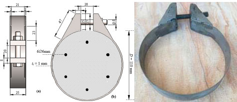
Fig. (2) depicts the configuration of the thin steel sheets employed as the external confinement device. The height of each thin steel sheet measures 25 mm, while the clear distance between the extended plates is set at 15 mm. The extended plate includes a stiff thin plate design to ensure minimal deformation, and the fastened bolt facilitates the transfer of clamping force from the bolt to the extended plate and subsequently to the concrete. Specifically, an M8 bolt fastener with a grade of 8.8 is utilized for this purpose.
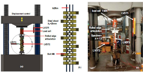
Fig. (3a) illustrates the experimental setup for the eccentrically loaded specimen. The bolt was tightened from a snug-tight condition to generate the initial confining pressure until it completed one full rotation. Specially designed end plates and a roller were positioned at the top and bottom faces of the concrete specimen, allowing for eccentric axial compression. As depicted in Fig. (3a), these components were allowed to rotate. In Fig. (3b), the clear vertical gap between the thin steel sheets is 15 mm. Both ends of the specimen were embedded approximately 50 mm into the plate sleeve to prevent failures near the loading supports.
Two LVDTs (Linear Variable Differential Transformers) were placed at the moving segment of the testing machine to measure vertical displacements. One LVDT was positioned at the mid-span of the specimen on the outer compression face to measure the increase in lateral deformation during loading. Additionally, a TML 1.0 MN load cell was installed at the top of the loading platen to measure the applied vertical force on the specimen. It is important to note that two thin steel sheets were installed at both ends for the conventional RC column to prevent localized failure. The sample was subjected to monotonic loading until failure using displacement control.
2.4. Numerical Study
This section focuses on the numerical simulation conducted using the 3D-NLFEA (Three-Dimensional Nonlinear Finite Element Analysis) package [3, 22, 23]. In this study, the numerical model considers a single concrete strength that corresponds to the tested specimen's concrete strength. The thickness of the thin steel sheet incorporated in the simulation is 1 mm. The numerical analysis investigates various load eccentricities, namely 0, 5, 10, 25, 35, and 50 mm, denoted as C0, C5, C10, C25, C35, and C50, respectively. These eccentricities are utilized to evaluate their impact on the behavior and performance of the strengthened column.
2.4.1. Finite Element Model and Boundary Conditions
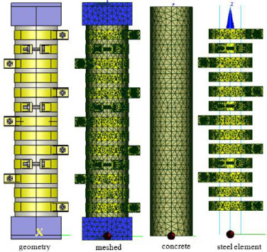
Fig. (4) illustrates the model geometry of the C25 column, which was prepared using SALOME 9.9.0. The model's geometry is meshed with tetrahedral elements, as depicted in Fig. (4). The global mesh size of the elements was set to range from 0.5 mm to 15.0 mm to ensure an accurate representation of the transition between different parts. The bar was modeled using embedded truss elements and meshed with a maximum size of 5 mm. The meshed element of the C25 column consisted of a total of 36,974 nodes, 162,886 solid elements, and 720 rebar elements. Zero-thickness elements were employed to simulate the concrete and steel material interface. Additionally, two thick steel plates were included at both ends of the model to reduce stress concentrations resulting from the knife-edge load displacement control. The bottom plate was fixed in all directions, while the top plate was fixed in two horizontal directions, establishing the necessary boundary conditions for the analysis.
2.4.2. Material Constitutive Model
The concrete material in the analysis is modeled using the multi-surface plasticity fracture model developed by Piscesa et al. [3, 22-24]. The concrete compressive strength used in the model is 26.1 MPa. The Poisson's ratio of the concrete material is set to 0.2, while the elastic modulus is assigned as 20,152 MPa. Regarding the steel material, including the steel plate, bolts, and reinforcing bar, the J2 metal plasticity or Von-Mises criterion [25] is utilized. The yield strength values for these materials can be found in Table 1. In the 3D-NLFEA analysis, the steel reinforcing bar can be modeled using either a bilinear stress-strain model [22] or a custom stress-strain model. The yield strength values for these materials can be found in Table 1. In the 3D-NLFEA analysis, the steel reinforcing bar can be modeled using either a bilinear stress-strain model [22] or a custom stress-strain model.
2.4.3. Loading Sequence
In the analysis, two loading stages were simulated. In the first stage, the tightening of the bolts was modeled by applying an axial strain shortening equivalent to a tightening length of Δt = 0.1 mm, effectively closing the 20 mm gap between the jaws of the steel sheet clamp.
The shortening strain required to generate a bolt tightening of 0.1 mm was divided into ten steps, each applying an incremental conjugate displacement. The value of the incremental shortening strain per step was determined to be 0.0005. In the second loading stage, eccentric loading was applied using a full displacement control method. The incremental conjugate displacement was applied at the eccentric loading edge. It is important to note that in the experimental test, only the snap-through response of the load-deformation curve was observed. Therefore, utilizing the full displacement control method is deemed sufficient to capture all the load-deformation behavior of the eccentrically loaded column, as observed in the test.
3. RESULTS AND DISCUSSION
3.1. Experimental Results
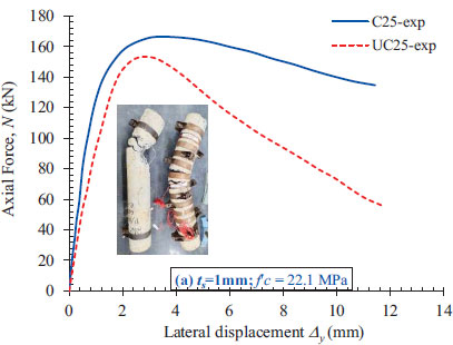
Fig. (5) presents a plot illustrating the relationship between the applied load and the lateral load for the conventional RC column and the strengthened RC column utilizing the proposed confinement mechanism. The photograph accompanying Fig. (5) represents the columns after failure, further highlighting the consequences of the applied loads and the resulting failure patterns. In terms of failure location, it is anticipated to occur at the mid-height of the specimen, as this region experiences the highest compressive and tensile stresses. The failure pattern observed at the weakest section is primarily attributed to concrete crushing on the compression side and crack opening displacement on the tension side.
During the initial loading stage of the UC25 column, no visible cracks were observed until the measured axial load reached approximately 90% of the ultimate load. Subsequently, tensile cracks gradually formed, widened, and propagated as the applied displacement increased. Notably, the failure location for the UC25 column shifted upwards from the mid-height of the specimen. In contrast, localized failure in the C25 column occurred precisely at the mid-height of the column. As depicted in Fig. (5), the concrete spalled due to crushing on the compression side, while wide crack openings were evident on the tension side for the UC25 column. However, for the C25 column, only crack openings on the tension side were observed. This observation indicates that thin steel sheets can effectively confine the concrete core, preventing outward dilation on the compression side and mitigating concrete crushing and spalling. Towards the end of the loading stage, two crack openings were observed in the region between the steel sheet (near sheet #7) of the C25 column. The crack widths measured 18.4 mm and 21.1 mm, respectively.
During the test, the maximum applied load (Pu) for the UC25 column was 153.37 kN, resulting in a vertical displacement (∆h) of 2.47 mm. In contrast, the C25 column exhibited a higher maximum applied load of 166.42 kN and a vertical displacement of 3.43 mm. The load-carrying capacity of the C25 column demonstrated an increase of 8.51% compared to the UC25 column indicating that the proposed confinement mechanism using the thin steel sheets effectively enhanced the load-carrying capacity of the strengthened column.
3.2. Results of Numerical Study
3.2.1. Load-deformation Response
Fig. (6a) shows the axial force at the eccentric loading point as a function of the lateral displacement or additional eccentricities at the mid-height of the column. For column C25, the predicted peak load using the numerical simulation (3D-NLFEA) was higher than the test result. The model accurately predicted the initial stiffness and the softening behavior indicating that the primary input for the concrete material properties and modeling assumptions was correct. The axial stress and lateral strain at the extreme compression side within the mid-height of the concrete model are plotted in Fig. (6b). In Fig. (6b), the axial stress in the extreme compression fiber was found to be increased as the load eccentricities increased.
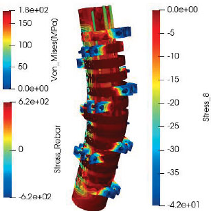
3.2.2. Failure Mode
Fig. (7) depicts the failure mode of the eccentrically loaded column, characterized by localized failure at the mid-height of the column. This observation aligns with similar findings reported previously [26]. The load eccentricities introduce a second-order effect, wherein the axial load-carrying capacity of the RC column increases as the load eccentricities increase. In Fig. (7), it can be observed that the concrete located at the extreme compression face is extruded outwards. The lateral volumetric expansion of the concrete core causes this outward displacement. The confinement provided by the thin steel sheets helps to prevent excessive outward dilation and maintain the structural integrity of the column.

The strength enhancement factor (ξ) was introduced to evaluate the columns' strength and ductility. The strength enhancement factor represents the ratio of the enhanced local stress in the compression region compared to the unconfined concrete compressive strength. The expression for the strength enhancement factor (ξ) is:
 |
(1) |
The stress tensor generated at the corresponding nodes from the 3D-NLFEA simulation was utilized to obtain the enhanced local stress in the compression region.
3.2.3. Strength Enhancement Factor and Ductility
The raw sensor data from the simulation were transformed into principal stress using the stress invariants [27].
The numerical simulation results evaluated at the mid-height section of the column, collected at peak load conditions, are presented in Table 2. Table 2 shows that the strength enhancement factor (ξ) in the localized compression area increased as the load eccentricity increased. The averaged confining pressure was relatively consistent across different load eccentricities. These findings suggest that the external confinement mechanism effectively enhanced the local stress in the compression region, increasing the strength of the strengthened column.
The confining pressure of each circumferential node was considered to determine the confining pressure (fr) within the mid-height section. The confining pressure values from all nodes within the compression side of the section were averaged at the peak load. This averaging process estimated the overall confining pressure on the concrete core in the compression region.
The ductility of a slender circular column is influenced by various factors, including the strength of the concrete core, the arrangement of longitudinal and transverse reinforcing bars, and premature cover spalling, especially in high-strength concrete. The presence of internal and external confinement can significantly enhance the ductility of the reinforced concrete (RC) column. An I10 ductility index, specified in AS3600-2018 [28], was utilized to evaluate the improvement in ductility resulting from the proposed confinement mechanism. The I10 ductility index quantifies the area beneath the load-nominal strain curve, considering a nominal strain value 5.5 times the yield nominal strain [29]. However, due to the unequal confinement resulting from the staggered pre-tensioned thin steel tube, obtaining a consistent nominal strain was challenging in this study. Instead of using axial strain to evaluate the column's ductility index, this study employed the conjugate displacement as a better reference to compare the effect of the proposed confinement mechanism. Table 2 presents the results, indicating that the column model with lower eccentricity exhibited a lower level of ductility than the model with higher eccentricity, concluding that higher eccentricity in load application can improve the column's ductility. The test results show that the proposed confinement mechanism can improve the ductility of the column from 7.17 (UC25) to 8.52 (C25).
| No. | ID | f'c | e | ts | hs | Δpeak | Ppeak | εpeak | σpeak | ξ | fr | I10 |
|---|---|---|---|---|---|---|---|---|---|---|---|---|
| MPa | mm | mm | mm | mm | kN | mm/mm | MPa | - | MPa | - | ||
| 1 | C0 | 26 | 0 | 1.00 | 25 | 0.820 | 391.8 | 0.00159 | 32.81 | 1.26 | -1.832 | 9.08 |
| 2 | C5 | 26 | 5 | 1.00 | 25 | 1.480 | 327.71 | 0.00315 | 35.72 | 1.37 | -1.687 | 8.13 |
| 3 | C10 | 26 | 10 | 1.00 | 25 | 1.520 | 282.06 | 0.00487 | 34.77 | 1.34 | -1.679 | 8.20 |
| 4 | C25(C) | 26 | 25 | 1.00 | 25 | 1.440 | 175.02 | 0.00484 | 37.90 | 1.46 | -1.721 | 8.52 |
| 5 | C25(UC) | 26 | 25 | 1.00 | 25 | 1.604 | 148.93 | 0.00198 | 17.05 | 0.66 | - | 7.17 |
| 6 | C35 | 26 | 35 | 1.00 | 25 | 1.680 | 130.91 | 0.00503 | 35.12 | 1.35 | -1.696 | 8.69 |
| 7 | C50 | 26 | 50 | 1.00 | 25 | 2.200 | 89.01 | 0.00468 | 41.10 | 1.58 | -1.633 | 9.13 |
3.2.4. The Behaviour of the Thin Steel Sheet
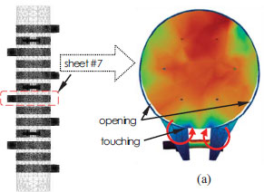
During the first load sequence, the mechanical behavior of the steel sheet was observed by applying initial confining stress through bolt shortening within the 3D-NLFEA. Fig. (8) illustrates the deformation of the steel sheet during this load sequence, which involved applying a small pre-tension force to the bolts.
As depicted in Fig. (8), there was an opening between the concrete and steel sheet during the bolt-tightening sequence. Additionally, the radial stress resulting from bolt tightening caused a stress concentration in the concrete core, which was approximately 46.6% higher than the adjacent zones, as shown in Fig. (8b). The stress concentration generated a moment at the touching zone and led to the rotation of the steel sheet. Consequently, the opening and uneven distribution of confining stress to the concrete column occurred. Thus, the bolt-tightening process created unequal initial confining pressure on the concrete core. The simulation of the C25 column showed that at the end of the second loading sequence, the steel sheet had reached the yield condition, with Von Mises stress reaching 180 MPa, as shown in Fig. (8b), indicating that the steel sheet experienced yielding, suggesting its contribution to the confinement of the concrete column.
3.2.5. P-M Interaction Curve
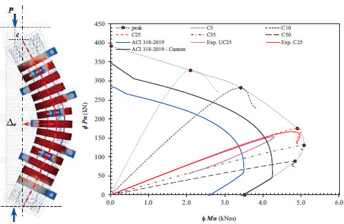
Fig. (9) illustrates the P-M curve for the modeled specimen using sectional analysis based on ACI 318-19 (or equivalent to SNI 2847-2019) and a series of eccentrically loaded columns with varying load eccentricities. In this analysis, the bending moment of the column is calculated by considering additional eccentricities (Δecc) that reflect the second-order effects in the eccentrically loaded column. The expression used to calculate the bending moment is as follows:
 |
(2) |
Fig. (9) demonstrates that the strength enhancement envelope (P-M curve) for the strengthened RC column showed a significant increase compared to the original. The nominal capacity of the code-generated P-M curve based on ACI 318-2019 was relatively lower due to considerations such as reduced concrete compressive strength (85%) to account for size effects and different curing conditions compared to the concrete cylinder. However, the reinforcing bar may achieve strain-hardening strength during loading. Considering this possibility and not reducing the concrete compressive strength, the P-M curve obtained from the sectional analysis was plotted with the label “ACI 318-2019 - Custom.” As depicted in Fig. (9), the custom P-M curve closely resembled the tested RC column with a 25 mm load eccentricity. The slightly higher moment observed in the test can be attributed to the second-order effects, which were not considered in the sectional analysis.
CONCLUSION
This paper investigates the behavior of eccentrically loaded circular RC columns strengthened with circular thin steel sheets. Both experimental testing and numerical analysis were conducted. The failure mode for the UC25 column involved concrete crushing in the compression face and tensile crack opening displacement in the tension side. In the case of the C25 RC column, the thin steel sheet restrained the concrete from crushing in the compression face. Based on the observations from the test results, it can be concluded that the proposed confinement mechanism effectively prevents concrete crushing in the compression face, leading to increased load-carrying capacity and ductility of the column.
The experimental observations and numerical analysis revealed stress concentration and a small opening between the concrete and the sheet in the tightening zone. The numerical investigation using 3D-NLFEA, which employed a plasticity-fracture model, accurately predicted the behavior of the eccentrically loaded RC column strengthened with a thin steel sheet and initial confining pressure generated from bolt tightening.
In terms of performance enhancement, the strength of the strengthened RC column increased from 153.37 kN to 166.42 kN, representing an 8.51% increase in strength. Regarding ductility enhancement, the I10 ductility index of the column with 25 mm load eccentricities increased from 7.17 (UC25 RC column) to 8.52 (C25 RC column), corresponding to an 18.82% increase in ductility. Further investigations into different tightening levels by a careful partial strapping mechanism to reduce stress concentration throughout the confined zone and to prevent openings between the steel sheet and concrete surface during the confinement process in future studies would be valuable for evaluating the performance of the proposed confinement mechanism. The code-generated P-M curve was conservative, suggesting improvements in the stress-strain model used in the sectional analysis should be considered in future investigations.
AUTHORS' CONTRIBUTIONS
SIY, BP, and PS prepared the conceptualization of the manuscript, SIY and BP prepared the methodology and BP and SIY prepared the FEM setup. SIY and BP carried out validation with the available test result, SIY prepared the manuscript, BP reviewed the draft and PS provided supervision and re-reviewed the draft. All authors read and agreed to the published version of the manuscript.
LIST OF NOTATIONS
| D | = column section diameter |
| Ec | = Modulus elasticity of concrete |
| e | = load eccentricity |
| f'cc | = confined compressive strength of concrete |
| f'c | = characteristic compressive strength of concrete |
| fy | = yield strength of steel material |
| fr | = average confining pressure |
| fu | = ultimate strength of steel material |
| hs | = width of steel sheet |
| L | = column length |
| le | = slenderness limit |
| M | = moment capacity of the column |
| P | = axial capacity of the column |
| Ppeak | = maximum applied load |
| ts | = thickness of steel sheet |
| Δecc | = additional eccentricity |
| Δh | = horizontal displacement |
| Δpeak | = horizontal displacement at peak axial load |
| Δt | = tightening length |
| εp | = lateral strain at peak load |
| σpeak | = axial stress corresponding to peak axial load |
| ν | = Poisson's ratio of concrete |
| ξ | = strength enhancement factor |
CONSENT FOR PUBLICATION
Not applicable.
AVAILABILITY OF DATA AND MATERIALS
The data and supportive information are available within the article.
FUNDING
None.
CONFLICT OF INTEREST
The authors declare no conflict of interest financial or otherwise.
ACKNOWLEDGEMENTS
The first author would acknowledge the support of Lembaga Pengelola Dana Pendidikan (LPDP)– Kementerian Keuangan Republik Indonesia and Yayasan Pendidikan Tinggi Nusa Nipa and technical support provided by the Laboratory of Concrete, Advanced Material and Computational Mechanic, Department of Civil Engineering, Sepuluh Nopember Institute of Technology, Indonesia.

