All published articles of this journal are available on ScienceDirect.

Performance of Soil-bearing Spread Footings Supporting Highway Structures
Authors Info & Affiliations
Abstract
Background
Soil-bearing spread footings (SBSF) are emerging as an increasingly attractive option for supporting highway structures. SBSF offers numerous benefits compared to deep foundations, including cost-effectiveness, accelerated construction, straightforward design, environmentally friendly characteristics, and reduced maintenance requirements.
Objective
The primary objective of this study is to assess the performance of highway structures that SBSF supports at four specific locations in Ohio. The findings from this assessment will serve as valuable recommendations for the future application of spread footings while identifying potential usage constraints.
Methods
The project team conducted a comprehensive review of documented performance data, assessed the effectiveness of existing footings, and compared these assessments against established structural performance criteria. Additionally, the team analyzed calculated settlements, provided an estimate of acceptable structural settlement, compared measured settlements with predicted values, and examined the relationship between performance and soil conditions.
Results
The data gathered, and field assessments conducted at all four sites encompassed in this investigation affirm that SBSF structures function as designed, displaying no signs of settlements or cracks associated with rideability. Both measured and calculated settlements fall within acceptable tolerances. While all structures exhibited acceptable levels of differential settlement, one encountered a differential settlement of approximately 54 mm between substructures, attributed to cohesive soil (A-6) in deeper layers.
Conclusion
SBSF structures were constructed by the manuals and guidelines established by the Ohio Department of Transportation (ODOT) and exhibited satisfactory performance. This paper also offers recommendations for settlement monitoring methods and plan notes that should be incorporated into the Ohio Department of Transportation's practices.
1. INTRODUCTION
Spread footings placed on soil present several advantages in contrast to deep foundations. These advantages include cost-effectiveness, faster construction, simplified design, environmental sustainability, and decreased maintenance [1-4].
Shallow foundations are generally at least 30% more cost-effective than deep foundations and can support various civil engineering structures [5]. Foundations significantly contribute to the overall construction expenses of concrete bridges, typically accounting for 19 to 27% of the total bridge construction cost, depending on the construction method and bridge design system employed [6].
Spread footings are typically chosen when deep foundation installation is unfeasible, such as accommodating aquifers, underground structures like utilities, or obstructions below foundations. They also contribute to decreased noise, ground vibrations, and minimal impact on nearby structures. The construction of spread footings utilizes readily available materials and can be undertaken with simple equipment and a readily available workforce. This often results in a simpler and quicker construction process and more straightforward quality control than deep foundations. These advantages make the construction of spread footings conducive to a safe working environment and reduce claims [7].
In 2007, the Federal Highway Administration (FHWA) initiated a national survey of the geotechnical practices of state Departments of Transportation (DOTs) across the United States [8]. Survey responses were received from 44 states. The results highlighted the distribution of bridge foundation types considered by State DOTs, indicating approximately 24% for spread footings (11.5% on soils and 12.5% on rock) and 76% for deep foundations (56.5% driven piles and 19.5% drilled shafts). Based on this survey, the FHWA suggested that certain State DOTs could save time and costs by appropriately implementing spread footings on soils to support bridge construction.
Civil engineering professionals must document and disseminate data from case histories to advocate for the use of footings in highway structures while also reporting any shortcomings. A thorough understanding of the behavior of spread footing foundations concerning settlement and other factors under various loading and environmental conditions is critical for promoting their use in construction. Furthermore, additional validation of performance prediction methods through case histories contributes to the wider adoption of spread footing foundations [9].
Nevertheless, there is an inherent need for well-documented, comprehensive case histories that should be established and made accessible to bridge and geotechnical engineers to encourage their adoption. Despite the previous success of studies on shallow foundations, further research is warranted to evaluate the performance of spread footings in the context of highway bridge foundations. It should be noted that using spread footings may not be suitable or cost-effective under certain design conditions. These include instances involving deep, soft soil near the ground surface, high lateral loads (e.g., due to a significant earthquake), and sites with substantial scour or liquefaction depths [8].
The research in question identifies a notable gap in the current understanding of the performance of Soil-Bearing Spread Footings (SBSF) in supporting highway structures, particularly in the specific context of Ohio. While acknowledging the advantages of SBSF over traditional deep foundations, the study lacks a comprehensive evaluation of their performance in diverse soil conditions and environments. The regional specificity to Ohio raises concerns about the generalizability of the findings, and the study may benefit from a deeper analysis of factors influencing performance variations, a focus on long-term durability, and a comparative assessment with traditional deep foundations. Furthermore, providing more nuanced recommendations for different soil conditions would enhance the practical applicability of the research findings. Addressing these aspects would contribute to filling the research gap and providing a more comprehensive understanding of SBSF performance in real-world applications.
The distinctive contribution of this research lies in the comprehensive evaluation of the performance of Soil-Bearing Spread Footings (SBSF) in supporting highway structures, specifically conducted at four distinct locations in Ohio. This study addresses the growing significance of SBSF as an appealing alternative to deep foundations, emphasizing various advantages such as cost-effectiveness, accelerated construction, straightforward design, environmental friendliness, and reduced maintenance requirements.
2. METHODOLOGY
This study assesses the effectiveness of highway structures constructed on spread footings-bearing soils. The primary objective of this assessment is to identify any potential constraints and determine the future viability of these structures. To accomplish this research goal, the investigative team carried out the following tasks:
1. Examine the documented performance data.
2. Assess the performance of the existing footings and make comparisons with the performance criteria for bridges.
3. Analyze the collected settlement data.
4. Provide an estimation of the acceptable settlement for the structure at its foundation site.
5. Contrast the observed settlement with the predicted long-term settlement.
6. Evaluate the relationship between performance, soil conditions, and calculated bearing pressures.
3. LITERATURE REVIEW
Numerous methods have been developed to predict the behavior of spread footings, including bearing capacity and settlement estimation, using data from the standard penetration test (SPT) or the cone penetration test (CPT). These methods have been put forth by various researchers, including Hough [10], Alpan [11], Meyerhof [12], Terzaghi and Peck [13], D'Appolonia et al. [14], Peck and Bazaraa [15], Schmertmann [16], and Schmertmann et al. [17].
Sargand and Masada [18] conducted a comprehensive study involving instrumentation and monitoring the settlements of four bridges supported on spread footings in Ohio. Their investigation covered both construction stages and post-construction periods. Using field performance data, the researchers validated the design methods for spread footings as outlined in the AASHTO LRFD Bridge Design Specifications (2004). The study evaluated twelve settlement prediction methods based on the Standard Penetration Test (SPT) for footings on cohesionless or slightly cohesive soils. The analysis provided valuable insights into the application of spread footings for supporting highway bridge structures, including thoroughly examining cost comparisons between spread footings and piles. The research project's findings indicated that spread footings present a viable option for bridge foundations, and the AASHTO LRFD Bridge Design Specifications [19] were deemed satisfactory in this particular context.
In Ohio, five highway bridge construction sites had more than fifty spread footings where Sargand et al. [20] performed instrumentation and monitoring. These footings had an average settlement of 20 mm, ranging from 0.19 to 36 mm. The settling occurred about 70% before the deck was built. We did not see any serious problems with differential mobility. The small amount of data gathered in the six months following the bridge's opening showed that the additional settlement caused by the application of live loads ranged from 1.27 to 12.7 mm, with an average of 4.32 mm. A 25mm settlement was considered satisfactory.
Twelve spread footings were observed by Baus [21] to be settling at three locations for highway bridges in South Carolina. The overall displacement varied between 10.16 and 55.88 mm. He examined the differences between the six methods' forecasts and the highest settlement that could be measured in the field (Alpan [11], Hough [10], Meyerhof [12], Peck-Bazaraa [15], Buisman-De Beer [22], and Schmertmann methods [16, 17]). Baus concluded that Hough's [10] and Peck and Bazaraa's [15] approaches produced more accurate settlement forecasts.
In Washington, 148 bridges supported by spread footings on compacted fill were surveyed by DiMillio [23]. Every bridge was in excellent shape and had no operational or safety issues. These bridges could withstand differential settling of 25.4 mm to 76.2 mm, according to DiMillio, without experiencing significant strain. He estimates spread footings are 50–60% less costly than pile foundations.
In their study, Moulton et al. [24] investigated the permissible movement of bridges by analyzing movement and damage data from 204 bridges supported by either spread footings or piles. The findings indicated that abutments supported on piles exhibited an average vertical movement of 69 mm, while those supported on spread footings showed a slightly smaller average of 61 mm. Regarding horizontal movement, pile-supported abutments recorded an average of 142 mm, whereas spread footing-supported abutments had a slightly higher average of 155 mm. The research concluded that a higher incidence of movement was observed in abutments on spread footings compared to those on piles. However, abutments founded on piles demonstrated larger ranges and marginally greater average vertical and horizontal movements than those founded on spread footings. These results suggest that opting for pile foundations does not necessarily ensure that abutment movements consistently remain within acceptable limits, particularly for rested abutments on fills.
4. RESEARCH SITES
The research gathered and analyzed information based on data sourced from Report No. FHWA/OH-2021-04, specifically Division of Engineering Research on Call Agreement 31796 Task 7, focused on the Service Evaluation of Highway Structures with Soil-Bearing Spread Footings [25]. In this section, we provide background information and data for four distinct sites (MAH-680-2.83, CUY-77-14.35, FAI-33-13.09, and CUY/SUM-271-00.00/14.87), where spread footings were under continuous monitoring during various phases of construction. Surveys were conducted between October 13 and 14, 2020.
5. MAH-680-2.83 Bridge
The structure identified as MAH-680-0283 is a four-span bridge carrying Vestal Road (Rd) over Interstate 680 (IR-680) in Mahoning County, situated in the northwestern region of Youngstown, Ohio. In 2016, a significant rehabilitation effort was undertaken on this bridge, involving the removal of the existing superstructure, three piers, and an elevation adjustment of the existing abutment seats. New spread footings were specifically constructed for the piers, while the existing spread footings at the abutments were retained. Painted steel girders and a reinforced concrete deck characterize this four-span continuous design bridge. The rehabilitation project included the installation of new semi-integral abutments and bearings and the construction of new cap and column piers, all founded on spread footings. The footing width for Piers 1 and 3 measures 4.4 meters, while Pier 2 has a slightly narrower footing width of 2.74 meters.
The site's stratigraphy reveals hard silt and clay (A-4) near the ground surface up to an elevation of about 284 m, where a dense sand and gravel or sand layer (A-1-b, A-3) 1.5 to 4.5 m thick was encountered. Below this layer are another hard layer of silt/ sand mixture (A-4) and a hard silt layer beneath it. Groundwater was not encountered. The bottom footing elevations for piers 1, 2, and 3 are 286.5 m, 286.2 m, and 285.6 m, respectively. The average SPT N value remained relatively constant, around 50 below the foundation depth for all substructures.
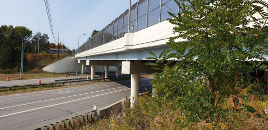
An on-site inspection was carried out on October 6, 2020, at the MAH-680-0283 bridge, focusing on the bridge deck and sidewalk to identify any cracking or settlements. Fortunately, no evidence of settlements or cracking was discovered. The piers were found to be in satisfactory condition with no observed settlement. During the inspection, it was noted that one of the PVC pipes above the settlement pins was broken at ground level. The current spread footing foundation of the bridge functions as intended, exhibiting no signs of settlement. Refer to Fig. (1) for an image of the MAH-680-0283 bridge.
In a recent survey, various pier footings underwent comprehensive monitoring. The spread footings of the piers were observed at various stages, including after the concrete pouring for the footings, both before and after beam placement, following the concrete pouring for the deck, and upon the completion of the entire project. The monitoring data for both the right and left monuments of each pier are detailed in Table 1.
After the project, the maximum recorded settlement amounted to approximately 13 mm. However, in a recent assessment, the highest settlement measured was around 19 mm. Negative values were observed due to permissible elevation reading errors, indicating no settlement. Over approximately four years, there was minimal change in settlements, and they remained well within acceptable limits for the given span lengths. The ratio of measured settlement to girder length was 0.00067, which is significantly below the acceptable limit of 0.004, as established by Felix Yokel [26].
Certain substructure units displayed negative settlements, a phenomenon potentially attributed to alterations in the benchmark or measurement errors. It's noteworthy that surveying accuracy is confined to the nearest 3.175 mm. This specific data pertains to CUY-77-14.35 Walls.
The project encompasses the construction of four cast-in-place (CIP) concrete cantilever walls (Walls 1, 2, 3, and 4) and replacing Bridge No. CUY-1433 L&R over I.R. 490 and Ramps, located south of Cleveland, Ohio. The bridge features a three-span continuous steel hybrid girder composite with a reinforced concrete deck supported by reinforced concrete piers and semi-integral abutments. The foundation of the bridge relies on 406 mm cast-in-place reinforced concrete piles. Settlements were monitored for Walls 1 and 4, the left rear abutment wing wall (Wall 2), and the right forward abutment wing wall (Wall 3).
| Stage | Elevation of Left Monument (m) | Elevation of Right Monument (m) |
Date | ||||
|---|---|---|---|---|---|---|---|
| Pier 1 | Pier 2 | Pier 3 | Pier 1 | Pier 2 | Pier 3 | ||
| After Footings Poured | 287.722 | 287.497 | 286.808 | 287.707 | 287.466 | 286.762 | 2016-05-31 |
| Before Beams | 287.710 | 287.487 | 286.808 | 287.704 | 287.466 | 286.762 | 2016-06-28 |
| After Beams | 287.707 | 287.484 | 286.805 | 287.707 | 287.463 | 286.759 | 2016-07-28 |
| After Deck Pour | 287.710 | 287.487 | 286.808 | 287.713 | 287.466 | 286.765 | 2016-10-05 |
| Project Completion | 287.710 | 287.484 | 286.805 | 287.707 | 287.466 | 286.765 | 2016-11-12 |
| This Task | 287.710 | 287.478 | 286.811 | 287.713 | 287.469 | 286.768 | 2020-10-13 |
| Measured Sett. at Project Completion (mm) | 12.00 | 13.00 | 3.00 | 0.000 | 0.000 | -3.00 | - |
| Measured Settlements under this Task (mm) | 12.00 | 19.00 | -3.00 | -6.00 | -3.00 | -6.00 | - |
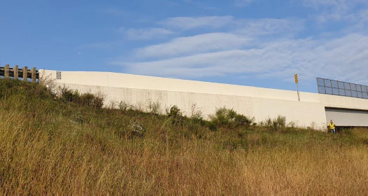
The footing width for Walls 1 and 4 is 3.8 m and 3 m, respectively, while the footing width for Walls 2 and 3 is 4.26 m. On October 6, 2020, a site visit was conducted. Inspection of the cantilevered cast-in-place concrete wing walls revealed vertical alignment without any noticeable leaning or sliding. The foundation of the bridge retaining walls, founded on spread footing, was confirmed to function as designed. Refer to Fig. (2) for an illustration of the Right Forward Abutment Wing Wall (Wall 3).
6. CUY-77-14.35 Soil Profile
6.1. Wall 1 (I.R. 77 Sta. 72+19.25 to Sta. 74+20.54)
Fill was encountered below the pavement to a depth of 7.77 m and consisted of medium-dense to hard sandy silt (A-4) and dense coarse and fine sand (A-3). Natural soils were encountered below the fill to the termination depth of 12.2 m and consisted of medium-dense, fine sand (A-3). Groundwater seepage was not encountered. The average SPT N value ranged from 23 to 46 under the wall footing.
6.2. Wall 4 (I.R. 77 Sta. 80+34.56 to Sta. 82+71.00)
Fill was encountered below the pavement to a depth of 7 m and consisted of medium-dense sandy silt (A-4) and dense gravel with sand (A-1-b). Natural soils were encountered below the fill to the termination depth of 12.2 m and consisted of soft to medium-stiff silt and clay (A-6), medium-dense to dense coarse and fine sand (A-3), and dense, fine sand (A-3). No groundwater seepage was encountered. The average SPT N value ranged from 15 to 45 under the wall footing.
6.3. Bridge No. CUY-1433 L&R over I.R. 490 and Ramps Wing Walls
6.3.1. Left Rear Abutment wing wall-Boring BB-106 (Wall 2)
Beneath the pavement, an observed material categorized as fill extended to a depth of 9.75 m. This fill included medium-dense to very-dense gravel with sand (classified as A-1-b) and dense coarse and fine sand (classified as A-3). Below the fill, natural soils were encountered down to a termination depth of 27.4 m, consisting of medium-dense fine sand (A-3), medium-dense to very-dense coarse and fine sand (A-3), stiff to very-stiff silt (A-4), and medium-stiff to stiff silty-clay (A-6). Groundwater seepage was noted at a depth of 16.3 m, with groundwater at 17.8 m. The average SPT N value under the wall footing ranged from 15 to 44.
For the right forward abutment wing wall (Wall 3), material visually identified as fill was found beneath the pavement at a depth of 9.75 m. This fill consisted of dense sandy silt (classified as A-4), dense silt (A-4), medium-dense fine sand (A-3), and dense to very-dense coarse and fine sand (A-3). Natural soils were present below the fill, extending to the termination depth of 27.4 m. These natural soils comprised medium-dense to very-dense fine sand (A-3), medium-stiff to dense sandy silt (A-4), and dense silt (A-4). Groundwater seepage was noted at a depth of 17.8 m, and water was observed at a depth of 20.9 m upon completion of the drilling. The average SPT N value under the wall footing varied from 14 to 41.
7. CUY-77-14.35 Settlement Monitoring Data
The monitoring of spread footings occurred at two key stages: once after the concrete was poured into the footings and again upon the completion of the project. Following these stages, a recent survey was undertaken to assess the footings. Table 2 presents the recorded monitoring data for the monuments of the left rear abutment wing wall (Wall 2) and the right forward abutment wing wall (Wall 3). Measured settlements after the project were approximately 6.0 mm for both Walls 2 and 3.
In the recent survey, the maximum measured settlement recorded was about 37 mm for Wall 2 and 18 mm for Wall 3. It's noteworthy that settlements generally remained stable, except for Wall 2, monument 2, where a notable change was observed.
| Stage | Elevation (m) | Date | |||
|---|---|---|---|---|---|
| Left Rear Abutment Wing Wall (Wall 2) | Right Forward Abutment Wing Wall (Wall 3) | ||||
| Monument-1 | Monument-2 | Monument-1 | Monument-2 | ||
| 22+91.63,19 m LT | 22+74.98,19 m LT | 24+19.2, 19 m RT | 24+34.64, 19 m RT | ||
| After Footing, Concrete Placed | 205.325 | 205.338 | 207.380 | 207.383 | N. A |
| Project Completion | 205.319 | 205.332 | 207.374 | 207.377 | N. A |
| Recently, this Task | 205.319 | 205.301 | 207.362 | 207.368 | 2020-10-13 |
| Measured Sett. at Project Completion (mm) | 6.00 | 6.00 | 6.00 | 6.00 | - |
| Measured Settlements under this Task (mm) | 6.00 | 37.00 | 18.00 | 15.00 | - |
The recorded monitoring data for the monuments of Walls 1 and 4 is detailed in Table 3. Upon project completion, the maximum measured settlement was approximately 3 mm for both Walls 1 and 4. In a recent assessment, settlements for Wall 1 ranged from 3 to 6 mm, while Wall 4 experienced measured settlements ranging from 125 to 195 mm. Notably, settlements for Wall 1 did not exhibit significant changes. However, Wall 4 encountered substantial settlements attributed to a 0.5 to 1.0 m layer of soft to medium-stiff silt and clay (A-6) immediately beneath the fill material at an elevation of 203 m. This layer is situated 3.25 m below the bottom of Wall 4 footing. Although the wall was inspected and found to be vertically plumb with no signs of leaning or sliding, the observed excessive settlements in Wall 4 suggest a potential issue with the benchmark.
8. FAI-33-13.09 Bridge
The FAI-33-1309 bridge, a four-span structure, is situated in Fairfield County, Ohio, west of Lancaster, carrying Delmont Road over U.S. Route 33, the Lancaster Bypass. This composite steel girder bridge features semi-integral abutments and cap and column-type piers resting on spread footings. The rear and forward abutments have a footing width of 2.4 meters, while all piers have a footing width of 4.25 meters.
| Stage | Elevation (m) | Date | |||
|---|---|---|---|---|---|
| Wall 1 | Wall 4 | ||||
| Monument-1 | Monument-2 | Monument-1 | Monument-2 | ||
| 22+32.81, 19.5 m RT |
22+60.96, 19.8 m RT |
24+49.72, 18.9 m LT |
24+94.64, 18.9 m LT |
||
| After Footing, Concrete Placed | 205.502 | 205.490 | 207.121 | 207.651 | N. A |
| Project Completion | 205.505 | 205.490 | 207.118 | 207.651 | N. A |
| Recently, this Task | 205.499 | 205.484 | 206.996 | 207.456 | 2020-10-13 |
| Measured Sett. at Project Completion (mm) | -3.00 | 0.000 | 3.00 | 0.000 | - |
| Measured Settlements under this Task (mm) | 3.00 | 6.00 | 125.00 | 195.00 | - |

A site visit was conducted on October 5, 2020, to assess various aspects of the FAI-33-1309 bridge. The inspection covered embankment slopes, roadway settlement at abutments, the condition of the concrete deck, and relative substructure orientation. Fortunately, no signs of settlements were detected, and the softness of the soils around the piers was attributed to drainage issues. Some PVC caps were missing or damaged, likely due to vandalism. The existing spread footing design for bridge foundations was functioning as intended. Refer to Fig. (3) for a visual representation of the FAI-33-1390 bridge.
Field exploration involved drilling five boreholes, following the specifications in the original geotechnical report. Each boring initially encountered a topsoil layer ranging from 0.1 to 0.3 meters deep. Below the topsoil, cohesive soils were consistently found, including stiff to hard silt and clay (A-6) and silty clay (A-6), with depths varying from 3.2 to 6.25 meters. Some of these soils contained organic components. Deeper layers in all five borings predominantly consisted of medium-dense to very-dense non-cohesive soils, such as gravel with sand (A-1-b), gravel with sand and silt (A-2-4), fine sand (A-3), and coarse and fine sand (A-3). Bedrock was encountered at depths ranging from 15 to 19 meters in boreholes B-30, B-31, and B-32. Silt (A-4) material was identified in boring B-34 at depths exceeding 15 meters. Bedrock, character- ized by medium-hard broken rock, was consistently reached in borings B-30, B-31, and B-32 at depths of 15 to 19 meters.
Sandstone has RQDs of between 30% and 50%. Water seepage was encountered at depths of between 2 and 5 m. The average SPT N value ranged from 12 to 50 below the foundation depth for all substructures.
Monitoring of spread footings took place at various critical stages, encompassing the pouring of the footings' concrete, both before and after beam placement, following the pouring of the deck's concrete, and upon the completion of the project. A recent survey of the footings was undertaken, and the recorded monitoring data for the monuments on the right and left of each pier is presented in Table 4. Settlement measurements, ranging from 9 mm to 30 mm, were documented upon the project's completion. In a recent assessment, settlements varied from 3 to 64 mm.
Over an approximately 19-year period, settlements remained largely consistent, except for the rear abutment. Notably, monuments at the right rear abutment and left and right pier 3 could not be located. In these instances, survey monument information was unavailable, prompting the survey crew to establish temporary benchmarks tied into two ODOT benchmarks through GPS observations.
9. CUY/SUM-271-00.00/14.87
The undertaking, identified as CUY/SUM-271-00.00/ 14.87 and CUY/SUM-480-29.58/00.00, encompasses the planning and construction of three new retaining walls designated as RW-1 (WS1), RW-2 (SW1), and RW-3 (WS2) in Summit/Cuyahoga Counties, Ohio. These retaining walls are part of the larger initiative involving the addition of two lanes, namely S-W and W-S, along the outer shoulders of IR-271 SB and N.B. between the Summit County Line and Alexander Road, situated south of Cleveland, Ohio. Settlement monitoring procedures have been applied specifically for RW-1 (WS1).
E.L. Robinson Engineering conducted a site visit on October 6, 2020. The inspection of the cantilevered cast-in-place concrete wall indicated vertical alignment with no observed leaning or sliding. The existing foundation of the retaining wall, designed with a spread footing, was verified to be operational as intended. Refer to Fig. (4) for a visual depiction of RW-1 (WS1).
| Stage | Elevation of Left Monument (m) | Elevation of Right Monument (m) | Date | ||||||||
|---|---|---|---|---|---|---|---|---|---|---|---|
| Rear Abut. | Pier 1 | Pier 2 | Pier 3 | F.R. Abut. | Rear Abut. | Pier 1 | Pier 2 | Pier 3 | F.R. Abut. | ||
| After Footings Poured | 278.929 | 274.143 | 274.738 | 273.601 | 279.145 | 278.956 | 274.165 | 274.744 | 273.656 | 279.163 | Between 06-05 and 07-12-2001 |
| Before Beams | 278.929 | 274.143 | 274.735 | 273.601 | 279.139 | 278.956 | 274.165 | 274.744 | 273.656 | 279.157 | 2001-10-19 |
| After Beams | 278.901 | 274.137 | 274.735 | 273.598 | 279.130 | 278.938 | 274.158 | 274.741 | 273.649 | 279.148 | 2002-03-21 |
| After Deck Pour | 278.910 | 274.131 | 274.731 | 273.595 | 279.136 | 278.932 | 274.152 | 274.735 | 273.646 | 279.154 | 2002-04-26 |
| Project Completion | 278.904 | 274.131 | 274.728 | 273.592 | 279.133 | 278.926 | N. Aa | 274.735 | 273.646 | 279.151 | 2002-08-05 |
| Recently, this Task | 278.865 | 274.146 | 274.735 | 273.741 | 279.121 | 279.063 | 274.155 | 274.738 | 273.835 | 279.145 | 2020-10-14 |
| Measured Sett. at Project Completion (mm) | 25.00 | 12.00 | 10.00 | 9.00 | 12.00 | 30.00 | N. Aa | 9.00 | 10.00 | 12.00 | - |
| Measured Settlements under this Task (mm) | 64.00 | -3.00 | 3.00 | -140b | 24.00 | -107b | 10.00 | 6.00 | -179b | 18.00 | - |

Field exploration was conducted using two boreholes, as the initial geotechnical report outlined. Both boreholes revealed predominantly cohesive subsurface soils consisting of a combination of fill materials and natural soils. In boring test B-007-1-13, the fill materials above the natural soils primarily comprised silt and clay (classified as A-6), with a thickness of approximately 2.5 meters. In boring test B-007-4-13, the fill materials were silty clay (also A-6) with a thickness of about one meter. Above the bedrock in boring test B-007-4-13, natural soils included sandy silt (A-4), silt, and clay (A-6), non-plastic sandy silt (A-4), as well as coarse and fine sand (A-3). Bedrock, identified as gray and severely to highly weathered shale, was encountered at an estimated depth of 18 meters in boring test B-007-4-13. The cohesive soils exhibited a range of consistencies from “medium-stiff” to “hard,” with an overall tendency towards “very-stiff.” The non-cohesive soils displayed relative density levels ranging from “dense” to “very dense.”
Table 5 presents the recorded monitoring data for RW-1 (WS1). Settlements were not collected for this recently constructed wall. Based on the provided data, the wall did not experience any settlements at the project completion.
It's important to highlight that the consolidation settlement calculation necessitates soil parameters not encompassed in the provided soil reports. The sole soil report furnishing such information is CUY/SUM 271-00.00/14.87 RW-1. Consequently, the settlement estimated for this wall is considered the total settlement.
10. COMPARISON BETWEEN ESTIMATED AND MEASURED SETTLEMENTS
In this section, we conduct a comparative analysis between the settlements estimated and the actual measurements. The measured settlement data is presented in the preceding sections of this report. We employ Hough's method to estimate the settlements of spread footings on cohesionless soil, as stipulated in section 10.6.2.4 of the AASHTO LRFD Bridge Design Specifications.
When estimating spread footing settlements, utilizing computational techniques grounded in laboratory testing, in-situ measurements, or a combination of both is essential. The choice of soil parameters for these computations should be made considering the ground's loading history, construction sequence, and the impact of soil layering.
| Stage | Elevation (m) | Date | |||||
|---|---|---|---|---|---|---|---|
| Sta. 988+69.80 | Sta. 988+91.3 | Sta. 989+16.69 | Sta. 989+33.60 | Sta. 989+50.51 | Sta. 989+75.88 | ||
| After Footing, Concrete is Placed | 316.550 | 316.527 | 316.550 | 316.536 | 316.530 | 316.379 | 1/8/2019 |
| After Wall Concrete is Placed and backfilled | 316.550 | 316.527 | 316.550 | 316.536 | 316.530 | 316.379 | 7/26/2019 |
| Project Completion | 316.550 | 316.527 | 316.550 | 316.536 | 316.530 | 316.379 | 10/30/2019 |
| Recent, this Task | N. Aa | N. Aa | N. Aa | N. Aa | N. Aa | N. Aa | - |
| Measured Sett. at Project Completion (mm) | N.A. | N.A. | N.A. | N.A. | N.A. | N.A. | - |
| Measured Settlements under this Task (mm) | N. Aa | N. Aa | N. Aa | N. Aa | N. Aa | N. Aa | - |
Hough's method (as described in Equations 1 and 2) offers a viable approach for estimating settlements in cohesionless soil. Typically, conservative settlement estimates can be obtained using either the elastic half-space procedure or Hough's empirical method [Hough, 10]. The Hough method presents distinct advantages over alternative approaches for estimating settlements in cohesionless soil deposits, particularly due to its explicit consideration of soil layering and the stress distribution beneath a finite-sized footing. In this method, the subsurface soil profile is divided into stratigraphic layers, typically to a depth approximately three times the width of the footing. Each layer should have a maximum thickness of about 3 meters.”
 |
(1) |
 |
(2) |
Where:
n= Number of soil layers within the zone of stress influence of the footing
∆Hi= Elastic settlement of layer i
Hc= Initial height of layer i
C'= Bearing Capacity Index, from Figure 10.6.2.4.2-1 of the AASHTO LRFD Bridge Specifications.
σo= Initial average effective stress of the subdivided soil layer.
∆σv= Vertical stress increase in the subdivided soil layer due to applied foundation load.
Table 6 compares estimated and measured settlements, encompassing evaluations after construction and recent measurements. It's worth noting that the average measured settlements were computed by taking the average of two monument readings for each footing, excluding the current measured settlements of FAI-33-13.09 pier 3 due to unavailable survey monument information.
It is evident from the analysis that Hough's method tends to over-predict immediate settlements, measured at the end of construction, and it also tends to overestimate current measured settlements for most of the footings. However, it is noteworthy that Hough's method significantly underestimates current measured settlements for certain footings with cohesive soil (A-6) layers, such as CUY-77-14.35 Wall 4 and the rear abutment of FAI-33-13.09. As a result, it becomes crucial to calculate long-term settlements when cohesive soils are present.
According to the Geotechnical report for CUY/SUM- 271-00.00/14.87, the recently completed Wall RW-1 (WS1) is anticipated to undergo an immediate 6 mm and consolidation settlements of 13 mm. The total settlement expected for the wall is 20 mm. The significance of consolidation settlements is underscored by cohesive soil beneath the wall's footing.
11. DIFFERENTIAL SETTLEMENTS BETWEEN SUBSTRUCTURES
Differential settlements between substructures are outlined in Table 7, depicting disparities after construction and current differentials based on a recent survey conducted in this study.
| Project | Structure | Estimated Settlements (mm) | Avg. Measured Settlements (mm) | (Estimated/ Measured) Settlement | ||
|---|---|---|---|---|---|---|
| End of Construction | Current Settlement | End of Construction | Current Settlement | |||
| MAH-680-2.83 | Pier 1 | 17.53 | 6.0 | 3.0 | 2.92 | 5.84 |
| Pier 2 | 12.70 | 6.5 | 8 | 1.95 | 1.59 | |
| Pier 3 | 11.94 | 0.0 | -4.5b | N.Aa | N.Aa | |
| CUY-77-14.35 | Wall 1 | 17.53 | -1.5b | 4.5 | N.Aa | 3.90 |
| Wall 4 | 13.72 | 1.5 | 160 | 9.14 | 0.09 | |
| LT. R.A.Wing Wall (Wall 2) | 22.61 | 6.0 | 21.5 | 3.77 | 1.05 | |
| RT. F.A.Wing Wall (Wall 3) | 19.30 | 6 | 16.5 | 3.22 | 1.17 | |
| FAI-33-13.09 | Rear Abut. | 23.11 | 27.5 | 64 | 0.84 | 0.36 |
| Pier 1 | 26.16 | 12 | 10 | 2.18 | 2.62 | |
| Pier 2 | 33.02 | 9.5 | 4.5 | 3.48 | 7.34 | |
| Pier 3 | 26.16 | 9.5 | N.Aa | 2.75 | N.Aa | |
| FR. Abut. | 18.54 | 12 | 21 | 1.55 | 0.88 | |
| CUY/SUM-271-00.00/14.87 | RW-1 (WS1) | 19.81 | 0.0 | N.Aa | N.Aa | N.Aa |
b negative settlement values, measurement error.
| Structure No. | Substructure | Ave. Measured Settlements (mm) | Differential Settlements between Substructures (mm) | |||
|---|---|---|---|---|---|---|
| End of Construction | Current Settlement | Two Substructures |
Based on End of Construction |
Based on Current Settlement | ||
| MAH-680-0283 | Pier 1 | 6.0 | 3 | Pier 1 and 2 | 0.5 | 5 |
| Pier 2 | 6.5 | 8 | Pier 2 and 3 | 6.5 | 12.5 | |
| Pier 3 | 0.0 | -4.5 | ---------- | ---------- | ---------- | |
| FAI-33-1309 | Rear Abut. | 27.5 | 64 | Rear Abut. and Pier 1 | 15.5 | 54 |
| Pier 1 | 12 | 10 | Pier 1 and 2 | 2.5 | 5.5 | |
| Pier 2 | 9.5 | 4.5 | Pier 2 and 3 | 0.0 | N. A | |
| Pier 3 | 9.5 | N.A | P3 and F.R. Abut. | 2.5 | N. A | |
| FR. Abut. | 12 | 21 | ---------- | ---------- | ---------- | |
For MAH-680-0283, at the end of construction, there were 0.5 mm of differential settlements between piers 1 and 2 and 6.5 mm between piers 2 and 3. According to recent settlement monitoring data, the structure underwent 5 mm differential settlement between piers 1 and 2 and 12.5 mm between piers 2 and 3. It is essential to highlight that these values fall within acceptable tolerances for settlement limits.
FAI-33-1309 demonstrated acceptable differential settlements ranging from 0.0 to 15.5 mm upon completion of construction. However, recent survey data monitoring settlements revealed differential settlements within the 5.5 to 54 mm range, with values at the piers lower than those observed at the end of construction. Notably, a recent recording indicated a differential settlement of 54 mm between the rear abutment and Pier 1, which can be attributed to the current settlements of 64 mm at the rear abutment. This variation may be influenced by cohesive soils, specifically stiff to hard silt and clay (A-6) and silty clay (A-6) at deeper layers beneath the rear abutment. Importantly, no indications of this differential settlement were observed at the rear abutment approach.
12. RESULTS AND DISCUSSION
1. Monitoring of spread footings was conducted at various stages of construction, including after pouring the footings' concrete, before and after the placement of beams, after pouring the concrete for the deck, and upon project completion. Recent surveys of the footings were also performed to obtain the final settlement values. Overall, the performance of the spread footings was satisfactory, with exceptions in areas where cohesive soils were present or when issues arose with survey benchmarks (such as settling or being unlocatable).
2. When there is significant variation in the corrected SPT-N value with depth over the depth of influence, and a single value cannot accurately represent the elastic modulus of sandy subsoil layers, it is recommended to utilize Hough's empirical settlement prediction method (as proposed in reference [10]).
3. The settlement of spread footings on cohesionless soil can be approximated using Hough's method, as outlined in section 10.6.2.4 of the AASHTO LRFD Bridge Design Specifications. The findings presented in this research substantiate the appropriateness of employing this method with a credible level of confidence.
4. It is crucial to emphasize that Hough's method tends to overestimate immediate settlements (measured at the end of construction) and over-predict current measured settlements for most of the footings. However, when footings are in regions with cohesive soil layers (A-6), Hough's method notably underestimates the current measured settlements. Hence, it is imperative to calculate long-term settlements when cohesive soil is present.
5. Upon the completion of construction, all structures demonstrated acceptable levels of differential settlements ranging from 0.0 to 15.5 mm. However, recent survey data monitoring settlements for one structure revealed differentials within the 5.5 to 54 mm range, with values at the piers lower than those observed at the end of construction. Notably, a recent recording highlighted a 54 mm differential settlement between the rear abutment and pier 1, attributed to the existing settlements of 64 mm at the rear abutment. This variation is likely influenced by cohesive soils, specifically stiff to hard silt and clay (A-6) and silty clay (A-6), at deeper layers beneath the rear abutment. Notably, no signs of this differential settlement were observed at the rear abutment approach.
6. The data collected at the study sites indicate that spread footings can effectively support highway structures, provided that the subsurface conditions are suitable, with the corrected SPT-N value exceeding 20 blows/0.3 m.
7. In this study, all structures experienced acceptable levels of differential settlements between substructures.
CONCLUSION
1. To gather and record historical performance data, it is crucial to establish reference markers for substructure units supported by spread footings. This data helps ensure that the foundation-bearing material performs as intended and is indispensable for enhancing spread footing reliability and evaluating settlement prediction methods' accuracy.
2. As part of the annual bridge inspection, conducting a yearly survey of reference markers for substructure units founded on spread footing foundations on soil is advisable. This practice serves the purpose of confirming the integrity of the spread footing design, investigating performance, and reviewing data for necessary actions. Measuring the elevation of the footings annually and maintaining a comprehensive database for tracking the long-term structural performance is highly recommended.
3. To ensure accurate future settlement readings, including the coordinates of markers and reference benchmarks in the as-built plans is essential.
4. Consider installing target points on substructures for more convenient elevation data collection. This proactive measure makes targets more visible and acts as a deterrent against vandalism. Simple optical survey equipment can be employed to measure relative settlement effectively.
5. When designing spread footings, it is of utmost importance to pay careful attention to subsurface investigations and to make accurate estimates of the consolidation settlement, especially when dealing with spread footings resting on saturated cohesive soils.
6. Typically, the Geotechnical Report provides calculations and presentations for expected immediate and long-term settlements. Including these total expected settlements in the Spread Foundation Plan Note is advisable to facilitate future comparisons with measured values.
AUTHORS' CONTRIBUTIONS
The authors confirm their contribution to the paper to the research.
LIST OF ABBREVIATIONS
| SBSF | = Soil-bearing spread footings |
| FHWA | = Federal Highway Administration |
| ODOT | = Ohio Department of Transportation |
| DOTs | = Departments of Transportation |
| AASHTO | = American Association of State Highway and Transportation Officials |
| SPT | = Standard Penetration Test |
| RW | = Retaining Wall |
| n | = Number of soil layers within the zone of stress influence of the footing |
| ΔHi | = Elastic settlement of layer i |
| Hc | = Initial height of layer i |
| C' | = Bearing Capacity Index, from Figure 10.6.2.4.2-1 of the AASHTO LRFD Bridge Specifications |
| σo | = Initial average effective stress of the subdivided soil layer |
| Δσv | = Vertical stress increase in the subdivided soil |
CONSENT FOR PUBLICATION
Not applicable.
AVAILABILITY OF DATA AND MATERIALS
All data is collected for this research, we didn't include any data from outside sources.
FUNDING
This study was funded by Ohio Department of Transportation, Funder ID: ODOT, Awards/Grant number: State Job No. 135786.
CONFLICT OF INTEREST
Dr. Bashar Tarawneh is the Associate Editorial Board Member of the journal The Open Civil Engineering Journal.
ACKNOWLEDGEMENTS
This research paper builds off information from Report No. FHWA/OH-2021-04 Division of Engineering Research on Call Agreement 31796 Task 7 – Service Evaluation of Highway Structures with Soil-Bearing Spread Footings. The writers are grateful to the FHWA and the ODOT for sponsoring the investigation described in this paper.

