All published articles of this journal are available on ScienceDirect.

Timely Constructed and Enhanced Lining for Managing Extensive Deformations of Tunnel in Coal Stratum: A Case Study
Abstract
Background
The Sanlian Tunnel case study exemplifies that even after implementing the initial support within the coal stratum, the surrounding rocks exhibited ongoing deformation devoid of stabilization indications. Addressing this issue calls for innovative control technologies that mitigate extensive deformations and redefine safe and sustainable coal stratum tunnel construction.
Methods
The field experiment was adopted to select the appropriate technical measures to control extensive deformations. Three experiment schemes were developed and applied to the construction. Scheme One was the enhanced initial support structure, and Scheme Two was the combined use of enhanced initial support structure, lengthened sidewall anchor rods and added steel pipe piles. Scheme Three was the “timely constructed and enhanced lining structure” proposed on the basis of Scheme Two, and the secondary lining was applied if the horizontal displacement exceeded 450mm. Then, field observations of displacements and stresses were implemented to evaluate the effectiveness of different experimental schemes in controlling extensive deformations.
Results
Scheme One and Two cannot control extensive deformations effectively, as the displacement of the initial support continued to increase with no sign of stabilization. Regarding Scheme Three, structural deformation progressively attained a state of stability around 80 days subsequent to the secondary lining construction. Additionally, the stress within the support structure remains stable below the permissible threshold, affirming the secure condition.
Conclusion
Emanating from the field monitoring results, it is evident that the suggested “timely constructed and enhanced lining structure” scheme control technology holds substantial promise for practical implementation in engineering scenarios.
1. INTRODUCTION
The rapid development of transportation infrastructure in China has led to the construction of numerous tunnels across the country. By the end of 2021, there were 17,532 railway tunnels spanning 21,055 kilometers in operation [1]. The coal strata are a geological condition often encountered in tunnel engineering construction in the mountainous areas of southwest China. A recurring concern has emerged through numerous reports, shedding light on the daunting challenge posed by extensive deformations and consequential damage within tunnels carved out of coal strata [2, 3]. These occurrences have underscored the critical need for groundbreaking solutions that transcend conventional approaches, ushering in a new era of tunnel stability management.
In most cases, the causes and control technologies of extensive deformation were studied through numerical simulation. Yang et al. [4] analyzed the cause of the large deformation of the initial support in the Anqicun tunnel through numerical simulation. The analyse results indicated that the improper construction of the support structure led to this defect. Xie et al. [5] proposed a high pre-tension and powerful support structure to control the large deformation in the deeply buried roadway. Li et al. [6] proposed the prestressed anchorage systems to control the large deformation in soft rock tunnels through numerical simulation. Sun et al. [7] conducted a numerical simulation to evaluate the effectiveness of the proposed high constant resistance anchor cable support in tunnels with extensive deformations. Zhang et al. [8] proposed the double-layered initial support and studied the stress characteristics of this structure by numerical simulation. However, no field monitoring data was found in this study to demonstrate the effectiveness of this control technology.
Few existing studies use field monitoring to study the control technologies that mitigate extensive deformations. Sun, Chen, et al. [9] explored the causes of extensive deformations through field monitoring. The observation results showed that the horizontal in-situ stresses and abnormal temperature changes caused the crack and large deformation in the deep-buried tunnel. The combination of grouting, pre-stressed rebar, and concrete frame beams was adopted to control the extensive deformation of the tunnel in the Jinping hydropower station [10]. The displacement monitoring results suggested that the proposed control technology was effective. By using displacement monitoring for up to 15 days, Cao et al. [11] validated the effectiveness of a strengthened support structure to control the large deformation and failure of the tunnel's primary support. Utilizing on-site monitoring, Wang et al. [12] proposed the restrained concrete support system to control the disease of extensive deformations, whereby circular steel tubes were installed inside the support structure.
Though the numerical simulation results can present the mechanical properties of tunnel lining [13], the on-site monitoring can better reflect the stress state of the concrete lining structure [14-17]. However, a limited study is being conducted on the field-monitored data [18, 19], which is a concern. Aside from control technology for managing extensive deformation of tunnels in weak surrounding rocks [20, 21], little is known about that in the coal stratum. As a result, substantial research on control technology for managing extensive deformation in coal stratum through field-measured data is the focus of this work.
Sanlian Tunnel in Southwest China was chosen as the case study in this work. The field experiment method was adopted to explore effective control measures for large deformation in the tunnel excavated in the coal stratum. Three types of support structures were proposed and constructed on-site to explore the optimal design of the support structure. Moreover, the field monitoring of displacement and stress of the support structure was implemented to evaluate the effectiveness of different experimental schemes. Finally, the optimal control technology for large deformation in the coal stratum was proposed according to the field experimental results.
2. PROJECT OVERVIEW
2.1. Sanlian Tunnel Overview
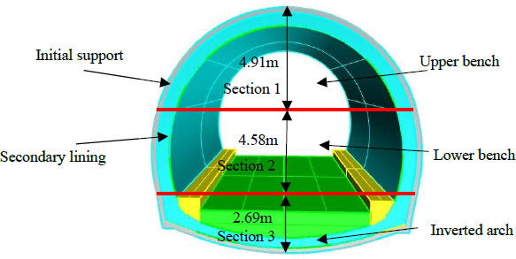
Sanlian Tunnel was designed as a single tunnel with a double track to accommodate the design speed of 160km per hour. It was an extra-long railway tunnel of 12214m (DK300+387~ DK312+ 601). The tunnel was designed with an inverted arch, and the composite lining consisted of the initial support and secondary lining. The tunnel was constructed by the bench cut method, which consisted of four construction steps, as shown in Fig. (1). Step 1: Excavate the upper bench and construct the initial support around Section 1. Step 2: Excavate the lower bench and construct the initial support around Section 2. Step 3: Excavate the inverted arch and construct the filling layer in the Section 3. Step 4: Construct the secondary lining when the initial support deformation stabilized.
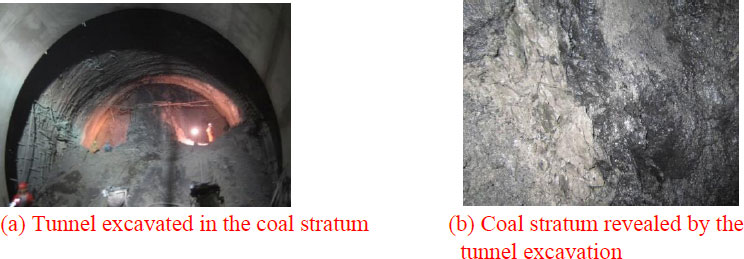
The geology lithological characters of this tunnel consist of mudstone interbedded with sandstone, carbonaceous shale, and coal seams. The mudstone is dark purple and greyish-purple, the sandstone is purplish-red, and the carbonaceous shale is dark gray in color. With a total length of 302 meters, the tunnel between DK306 + 650 and DK306 + 952 traveled through the coal stratum, as shown in Fig. (2a,b). This coal seam belongs to the Upper Permian Xuanwei Group with a burial depth of 130~230 m. The thickness of each coal seam is more than 0.5 m, and the angle of intersection with the tunnel is 20 degrees. The coal is mainly composed of bright coal with block structures in gray-black color. The joints are developed, and the surrounding rocks are broken and soft in the coal stratum.
2.2. Issue of Extensive Deformation
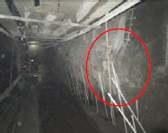
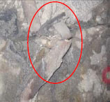
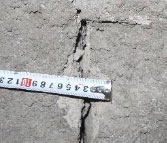
The issue of extensive deformation was encountered during the tunnel construction within the coal stratum between DK306+650 and DK 306+680. After establishing the initial support, the surrounding rocks exhibited an ongoing escalation in deformation, devoid of any indications of stabilization, as shown in Table 1. Notably, the apex experienced an extraordinary settlement of 513mm, while the side walls displayed a striking maximum horizontal convergence of 700mm. This adverse scenario was further compounded by the distortion and fracturing of the steel arch frame, coupled with the fissuring of the sprayed concrete. The problem of the extensive deformations is illustrated in Table 1.
| Description | The Tunnel's Apex Experienced an Extraordinary Settlement of 513mm at DK306+655. |
The Right-side Wall Displayed a Striking Maximum Horizontal Convergence of 700mm at DK306+655. |
The Distortion and Fracturing of the Steel Arch Frame Appeared at DK306+672 on the Right Sidewall. |
The Crack of the Sprayed Concrete in the Initial Support Reached 3cm Wide at DK 306+680. |
|---|---|---|---|---|
| Image | 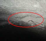 |
 |
 |
 |
2.3. Analysis of Failure Reasons
Examining factors that influence the extensive deformation and failure of the initial support can provide references for proposing the maintenance. Through the field investigation, the failure reasons of the initial support structure can be summarized as follows:
(1) Weak surrounding rocks: The uniaxial compressive strength test was conducted on borehole core samples taken from this tunnel. The average uniaxial compressive strength (i.e., Rc) of the surrounding rock was 1.06MPa, less than 5MPa. According to the Standard for Engineering Classification of Rock Mass (GB/T50218–2014) [22], the surrounding rock of the Sanlian Tunnel was classified as very soft.
(2) High geostress: The in-situ stress test was conducted in this tunnel within the coal stratum. The stress component is presented in Table 2. A positive value represents tensile stress, while a negative value represents compressive stress. The maximum horizontal stress component (i.e., σmax) in the surrounding rocks is 5.90MPa, which is compressive stress: The ratio of Rc (i.e., 1.06MPa) to σmax (i.e., 5.90) is 0.18, less than 4. According to the Standard for Engineering Classification of Rock Mass (GB/T50218–2014) [22], the tunnel was constructed in soft rock masses with high geostress, and extensive deformations may occur in the tunnel. Thus, it can be inferred that high geostress is one factor that influences distress.
(3) Improper design of support structures: The initial support exhibited extensive deformations and fissuring, implying that the design of support structures was not suitable for the coal stratum with high geostress. Thus, the structural design needs to be optimized.
3. EXPERIMENT/METHODS
3.1. Experimental Scheme
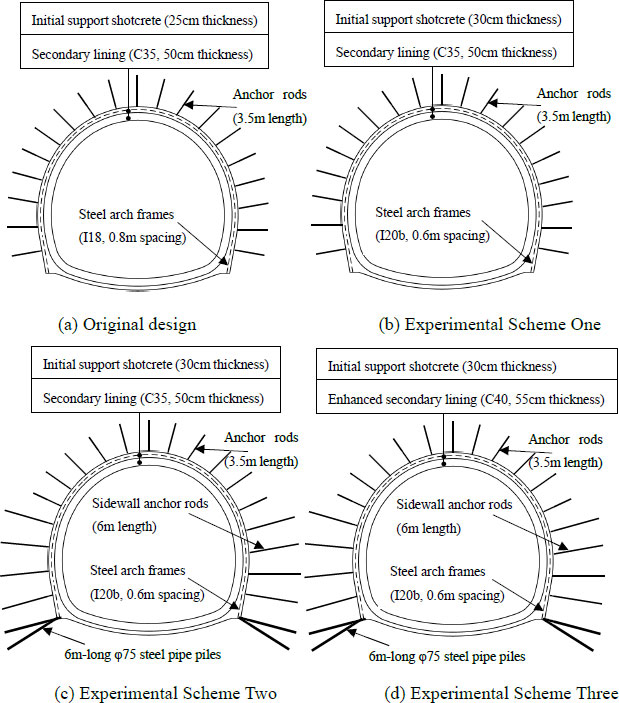
Addressing the issue of extensive deformations calls for innovative control. The goals of this work are to mitigate the deformations and to ensure the tunnel stability. The field experiment was adopted to select the appropriate technical measures to control extensive deformations. Based on the original design of the tunnel, three experiment schemes were developed. Scheme one was applied to the construction of the section between DK306+680 and DK 306+695, Scheme two was applied to the section between DK306+695 and DK 306+710, and Scheme three was applied to the section of DK306+710 and DK 306+725. These three experimental sections had similar geological conditions, namely the coal stratum and high geostress. The displacements and stresses in the tunnel were monitored, and then the appropriate control techniques were selected based on the field observation results. Table 3 and Fig. (3a-d) illustrate the original design and three experimental schemes.
| Stress Component | Value (MPa) | Meaning of Stress Components |
|---|---|---|
| σx | -5.90 |  |
| σy | -4.85 | |
| σz | -4.87 | |
| τxy | -1.10 | |
| τyz | 0.23 | |
| τzx | 0.73 |
| Tunnel Structure | Original Design | Scheme 1 | Scheme 2 | Scheme 3 |
|---|---|---|---|---|
| Steel arch frames | I18, 0.8m spacing | I20b, 0.6m spacing | I20b, 0.6m spacing | I20b, 0.6m spacing |
| Shotcrete | C25, 25cm thickness | C25, 30cm thickness | C25, 30cm thickness | C25, 30cm thickness |
| Anchor rods | 25mm diameter, 3.5m length | 25mm diameter, 3.5m length | (1) 3.5m-long and φ25 anchor rods in the arch (2) 6m-long and φ25 anchor rods at the sidewall |
(1) 3.5m-long and φ25 anchor rods in the arch (2) 6m-long and φ25 anchor rods at the sidewall |
| Steel pipe piles | None | None | 6m-long φ75 steel pipe piles on frame sides | 6m-long φ75 steel pipe piles on frame sides |
| Secondary lining | (1) C35 reinforced concrete with a thickness of 50cm (2) Applied lining when the initial support deformation stabilized |
(1) C35 reinforced concrete with a thickness of 50cm (2) Applied lining when the initial support deformation stabilized |
(1) C35 reinforced concrete with a thickness of 50cm (2) Applied lining when the initial support deformation stabilized |
(1) C40 reinforced concrete with a thickness of 55cm (2) Applied lining if horizontal displacement exceed 450 mm |
| Characteristics of different experimental schemes | - | (1) Enhanced initial support | (1) Enhanced initial support (2) Lengthened sidewall anchor rods and Added steel pipe piles |
(1) Enhanced initial support (2) Lengthened sidewall anchor rods and Added steel pipe piles (3) Timely constructed and enhanced lining |
| Field observation | - | (1) Displacements and stresses of the initial support | (1) Displacements and stresses of the initial support | (1) Displacements and stresses of the initial support (2) Displacements and stresses of the secondary lining |
3.2. Field Observation
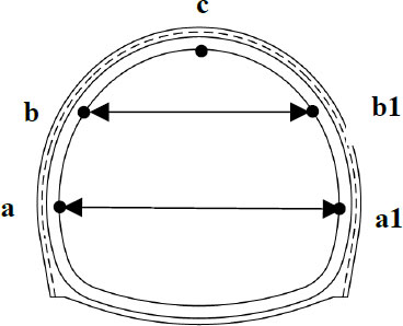
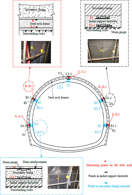
Field observations of displacements and stresses in the tunnel were implemented to evaluate the effectiveness of different experimental schemes. Monitoring points were placed on the tunnel's inner wall surface to monitor the displacement, as illustrated in Fig (4). After excavating the upper bench, measurement point c was arranged at the vault to monitor the apex settlement; moreover, measurement point b and b1 were arranged at the arch hance to monitor the horizontal convergence. After excavating the lower bench, points a and a1 were arranged at the side wall to monitor the horizontal convergence.
Monitoring points were arranged in the initial support and secondary lining to monitor the stress of the tunnel structure, as illustrated in Fig. (5). In order to assess the safety of the steel arch frame in the initial support in different experimental schemes, ten measuring points were arranged to monitor the stress in the steel arch frame, indicated in red color in Fig. (5). Five measuring points (i.e., Points A to E) were arranged at the inner edge of the steel arch frame, while five measuring points (i.e., Points A-1 to E-1) were arranged at the outer edge of the steel arch frame. The outer edge of the steel arch frame is close to the surrounding rocks, while the inner edge of the steel arch frame is adjacent to the secondary lining. Measurement points B, B-1, C, C-1, D, and D-1 were arranged after the excavation of the upper bench, while measurement points A, A-1, E, and E-1 were arranged after the excavation of the lower bench. Surface-mounted concrete strain gauges (JMZX-212) were used to monitor the stress of the steel arch frame. Surface-mounted concrete strain gauges were welded to the inside of the upper and lower flanges of the steel arch frame.
In order to assess the safety of the shotcrete in the initial support, ten measuring points were arranged to monitor the stress in the initial support shotcrete, indicated in black color in Fig (5). Five measuring points (i.e., Points A1 to E1) were arranged at the inner edge of the initial support concrete. In comparison, five measuring points (i.e., Points A1-1 to E1-1) were arranged at the outer edge. The outer edge of the initial support concrete is close to the surrounding rocks. In contrast, the inner edge of the initial support concrete is adjacent to the secondary lining. Embedded concrete strain gauges (JMZX-215) were tied with steel wire to the reinforcement in the initial support structure.
Ten measuring points were arranged to monitor the stress of secondary lining concrete, indicated in blue color in Fig. (5). Points A2 ~ E2 were arranged at the inner edge of the secondary lining concrete, while points A2-1 ~ E2-1 were arranged at the outer edge. The inner edge of the secondary lining is adjacent to the tunnel clearance, while the outer edge is close to the initial support concrete. Embedded concrete strain gauges (JMZX-215) were used to monitor the stress of secondary lining concrete.
4. RESULTS
4.1. Results of Scheme One
4.1.1. Displacement of Initial Support
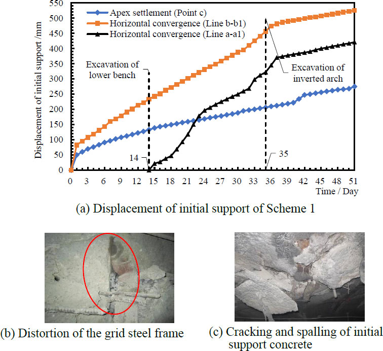
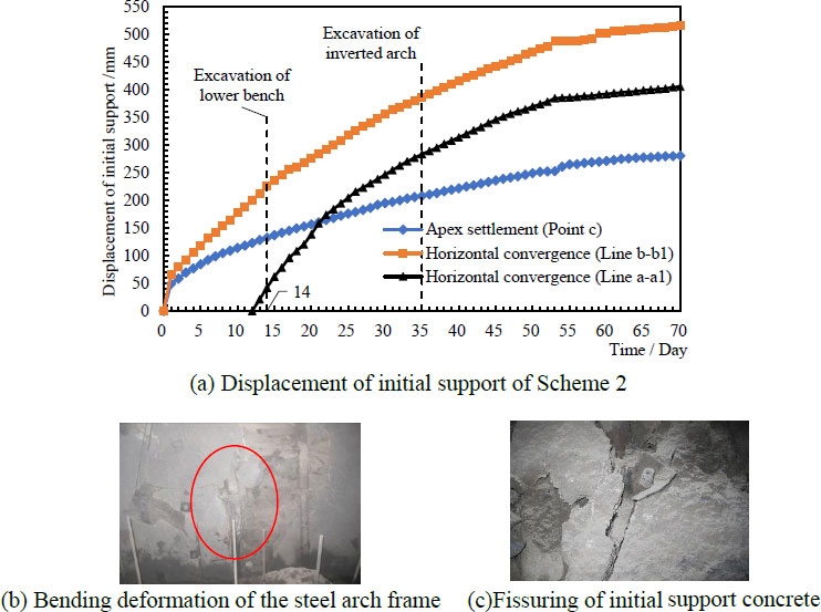
The monitoring results of the initial support displacement in Scheme One are shown in Fig. (6a). At the beginning of the monitoring period, the displacement of the initial support increased quickly. It indicates rapid settlement at the vault and a speedy horizontal displacement of the hance into the tunnel's interior after the upper bench was constructed. After excavating the lower bench (i.e., on the fourteenth day), the same rapidly increasing trend was shown at the horizontal convergence of Line a-a1 on the side wall. The initial support was disturbed by the excavation of the inverted arch (i.e., on the thirty-fifth day), and the displacement showed fluctuations and continued to increase. On the fifty-first day, the apex settlement at Point C reached 275mm, and the maximum horizontal convergence at Line b-b1 reached 524.9mm. As seen in Fig. (6b), the distortion of the grid steel frame appeared in Experimental Scheme One. Furthermore, cracking and spalling were examined at the vault of initial support concrete, as shown in Fig. (6c). Moreover, the initial support intruded into the tunnel clearance limit. These indicate that the structural design in Scheme One cannot effectively control the large deformation of the surrounding rock.
4.1.2. Stress of Initial Support
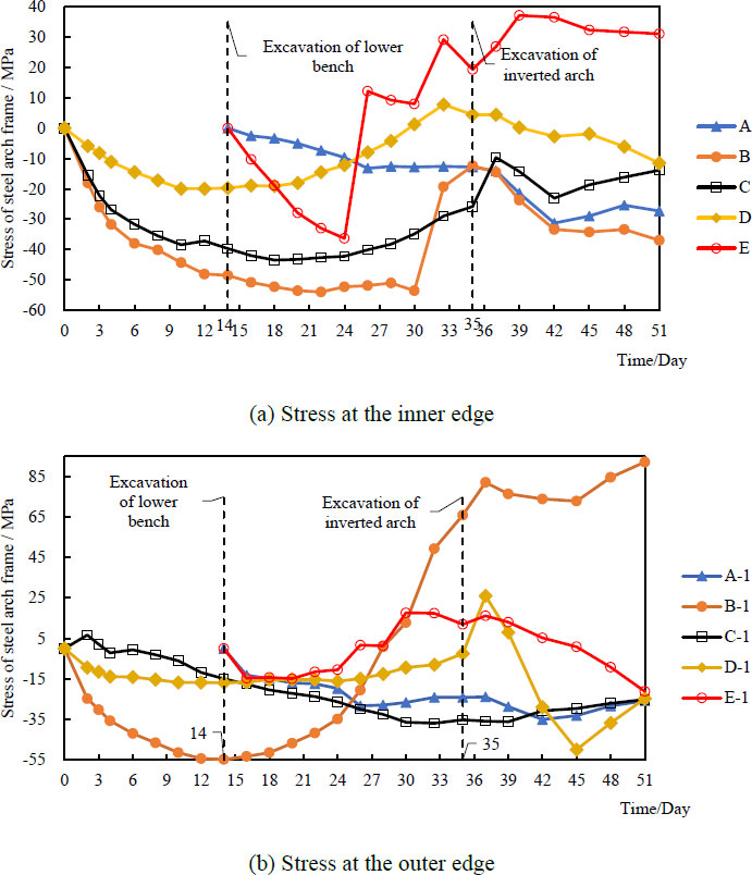
The monitoring results of stress at the inner and outer edge of the steel arch frame in Scheme One are presented in Fig. (7a,b). The positive stress indicates tensile stress, while the negative stress indicates compressive stress. As soon as the upper bench was excavated, the steel arch frame started to support loads, and the stress quickly increased. After excavating the lower bench, the stresses at the side wall (i.e., at Points A, E, A-1, and E-1) increased rapidly as the steel arch frames at the sidewall were immediately subjected to loads after installation. Then, the stresses in the steel arch frame experienced significant changes due to the excavation of the inverted arch on the thirty-fifth day. When the initial support deformation intruded into the tunnel clearance limit, i.e., on the fifty-first day, the maximum tensile stress in the steel arch was 92.17 MPa, which occurred at point B-1, and the maximum compressive stress was -36.96 MPa, which occurred at point B. Throughout the monitoring period, the stresses of the steel arch were generally in substantial fluctuation and did not reach a steady state. This implies that Scheme One cannot effectively solve the problem of extensive deformations.
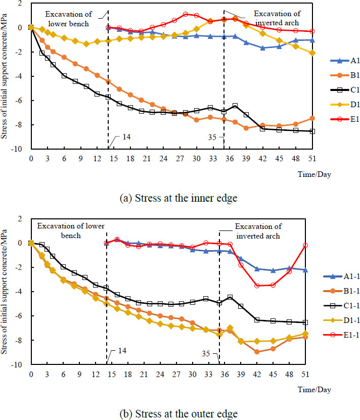
The monitoring results of stress at the inner and outer edge of the initial support concrete in experimental scheme One are illustrated in Fig. (8a,b). The positive stress indicates tensile stress, while the negative stress indicates compressive stress. The initial support concrete stress had a rapid increase trend at the start of the monitoring period. After the fourteenth day, i.e., when the lower step was excavated, the shotcrete at the sidewalls started to take the load, and the stress gradually increased. Later, the initial supporting concrete stresses showed fluctuations, and continued to increase after the excavation of the inverted arch on the thirty-fifth day. At the end of the monitoring period, when the initial support intruded into the tunnel clearance limit, all measuring points showed compressive stress, with a maximum compressive stress of -8.53MPa (i.e., Point C1) at the inner edge of the vault. Throughout the monitoring period, the stress of initial support concrete continued to increase without stabilizing. This implies that the stresses continued to be adjusted without reaching equilibrium, and Scheme One could not effectively solve the large deformation problem encountered in this tunnel.
4.2. Results of Scheme Two
4.2.1. Displacement of Initial Support
The displacements of the initial support in Scheme Two showed the same trend as Scheme One, i.e., a continuous increase, as shown in Fig. (9a-c). On the seventieth day, the apex settlement at Point C reached 280.1mm, and the maximum horizontal convergence at Line b-b1 reached 515.4mm. The initial support structure of Scheme Two still intruded into the tunnel clearance limit. The difference is that the intrusion of the initial support into the tunnel clearance limit in Scheme Two was on the seventieth day, which was nineteen days later than that in Scheme One. Fig. (6b and c) show the on-site image of the initial support structure in Scheme Two. The bending deformation of steel arch frames and fissuring of initial support concrete were examined in this experimental scheme. The failure phenomenon implies that the initial support of Scheme Two still cannot effectively solve the problem of extensive deformations.
4.2.2. Stress of Initial Support
The stresses of initial support in Scheme Two continued to increase and did not reach a steady state. At the end of the observation period, when the initial support intruded into the tunnel clearance limit, the maximum tensile and compressive stresses in the steel arch frame were 122.23 MPa and -98.75 MPa, respectively. Meanwhile, the maximum tensile and compressive stresses in the initial support concrete were 2.42 MPa and -18.91 MPa, respectively.
4.3. Results of Scheme Three
4.3.1. Displacement of Initial Support
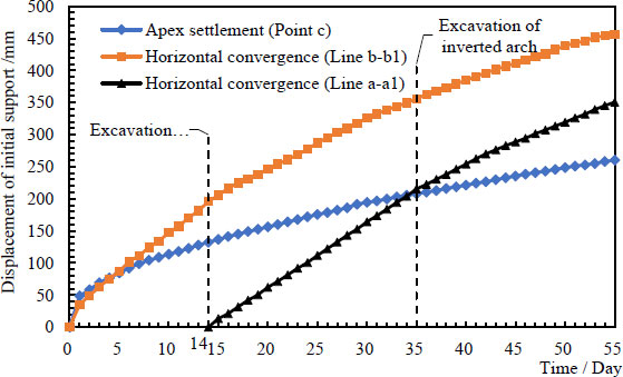
The monitoring results of the initial support displacement of Scheme Three are shown in Fig. (10). During the first fourteen days of the monitoring period, the displacement of the initial support (i.e., Line b-b1, Point c) increased quickly. It indicates there was a rapid displacement of the surrounding rock towards the interior of the tunnel after the upper bench was excavated. After the excavation of the lower bench (i.e., on the fourteenth day), the horizontal convergence at Line a-a1 on the side wall showed rapid growth. Then, the initial support was disturbed by excavating the inverted arch (i.e., on the thirty-fifth day), and the displacement continued to increase. On the fifty-fifth day after the tunnel excavation, the vault settlement of the initial support at point c was 260.3mm. Additionally, the cumulative horizontal convergence at Line a-a1 on the side wall and Line b-b1 on the hance was 350.7mm and 456.5mm, respectively. In Scheme Three, when the horizontal convergence of the initial tunnel support exceeded 450 mm, the secondary lining was constructed. Hence, the monitoring of the initial support displacement ended, and the secondary lining was constructed on the fifty-fifth day.
4.3.2. Displacement of Secondary Lining
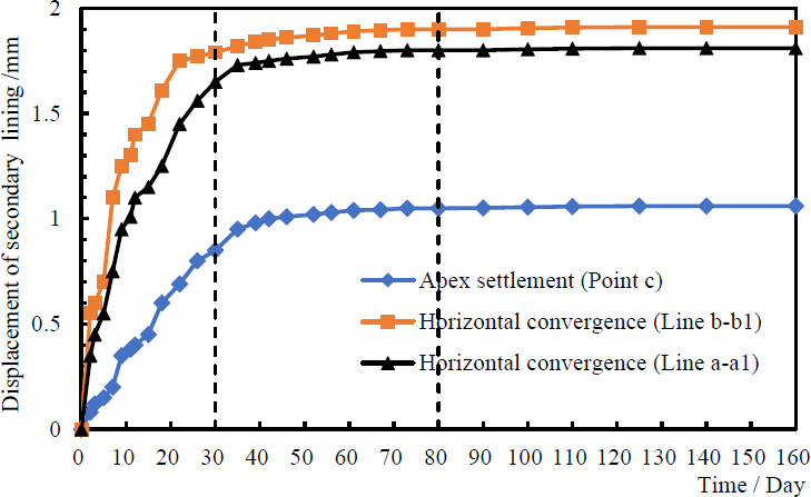
Fig. (11) depicts the monitoring results of the secondary lining displacement. During the first thirty days of the monitoring period, the displacement of the secondary lining increased quickly. It implies that the secondary lining that had just been constructed worked together with the initial support to resist the surrounding rock's large deformation toward the tunnel's interior. A continuous but slow growth appeared in the displacement from the thirtieth to the eightieth day. This may be because the combined effect of the secondary lining and initial support gradually stabilized the surrounding rock displacement. Then, the displacement of the secondary lining remained almost steady after the eightieth day. At the end of the monitoring period, the vault settlement at point c was 1.06mm. Additionally, the cumulative horizontal convergence at Line a-a1 on the side wall and at Line b-b1 on the hance was 1.81mm and 1.91mm, respectively. Overall, eighty days after completion of the secondary lining, the secondary lining displacement reached a steady state; moreover, the cumulative displacement of the secondary lining was not significant. It can be inferred that the timely constructed and enhanced lining structure could effectively manage the condition of the extensive deformation.
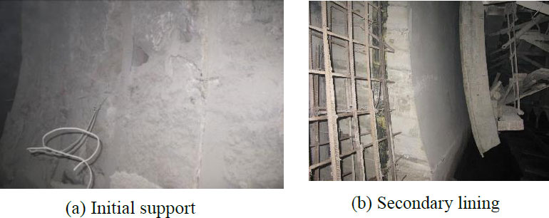
Fig. (12a,b) shows the images of the initial support and secondary lining in Scheme Three. No significant deformations were monitored in the initial support prior to the construction of the secondary lining. Moreover, there were no cracks on the surface of the secondary lining during the monitoring period. From the on-site situation of tunnel construction, it is inferred that Scheme Three is effective in controlling the extensive deformation.
4.3.3. Stress of Initial Support
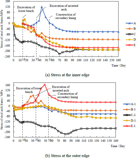
The monitoring results of stress in the steel arch frame are presented in Fig. (13a,b). The positive stress indicates tensile stress, while the negative stress indicates compressive stress. The steel arch frame began to bear loads immediately after completing the upper bench, and the compressive stress in the steel arch frame increased rapidly. On the fourteenth day, i.e., when the lower step was excavated, the compressive stresses at the inner and outer edge of the vault reached -133.77MPa (i.e., at Point C) and -126.21MPa (i.e., at Point C-1), respectively. After excavating the lower bench, the stresses at the side wall (i.e., at Points A, E, A-1, and E-1) increased rapidly as the steel arch frames at the sidewall had just been erected and were immediately subjected to loads. Influenced by the excavation of the inverted arch on the thirty-fifth day, there were large fluctuations in the stresses at the monitoring points of the steel arch frame. The maximum tensile stresses of 120.12MPa (i.e., Point A at the left side wall) and 164.64MPa (i.e., Point E-1 at the right side wall) appeared at the inner and outer edge of the steel arch frame, respectively. Later, after the construction of the secondary lining on the fifty-fifth day, the tensile stresses in the steel arch frame gradually decreased, while the compressive stress gradually increased. Afterward, the stress of the steel arch frame was gradually adjusted and tended to be steady in the initial support, as the reinforced secondary lining and the initial support acted jointly to bear loads. After the one hundred and thirty-fifth day, the stresses changed very little and eventually reached a steady state. At the end of the monitoring period, the maximum compressive stresses occurred at the vault, i.e., -191.5 MPa (Point C) at the inner edge and -172.2 MPa (Point C-1) at the outer edge of the steel arch frame.
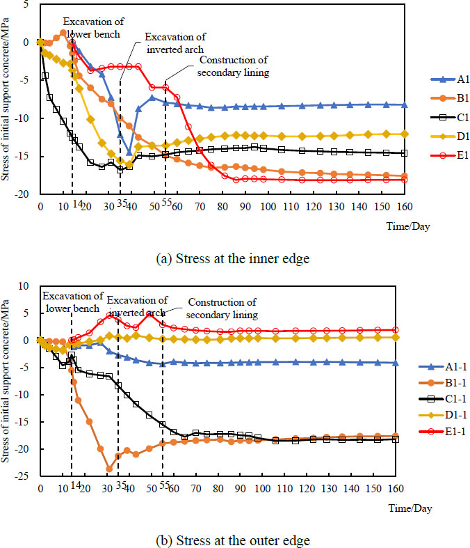
The monitoring results of the initial support concrete stress are illustrated in Fig. (14a,b), separately. In the beginning, the stress showed a rapid growth trend. It suggests that the initial support concrete resisted the deformation of the surrounding rocks and bore considerable compressive stress. On the fourteenth day, i.e., when the lower step was excavated, the stress in the initial support concrete increased rapidly, with a maximum tensile stress of -23.73MPa at Point B1-1. This implies that the surrounding rocks underwent a large extrusion deformation towards the tunnel's interior, resulting in large loads on the initial support. Influenced by the excavation of the inverted arch on the thirty-fifth day, there were large fluctuations in the stresses. Later, after the construction of the secondary lining on the fifty-fifth day, the stress was gradually adjusted and tended to be steady, as the reinforced secondary lining and the initial support acted jointly to bear loads. After the one hundred and twentieth day, the stresses changed very little and remained almost steady. At the end of the monitoring period, two monitoring points (i.e., D-1 and E-1) presented tensile stress, while the other monitoring points showed compressive stresses. The maximum tensile stress of 1.89MPa (i.e., Point E1-1 at the right-side wall) appeared at the outer edge. Meanwhile, the maximum compressive stress of -18.22MPa (i.e., Point C1-1 at the vault) occurred at the outer edge of the initial support concrete.
4.3.4. Stress of Secondary lining
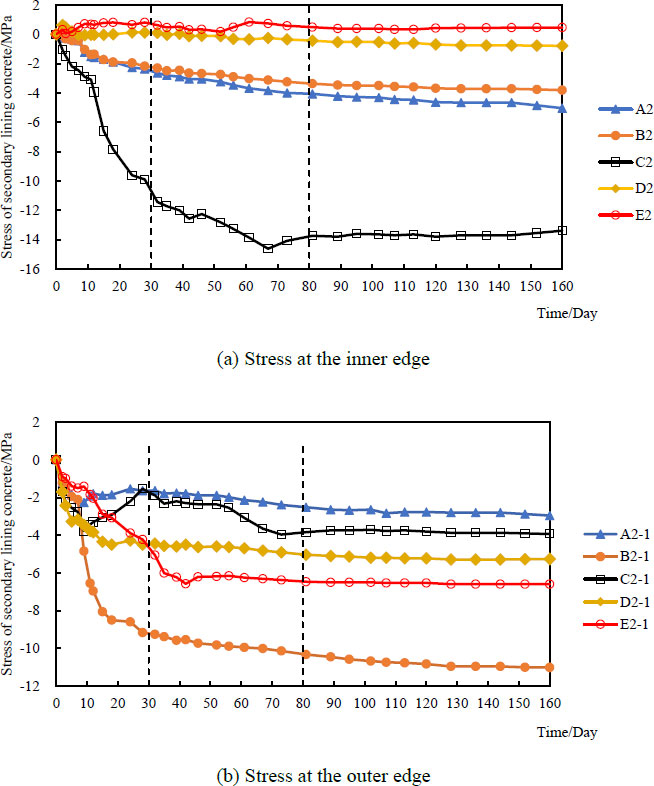
Fig. (15a,b) depicts the monitoring results of the secondary lining concrete stress. In the first thirty days of the monitoring period, the stress in the secondary lining concrete increased quickly, implying that the concrete lining began to bear loads after the lining was completed. A continuous but slow growth appeared in the lining stress from the thirtieth to the eightieth day. This is probably because the enhanced secondary lining was gradually controlling the extensive deformation of the surrounding rock. During this period, a maximum compressive stress of -14.63MPa (i.e., point C2) showed at the inner edge of the vault. The secondary lining bears loads together with the initial support, so the stress of the secondary lining was gradually adjusted and tended to be steady after the eightieth day. The stress at point C2 slightly reduced, while the stress at point B2-1 increased somewhat. At the end of the monitoring period, the ultimate compressive stress was -13.4 MPa (i.e., Point C2), and the ultimate tensile stress was 0.46 MPa (i.e., Point E2).
5. DISCUSSION
5.1. Comparison of Experiment Results
The comparison of the experimental results is illustrated in Table 4. The initial support for both Scheme One and Two intruded into the tunnel clearance limit, indicating that the enhanced initial support was ineffective in controlling the extensive deformation of surrounding rocks. The intrusion of the initial support into the clearance limit was delayed in Scheme Two compared to that in Scheme One. This indicates that the combined use of the enhanced initial support, lengthened sidewall anchor rods and added steel pipe piles can slow down the rate of surrounding rock displacement and buy time for the construction of the secondary lining. In Scheme Three, the enhanced secondary lining was constructed before the initial support intruded into the clearance limit, i.e., when the horizontal displacement exceeded 450 mm. The secondary lining bears loads together with the initial support, which can effectively control the extensive deformation.
| Experimental Scheme | Scheme 1 | Scheme 2 | Scheme 3 | Comparison Diagram |
|---|---|---|---|---|
| Characteristics of Initial Support Displacement | The displacement continued to increase with no sign of stabilization. | The displacement continued to increase with no sign of stabilization. | Prior to the construction of the secondary lining, the displacement of the initial support continued to increase. |  |
| The time of intrusion of initial support into the tunnel clearance limits | On the fifty-first day | On the seventieth day | The secondary lining was constructed on the fifty-fifth day, and the initial support did not intrude into the clearance limits. | |
| Characteristics of initial support stress | The initial support stresses showed large fluctuations and continued to increase. | The stresses in the initial support continued to increase and did not reach a stable state. | The initial support stress went through a process of rapid increase, fluctuation, and stabilization; it eventually reached a steady state after the 65th to 80th day of the secondary lining construction. | 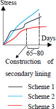 |
| Characteristics of secondary lining displacement | The secondary lining was not constructed due to the initial support intruding into the clearance limits. | This displacement went through three stages of: rapid increase, slow increase and stabilization. Eighty days after the completion of the secondary lining, the displacement reached a steady state. |  |
|
| Characteristics of secondary lining stress | The secondary lining stresses first increased in fluctuation and then gradually stabilized after the 80th day of the completion of the secondary lining. | 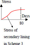 |
||
| Tunnel Structure | Maximum Stress in Scheme 1 | Maximum Stress in Scheme 2 | Maximum Stress in Scheme 3 | Allowable Stress |
|---|---|---|---|---|
| Steel arch frame | +92.17MPa, -36.96 MPa |
+122.23 MPa, -98.75 MPa |
+28.35 MPa, -191.5 |
+210 MPa (HPB300), -210 MPa (HPB300) |
| Initial support concrete | No tensile stress, -8.53 MPa |
+2.42 MPa, -18.91 MPa |
+1.89 MPa, -18.22 MPa |
+2 MPa (C25), -18.5 MPa (C25) |
| Secondary lining concrete | The secondary lining was not constructed | +0.46 MPa, -13.4 MPa |
+2.7 MPa (C40), -36.9 MPa (C40) |
|
| Item | Left Side Wall(A) | Left Hance(B) | Vault(C) | Right Hance(D) | Right Side Wall(E) | Schematic |
|---|---|---|---|---|---|---|
| Stress (inner edge)\MPa | -5.04 | -3.81 | -13.40 | -0.79 | 0.46 |  |
| Stress (outer edge) \MPa | -2.96 | -11.02 | -3.94 | -5.26 | -6.60 | |
| Axial force \kN | -2200.3 | -4078.7 | -4766.9 | -1663.2 | -1688.4 | |
| Bending moment \ kN·m | 52.4 | -181.7 | 238.4 | -112.8 | -177.9 | |
| Safety factor | 9.23 | 4.60 | 3.86 | 10.38 | 9.06 |
At the end of the monitoring period, the maximum stresses of the tunnel structure in the three experimental schemes are illustrated in Table 5. The strength limits are obtained from the Code for Design of Railway Tunnel (TB 10003 - 2016) [15]. In Scheme One, the stresses of the initial support structure did not exceed the allowable stresses, which may be due to excessive deformation of the initial support without providing sufficient resistance to the surrounding rock deformation. In Scheme Two, the support structure delayed the intrusion of the initial support into the clearance limit, and the stresses slightly exceeded the allowable stresses, implying that the support structure provided stronger resistance to the deformation of surrounding rocks. The support structure of Scheme Three was effective in resisting the surrounding rock deformation, and the stresses in the steel arch frame and initial support concrete were relatively high. However, the stress of initial support did not exceed the allowable stresses, which may be because the initial support bore the loads together with the secondary lining. The stress of the secondary lining of scheme Three did not exceed the allowable stress, indicating that the proposed enhanced secondary lining structure was in a safe state.
5.2. Safety Factor of Secondary Lining in Scheme Three
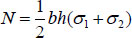
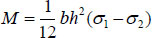
Regarding Scheme Three, the inner forces and safety factor of the secondary lining can be calculated based on the monitored stresses at the end of the monitoring period. Firstly, the axial force N and bending moment M of the secondary lining are calculated according to formulas (1) and (2) [16]. Positive axial forces represent tension, while negative axial forces represent pressure. Positive bending moments represent tension on the outside of the lining, while negative bending moments represent tension on the inside. The outside is close to the surrounding rocks, while the inside is adjacent to the tunnel clearance (Eqs 1, 2).
 |
(1) |
 |
(2) |
where b is the width of the calculated cross-section, i.e., 1 m along the longitudinal axis of the tunnel, h is the thickness of the secondary lining, i.e., 0.55m. σ1 is the stress acting at the outer edge of the lining, and σ2 is the stress acting at the inner edge.
Based on the inner force values, the safety factors of the secondary lining are calculated according to the calculation principle of the section strength check for eccentrically compressed reinforced concrete members with rectangular sections, as illustrated in Code for Design of Railway Tunnel (TB 10003 - 2016) [15]. The safety factor of the secondary lining is the ratio of the bearing capacity to the inner force. The results of safety factors are presented in Table 6.
As seen in Table 6, negative axial forces, namely pressure, were applied in the lining structure. The maximum axial force value was 4766.9kN and was located at section C in the vault, while the minimum axial force value was 1663.2kN and was located at section D at the right hance. Positive bending moments were applied in Sections A and C in the secondary lining, indicating tension on the outside of the lining. Additionally, a negative bending moment was applied in Sections B, D and E, indicating tension on the inside of the lining. The maximum bending moment value was 238.4kN·m and was located at section C in the vault, while the minimum bending moment value was 52.4kN·m and was located at section A on the left side wall.
The maximum safety factor was 10.38, located in section D at the right hance. The minimum safety factor was 3.86, located in section C at the vault. As illustrated in the Code for Design of Railway Tunnel (TB 10003 - 2016) [15], the safety factor of lining must be greater than 2.4. As seen in Table 6, safety factors meet this requirement. Therefore, the secondary lining structure in Scheme Three was safe, and the timely constructed and enhanced lining structure for managing extensive deformations in the coal stratum may achieve a good effect.
5.3. Control Technology for Managing Extensive Deformations
This work proposed a “timely constructed and enhanced lining structure” scheme encompassing five innovative control technologies to manage extensive deformations. Firstly, the steel arch frames were strengthened from I18 to I20b, and their spacing was reduced from 0.8m to 0.6m. Secondly, the length of anchor rods at the sidewall was increased from 3.5m to 6m, which was used to control the horizontal convergent deformation. Thirdly, two 6m-long φ75 steel pipe piles are installed on each side of each steel arch frame to control the downward settlement. Fourthly, the secondary lining was strengthened by increasing the thickness from 50cm to 55cm and the reinforced concrete from C35 to C40. Fifthly, the secondary lining was constructed when the horizontal displacement of the initial support exceeded 450 mm. In short, the secondary lining and the initial support acted jointly to control the extensive deformation.
The contribution of this study consists of three aspects. Firstly, this work concentrates on exploring the control measures of extensive deformations in tunnels excavated in the coal stratum, which is widely distributed in Southwest China. Secondly, compared to most existing studies that use numerical simulation or indoor experiment methods, field monitoring results can truly reflect the force characteristics of the tunnel structure. The control technology was proposed utilizing the field experiment method, which represents an enhancement in this study. Thirdly, the field observation results affirmed the secure condition of the tunnel structure in this work. Consequently, the proposed “timely constructed and enhanced lining structure” control technology can be applied to manage extensive deformations of tunnels in coal stratum. The suggested control technology holds substantial promise for practical implementation in engineering scenarios.
CONCLUSION
In this study, three types of support structures were constructed to explore effective control measures for extensive deformations of tunnels in coal stratum and field monitoring was implemented to evaluate the effectiveness of different experimental schemes. The main conclusions are as follows:
(1) Strengthening the initial support structure alone cannot control extensive deformations of surrounding rocks. Combined use of enhanced initial support, lengthened sidewall anchor rods, and added steel pipe piles can slow down the rate of the surrounding rock deformation but cannot also effectively control the large deformation.
(2) Based on the above measures, applying enhanced and timely construction of secondary lining, the secondary lining and initial support synergistically control the extensive deformation, achieving good effects. The field observation results show that the lining structure is in a safe condition.
(3) The “timely constructed and enhanced lining structure” technology is proposed to control the extensive deformation of tunnels in the coal stratum. The steel arch frames are reinforced, and their spacing is narrowed. The sidewall anchor rods are lengthened for the control of horizontal deformation, and the steel pipe piles are added to manage the downward settlement. Furthermore, the secondary lining is enhanced, and the lining is applied if the horizontal displacement of the initial support exceeds 450 mm. The proposed control technology can provide a reference for tunnels excavated in the coal stratum.
CONSENT FOR PUBLICATION
Not applicable.
FUNDING
This work was supported by the Science and Technology Research Project of Henan Province (grant number 162102310403) and the Research Project of Henan University of Engineering (grant number 2021JYYB039).
CONFLICT OF INTEREST
The authors declare no conflict of interest, financial or otherwise.
ACKNOWLEDGEMENTS
Declared none.

