All published articles of this journal are available on ScienceDirect.

Seismic Response Analysis of Rectangular Reinforced Concrete Tank Constructed on Loess Soil
Abstract
Introduction
Liquid storage tanks are an essential container structure widely used in various industries. In earthquake disasters, liquid storage tanks cause not only direct disasters but also induce secondary severe disasters, such as fires, explosions, nuclear leaks, and human and animal poisoning. The latest research on seismic analysis of structures showed that soils with different stiffness can affect the seismic response characteristics of surface structures, and various irregular topographies can also alter the degree of seismic-induced damage to surface structures. Studying the seismic response of liquid storage tanks can mitigate the risk of earthquake damage to these vital structures.
Methods
This study used finite element simulations. Three sizes of liquid storage tanks with different aspect ratios were selected, including the squat, square, and slender tanks. Three conditions were considered for the tanks' liquid: empty, half-filled, and fully filled. Two types of topographies were considered, including flat and step-like slope topography with an inclination angle of 116.6°. Nine natural earthquake records were used for seismic analysis and divided into three categories: high-frequency, medium-frequency, and low-frequency. Established finite element models were validated through comparison with the results of other studies. The dynamic time history analysis was carried out for each finite element model. The tank's base shear forces, the normal stress in the tank wall, the shear stress in the tank bottom, and the maximum displacement of the tank wall were measured and compared.
Results
The step-like slope topography and loess soil significantly amplified the seismic response of the liquid storage tank. Moreover, as the liquid height and the tanks’ aspect ratio increased, the seismic damage intensity also increased. The seismic response of the liquid storage tank was generally more sensitive to low-frequency and medium-frequency seismic records. The Eurocode 8’s equation underestimated tanks’ base shear when located on a step-like slope topography.
Conclusion
The obtained results demonstrated the significant effect of irregular topography and loess soil on the seismic response of liquid storage tanks. Therefore, it was concluded that they should be considered when liquid storage tanks are designed for seismic actions.
1. INTRODUCTION
A liquid storage tank is an essential container structure for storing liquid medium and is widely used in the petrochemical industry, military construction, nuclear energy, civil and hydraulic engineering, urban water resources and other fields. Due to the differences in application scenarios and physical and chemical properties of stored liquids, the volume of liquid storage tanks varies from a few cubic meters to several thousand cubic meters, with geometrical shapes generally cylindrical, rectangular, spherical, and conical. Moreover, the materials used for manufacturing are usually concrete, metal, rubber and inorganic fibers [1]. Earthquakes are natural disasters that can cause fatal damage to all kinds of surface structures, including liquid storage tanks. Compared with natural ageing, design defects, and manufacturing errors, the damage caused by earthquakes to liquid storage tanks is almost devastating and irreparable [2].
Moreover, under the excitation of severe earthquakes, storage tanks may induce serious secondary disasters simultaneously as direct disasters [3]. On June 16, 1964, an earthquake of magnitude 7.5 occurred in Niigata, Japan; after the destruction of the metal cylindrical oil storage tanks in the epicenter area, an explosion occurred and triggered a fire that lasted 15 days and burned 84 oil storage tanks, causing unpredictable economic losses and air pollution to the local area [4]. On July 28, 1976, a 7.8 magnitude earthquake struck Tangshan, China, destroying most residents' concrete cylindrical or rectangular water storage tanks used for drinking water, seriously hindering post-disaster rescue [5]. On March 11, 2011, a 9.0 magnitude earthquake occurred in the Pacific Ocean in northeastern Japan; the damage to the storage tank of nuclear materials at Fukushima Nuclear Power Station led to nuclear leakage, which still seriously affects the global ecological environment [6]. There are many other examples of liquid storage tanks damaged by earthquakes, causing severe secondary disasters, such as the United States' Northridge earthquake in 1994, China's Wenchuan earthquake in 2008, and the Central Sulawesi earthquake in Indonesia in 2018. The damage to storage tanks during seismic events has caused incalculable economic losses, environmental threats, and casualties worldwide. Therefore, how to effectively avoid and reduce earthquake damage to liquid storage tanks has been continuously and widely discussed.
Compared with other structures, the dynamic response of a storage tank under seismic actions is relatively more complex due to its liquid-structure and soil-structure interactions [7]. When the base of a liquid storage tank is subject to ground vibrations, the contained sloshing liquid imposes hydrodynamic pressure on the tank's walls, which has an intensity and distribution different from hydrostatic pressure [8]. The magnitude and distribution of these pressures depend on the features of earthquake records, the characteristics of liquid, and the geometry and physical properties of the tank itself [9]. Housner [10] first established a simplified mechanical model of the liquid storage tank based on the mass-spring system, assuming that the tank wall is entirely rigid, which was widely recognized. However, the simplified mechanical tank model based on rigid walls was proved to underestimate the extent of damage caused by ground motion seriously. Veletsos [11] proposed a simplified mechanical model for liquid storage tanks based on a single-degree-of-freedom model, assuming a flexible wall and a rigid basis.
Although the theory of rigid tank walls or flexible tank walls can better explain the storage tank’s fluid-structure coupling interaction in underground motion, it ignores the soil’s influence on the ground motion response features of surface structures [9]. Because soil parameters, such as stiffness and damping can affect the seismic wave's propagation characteristics, Güler et al. optimized the mechanical model of storage tanks based on fluid-structure-soil coupling interaction [12]. Lee et al. conducted seismic analysis on cylindrical liquid storage tanks considering the coupling interaction between soil and structures. The research results showed that flexible soil can exacerbate the tank's seismic response and increase the dynamic water pressure inside the tank [13]. Liu et al. used the finite element method to study the seismic response of the storage tanks. Results showed that as the soil stiffness decreased, the displacement of the storage tank increased, decreasing the natural frequency [14]. Wu et al. studied liquid storage tanks' low vibration response characteristics under vertical seismic excitation. They pointed out that vertical excitation amplified the convection and pulse motion of the fluid inside the tank. Moreover, under near-fault seismic excitation, the height of the sloshing liquid increased by 142% [15].
Guided by simplified mechanical models, some countries have formulated seismic design and construction standards for various storage tank types and continuously revised them to account for new findings. The seismic design codes with particular influence in the world include GB50341 [16] in China, API650 [17] in the United States, JIS-B8501 [18] in Japan, and DIN4119-1 [19] in Germany. The primary function of these codes is to avoid the axial instability of the liquid storage tank and the overflow of liquid in the tank under the action of earthquakes [20]. Besides, these codes provide simplified equations to estimate tanks’ sloshing natural frequency, base shear, and maximum sloshing wave height. Due to employed simplifications, these equations lose their accuracy under complex conditions like the constructed tanks on sloped grounds or very soft soils. Therefore, detailed simulations must be taken into account for such conditions.
Under the rapid development of the global economy and industry, the number and types of liquid storage tanks are also increasing and appearing in all corners of the world; at the same time, the construction site conditions of liquid storage tanks are becoming more complex and diverse [21]. The geological and geomorphic features on the earth are widely distributed, and humans usually choose an environmentally livable area far away from natural disasters to ensure economic development and safety [22]. Therefore, plenty of liquid storage tanks for different purposes have been built or will be built in relatively harsh environments with irregular topographies and thick loess layers. During earthquakes, irregular topographies can amplify the peak ground acceleration and prolong its duration. This amplification can increase seismic-induced damage to reinforced concrete liquid storage tanks [23].
Moreover, many studies have shown that the loess layer can experience seismic liquefaction and uneven settlement under the action of massive earthquakes, which can lead to the instability of the foundation [21]. As the thickness of the loess layer increases, the peak acceleration of earthquakes on the surface increases. Besides, the response spectrum becomes more significant for longer periods [24]. The irregular topographies and loess soil layer significantly aggravate the earthquake damage to the surface structures. Therefore, this study investigates the effects of irregular topographies and loess soil layers on the seismic response of reinforced concrete storage tanks.
2. MATERIALS AND METHODS
2.1. Size of Liquid Storage Tanks
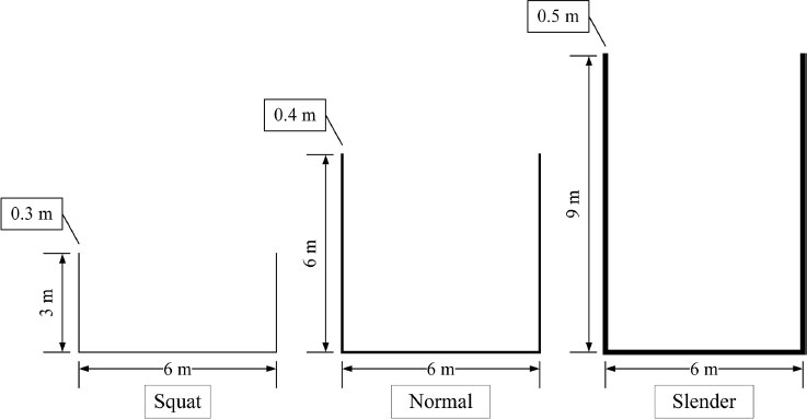
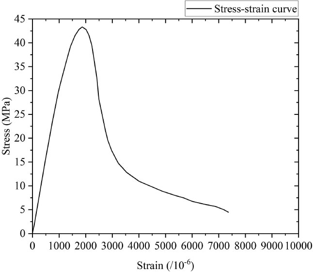
In this study, the internal diameter of rectangular concrete liquid storage tanks was 6 m, similar to previous studies [25]. Besides, following a previous study [26], three different aspect ratios were selected for the tanks. These three aspect ratios equaled 0.5, 1, and 1.5, representing a squat, a square, and a slender tank, respectively. The thickness of the tank wall and its foundation was selected based on the previous study [15] and equaled 0.3 m, 0.4 m, and 0.5 m for tanks with aspect ratios of 0.5, 1, and 1.5, respectively. The construction material of the liquid storage tank was concrete, and the material property of concrete followed the suggested values by Asgari et al. [27]. The density of employed concrete was 2500 kg/m3, Young's modulus was 32 GPa, and Poisson's ratio was 0.2. The selected dimensions for different types of liquid storage tanks in this study are shown in Table 1. The material properties of concrete are shown in Table 2. The two-dimensional schematic diagram of the liquid storage tanks is shown in Fig. (1). The stress-strain curve of the concrete is shown in Fig. (2).
2.2. Conditions of Liquid Storage Tanks
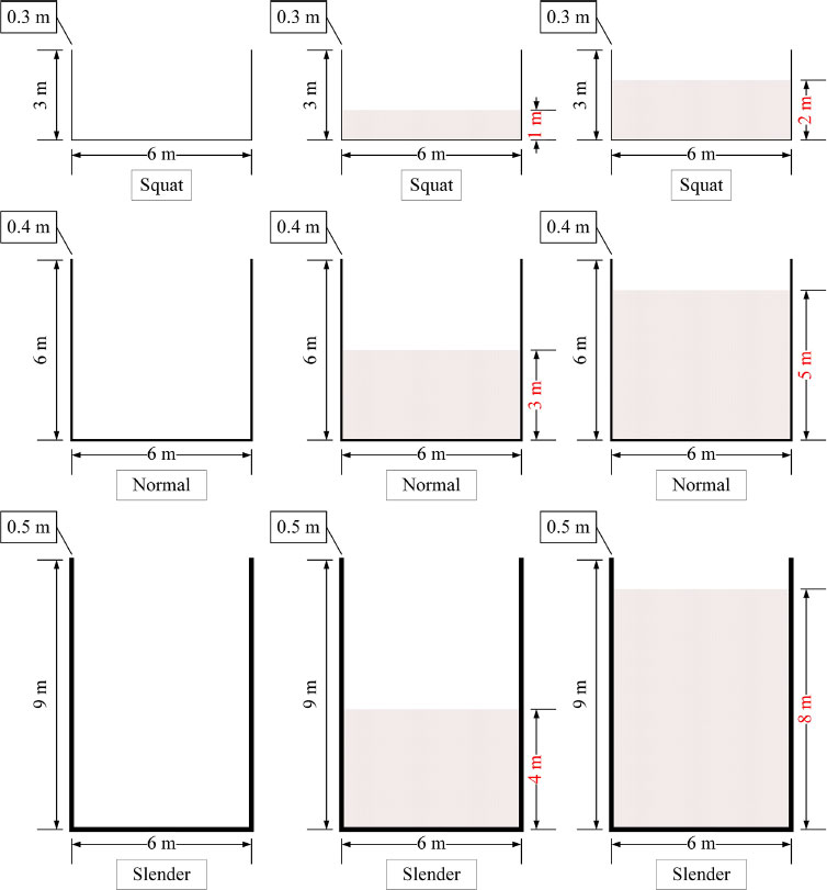
The liquid in the storage tank was water, with a 1000 kg/m3. The volumetric weight of water is 9800 N/m3, the viscosity coefficient of water movement is 0.01559 cm2/s, the bulk elastic modulus of water is 21.9 MPa, the Poisson's ratio of water is usually defined as 0.5, which means that water cannot be compressed. It should be noted that three different liquid heights were considered in this study, including empty, half-filled, and fully-filled. In the squat tank, the liquid heights were 0 m, 1 m and 2 m; in the square tank, the liquid heights were 0 m, 3 m and 5 m; in the slender tank, the liquid heights were 0 m, 4 m and 8 m. The liquid storage tanks considered in this study are shown in Table 3. The two-dimensional schematic diagram of the liquid heights of different types of liquid storage tanks is displayed in Fig. (3).
| Type/Dimension | Width (m) | Height (m) | Thickness (m) | Aspect ratio |
|---|---|---|---|---|
| Squat | 6 | 3 | 0.3 | 0.5 |
| Square | 6 | 6 | 0.4 | 1.0 |
| Slender | 6 | 9 | 0.5 | 1.5 |
| Type | Density (km/m3) | Young’s Modulus (Gpa) | Poisson’s Ratio |
|---|---|---|---|
| Concrete | 2500 | 32 | 0.2 |
| Type / Condition | Empty(m) | Half-filled (m) | Fully-filled (m) |
|---|---|---|---|
| Squat | 0 | 1 | 2 |
| Square | 0 | 3 | 5 |
| Slender | 0 | 4 | 8 |
2.3. Soil Properties and Topography Conditions
Loess soil has been widely distributed in the world. The loess soil layer produces liquefaction during collapse and other geological hazards under the action of ground motion. The amplification effect of loess soil on ground motion acceleration is greater than that of ordinary soil. This study employed the loess soil in the analyses with the properties suggested in the Code for Investigation and Design of Geotechnical Engineering of China [28, 29] and the research results of Jiang et al. [15] and Lyu et al. [30]. The properties of loess soil used in this study are shown in Table 4.
| Soil Type | Elastic Modulus (MPa) | Internal Friction Angle (°) | Poisson’s Ratio | Density (kg/m3) | Shear Wave Velocity (m/s) |
|---|---|---|---|---|---|
| Loess | 20 | 25.1 | 0.38 | 1650 | 130 |
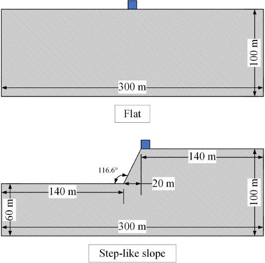
It has been shown in previous studies that the topography condition significantly impacts the seismic-induced damage to liquid storage tanks. Following the previous studies of Asgari et al. [29] and Lenti and Martino [31], two different topographic conditions were used for the investigated liquid storage tanks. As shown in Fig. (4), it was assumed that all tanks were constructed on flat ground. Then, a step-like slope similar to the study of Asgari et al. [27] was used. The obtained results from both cases were compared. After using sensitivity analysis, the author found that the amplification effect of the peak acceleration value at the top of the step-like slope is maximum when the slope reaches 116.6 degrees. Therefore, this study adopts the same topography condition.
2.4. Earthquake Records
Tso et al. [32] selected 45 earthquake records and studied their dynamic characteristics. They used the ratio of peak acceleration to peak velocity (A/V ratio) of earthquake records as the basis for classification. They showed that the records with a low A/V ratio (i.e., less than 0.8 g/m/s) characterized the earthquakes that occurred far from the source. In contrast, the records with a high ratio (i.e., A/V larger than 1.2 g/m/s) represented earthquakes near the source. The earthquake records that fell between the low and high ratios (i.e., medium range) had a source-to-site distance larger than the near-field records and smaller than the far-field records. In this study, according to their classification rules, three earthquake records were selected from each category to conduct the liquid storage tank's seismic analysis. Therefore, the earthquake records were selected to include all types of frequency content determined by Tso et al. [32]. In order to keep the liquid storage tanks within the elastic range, as has been done in previous studies [33-36], the peak ground acceleration (PGA) of the selected nine earthquake records was scaled to 0.25g. The details of selected earthquake records are presented in Table 5. The acceleration time history of the selected earthquake records is shown in Fig. (5).
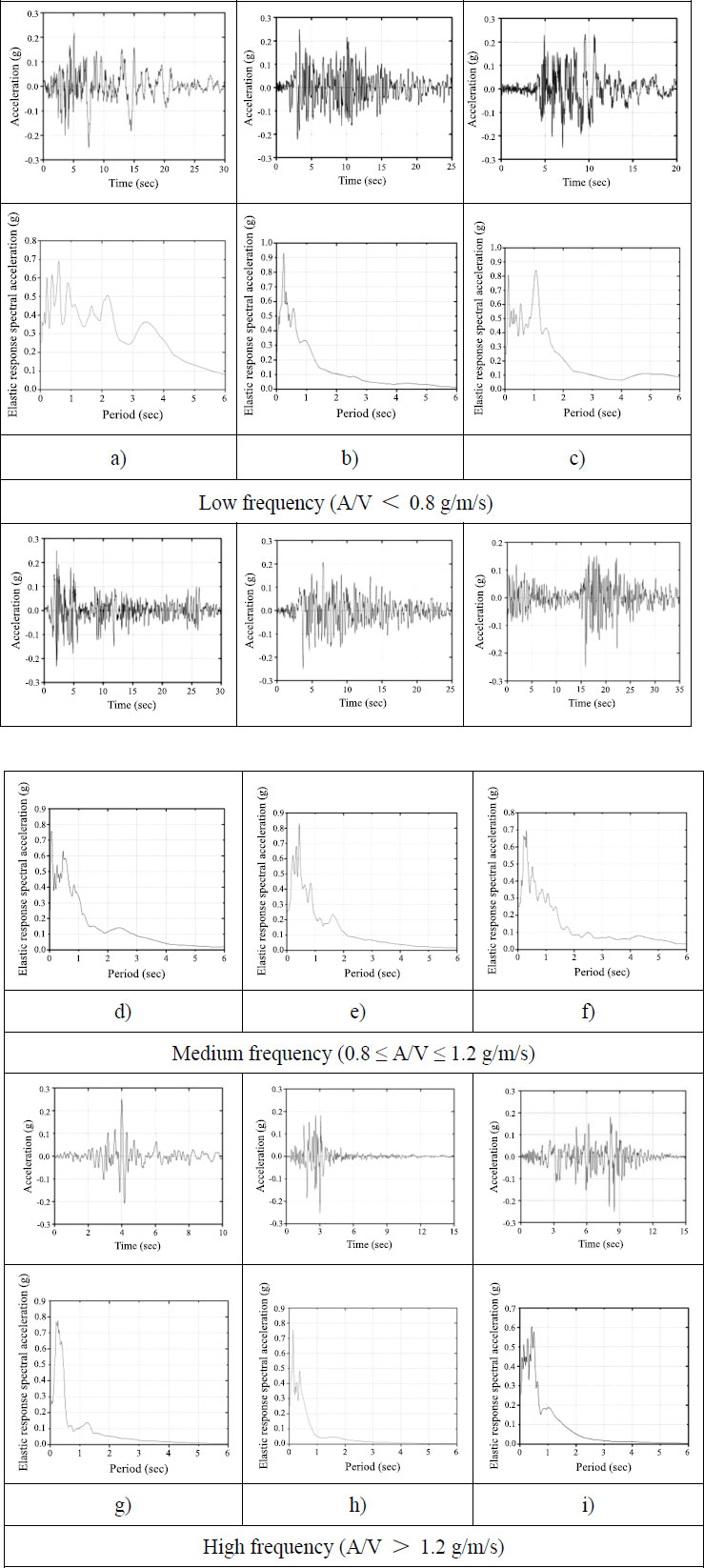
Table 5.
| No. | Earthquake | Date | Mag. | Source Dist. (km) | Max. Acc. (A) (g) | Max. Vel. (V) (m/s) | A/V Ratio (g/m/s) | Type |
|---|---|---|---|---|---|---|---|---|
| 1 | Long Beach, Calif. | 03/10/1933 | 6.3 | 59 | 0.097 | 0.237 | 0.41 | Low frequency (A/V < 0.8 g/m/s) |
| 2 | Lower, Calif. |
12/30/1934 | 6.5 | 58 | 0.160 | 0.209 | 0.77 | |
| 3 | San Fernando, Calif. | 02/09/1971 | 6.6 | 40 | 0.101 | 0.193 | 0.52 | |
| 4 | Imperial Valley, Calif. |
05/18/1940 | 6.6 | 8 | 0.348 | 0.334 | 1.04 | Medium frequency (0.8 ≤ A/V ≤ 1.2 g/m/s) |
| 5 | Ken County, Calif. |
07/21/1952 | 7.6 | 56 | 0.179 | 0.177 | 1.01 | |
| 6 | Borrego Mtn., Calif. |
04/08/1968 | 6.5 | 122 | 0.046 | 0.042 | 1.10 | |
| 7 | Parkfield, Calif. |
06/27/1966 | 5.6 | 7 | 0.269 | 0.145 | 1.86 | High frequency (A/V > 1.2 g/m/s) |
| 8 | Helena, Montana |
10/31/1935 | 6.0 | 8 | 0.146 | 0.072 | 2.03 | |
| 9 | San Fernando, Calif. |
02/09/1971 | 6.6 | 4 | 1.075 | 0.577 | 1.86 |
2.5. The Elements of Tank, Soil and Liquid
The element used to model the tank and soil in this study is PLANE 42 in ANSYS (18.2) software. PLANE 42 is mainly used for two-dimensional modelling to establish solid structures. The element mentioned above can be used to solve the problems of plane stress and plane strain or the problems of axial symmetry. The shape of the PLANE 42 element is quadrilateral, defined by four nodes. Each node has two degrees of freedom and can be translated in the x and y directions. The PLANE 42 element has plasticity, creep, swelling, stress stiffening, large deflection, and large strain capabilities. This element input data includes four nodes, a thickness (for the plane stress option only) and the orthotropic material properties. Orthotropic material directions correspond to the element coordinate directions. The pressures of this element can be inputted as surface loads on the element's face. The element stress directions are parallel to the element coordinate system. Surface stresses are available on any face. The area of the element must be nonzero, the element must lie in a global X-Y plane, and a triangular element may be formed by defining duplicate K and L node numbers. The PLANE 42 element has also been used in relevant literature to model soil and liquid storage tanks [13-15].
FLUID 79 in ANSYS (18.2) software is used to model the liquid in tanks. The FLUID 79 element is mainly used to simulate the liquid without net flow rate in various vessels, and it is particularly suitable for calculating hydro-static pressure and liquid-structure coupling interaction. For example, the acceleration, sloshing, and temperature effects can be effectively calculated. The FLUID 79 element contains four independent nodes; each node has only two degrees of freedom, which can be translated in the x and y directions. This element can achieve a dual effect of planar and axisymmetric elements in structural analysis. It is essential to point out that when using the FLUID79 element for modal analysis, only the reduced method can extract the structure's natural frequency. The element input data includes four nodes and the isotropic material properties. EX, which is interpreted as the “fluid elastic modulus”, should be the bulk modulus of the fluid (approximately 300,000 psi for water). The viscosity property (VISC) is used to compute a damping matrix for dynamic analyses (the typical viscosity value for water is 1.639 * 10-7 lb-sec/in2).
2.6. Constraints on Boundary Conditions
This study establishes the finite element models in a 2-dimensional environment. All the elements selected for modelling the storage tank, liquid in the tank and soil are also two-dimensional structures, and their degrees of freedom can only be translated in the x and y directions. Therefore, the z direction can be ignored when constraining the boundary conditions. In the natural environment, the liquid’s surface will shake freely under earthquake excitations, and the liquid’s surface will gradually return to the horizontal plane due to the constraint of gravity force. Therefore, it is necessary to conduct the master degrees of freedom for all nodes on the liquid’s surface to conduct super-element generation analyses. Moreover, given the characteristics of the FLUID 79 element, it is necessary to set the liquid surface on the plane where the origin is located during the modelling process; that is, the coordinates of the center point of the liquid surface are (0, 0).
The surface around the liquid in the tank and inside the tank wall are in contact. During the tank’s model establishment step, the nodes on their contact surfaces are also overlapped. Therefore, defining the coupled degrees of freedom at the interface is necessary. This aims to ensure that the forces on the liquid in the tank and the tank wall can be transferred to each other, forming a liquid-structure coupling interaction. Secondly, it can avoid the mutual penetration of their nodes of the liquid in the tank and the tank wall, which will cause errors in the analysis results. Moreover, this definition can enable the liquid in the tank to slide freely after being stressed, which conforms to the natural stress condition of the liquid. The parts to be defined are the left and right sides and the bottom of the liquid in the tank.
In the natural environment, the soil beneath the foundation is infinite. In order to fully consider the soil-structure coupling interaction and the dynamic response of the soil under seismic excitation, it is necessary to define all nodes on the elements on both the left and right sides of the soil model as constrained states. In this paper, their degrees of freedom in the x direction are constrained. For the degree of freedom of the nodes on the bottom element in the soil model, total constraints in the x and y directions are required to simulate so that the soil beneath the foundation is firmly bonded to the earth. The command to implement this in ANSYS (18.2) is D, Node, Lab, VALUE, VALUE2, NEND, NINC, Lab2, Lab3, Lab4, Lab5, Lab6. Applying constraints to the nodes does not affect the transfer of forces between them. The method employed for simulating the boundary conditions was based on the recommendation of ANSYS software and relevant literature [15, 27, 34]. The connection between the bottom of the storage tank and the soil was rigid. Moreover, the seismic excitation was based on recorded acceleration time histories and was applied horizontally to the structures.
2.7. Mesh Sensitivity Analysis
The element size used for the finite element analysis will affect the results’ accuracy. When considering the propagation characteristics of stress waves (i.e., earthquake waves), the element size should be fine enough to reflect the wave effect. The principle given by ANSYS software is that there are at least 20 elements in each wavelength along the wave propagation direction; the element size should be less than or equal to one-twentieth of the wavelength. Lee et al. [37] studied the application of finite element numerical simulation analysis to body wave propagation problems; he explicitly emphasized that if the actual size of the elements is less than one-eighth of the wavelength of the earthquake record, the attenuation and dispersion of the results can be controlled within 3%. The previous research on the liquid storage tank’s seismic response provided many bases for selecting the element size. Asgari et al. [27] set the tank, liquid and soil element sizes to one meter. Pranitha and Jayalekshmi [38] divided the tank and liquid element sizes into one meter and the soil into two meters. Maleki and Mansour [39] divided the tank and liquid element sizes into one meter and the soil into three meters. Therefore, following the previous studies, the element sizes of tank and liquid are determined to be one meter and that of soil to be one meter for this study.
2.8. Development of Finite Element Models
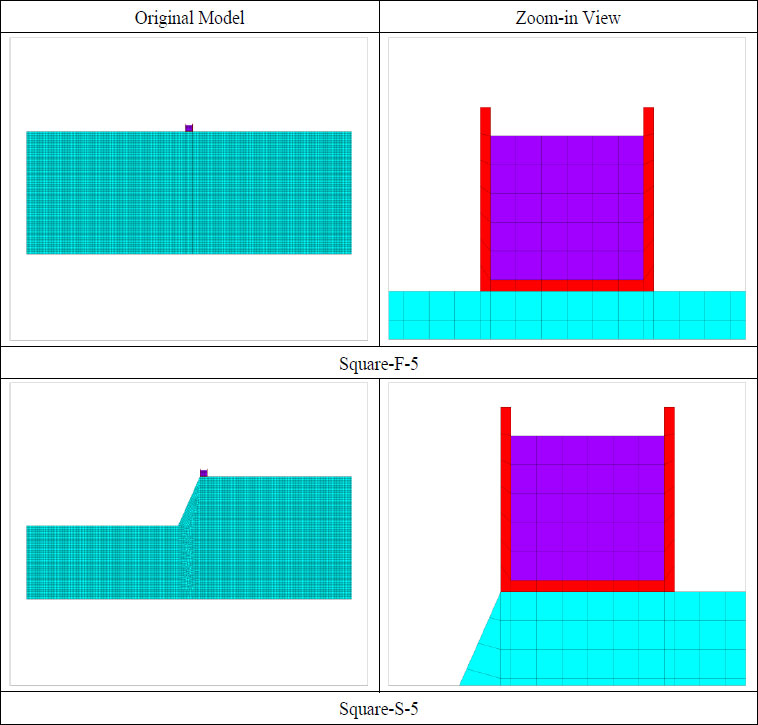
There are 18 finite element models used in this study, which comprise nine models of liquid storage tanks and two models of topography. These models were subjected to 9 different earthquake records. Therefore, a total of 162 finite element analyses were conducted. The detailed description of the 18 models is shown in Table 6. The finite element models with different dimensions constructed on flat and step-like slop soil are shown in Fig. (6). For brevity, only the finite element models of Square-F-5 and Square-S-5 are shown in the figure. In the figure, red elements represent the tank, purple elements represent the liquid in the tank, and green elements represent soil. Each complete triangle or quadrilateral represents an element, and the intersection of each line segment represents a node.
| Name | Topographic Condition | Type / Dimension | Diameter (m) | Height (m) | Thickness (m) | Aspect Ratio | Liquid Height (m) |
|---|---|---|---|---|---|---|---|
| Squat-F-0 | Flat | Squat | 6 | 3 | 0.3 | 0.5 | 0 |
| Squat-F-1 | Squat | 6 | 3 | 0.3 | 0.5 | 1 | |
| Squat-F-2 | Squat | 6 | 3 | 0.3 | 0.5 | 2 | |
| Square-F-0 | Square | 6 | 6 | 0.4 | 1.0 | 0 | |
| Square-F-3 | Square | 6 | 6 | 0.4 | 1.0 | 3 | |
| Square-F-5 | Square | 6 | 6 | 0.4 | 1.0 | 5 | |
| Slender-F-0 | Slender | 6 | 9 | 0.5 | 1.5 | 0 | |
| Slender-F-4 | Slender | 6 | 9 | 0.5 | 1.5 | 4 | |
| Slender-F-8 | Slender | 6 | 9 | 0.5 | 1.5 | 8 | |
| Squat-S-0 | Step-like slope | Squat | 6 | 3 | 0.3 | 0.5 | 0 |
| Squat-S-1 | Squat | 6 | 3 | 0.3 | 0.5 | 1 | |
| Squat-S-2 | Squat | 6 | 3 | 0.3 | 0.5 | 2 | |
| Square-S-0 | Square | 6 | 6 | 0.4 | 1.0 | 0 | |
| Square-S-3 | Square | 6 | 6 | 0.4 | 1.0 | 3 | |
| Square-S-5 | Square | 6 | 6 | 0.4 | 1.0 | 5 | |
| Slender-S-0 | Slender | 6 | 9 | 0.5 | 1.5 | 0 | |
| Slender-S-4 | Slender | 6 | 9 | 0.5 | 1.5 | 4 | |
| Slender-S-8 | Slender | 6 | 9 | 0.5 | 1.5 | 8 |
2.9. Type of Conducted Analysis
Transient dynamic analysis, also known as time history analysis, is mainly used to determine the dynamic response of the structure when the load changes with time according to any rule. The transient analysis can determine the structure's displacement, stress and strain changing with time under any combination of static load, transient load and sinusoidal load. It can provide feedback on the correlation between load and time, as well as the mass effect and damping effect. The method used in this study is the Full method in transient analysis. Compared with the Mode-superposition method, the Full method is easy to use, allowing all types of nonlinear characteristics, and it uses a complete matrix without considering the approximation of the mass matrix. Although this method can calculate all the displacement, stress, and strain changes of the structure in the seismic response simultaneously, it is time-consuming and requires efficient computers. Time history analysis can directly and effectively obtain structures' displacement, stress and strain parameters. As one of the most essential comparative parameters, almost all researchers have considered the liquid's sloshing wave height [40-42].
Similarly, the liquid storage tank bottom's base shear force is also a critical reference parameter to show the possible damage level under the action of an earthquake [43-45]. The stress on the inner side of the tank wall can show the magnitude and distribution of the tank's hydrodynamic pressure [46-48]. Many other parameters can be extracted to compare the storage tank's seismic response, such as the displacement of the tank wall, the overturning moment of the non-anchored tank and the warping force of the thin-walled steel tank [49-51]. The damping model used in this study was the Rayleigh damping model, which is available in the ANSYS software.
2.10. Validation of Finite Element Models
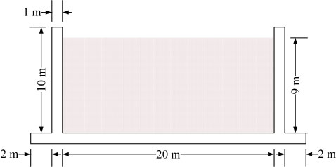
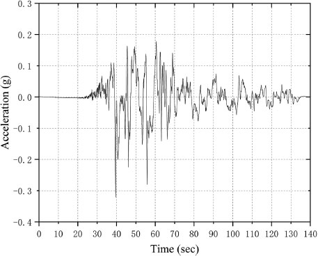
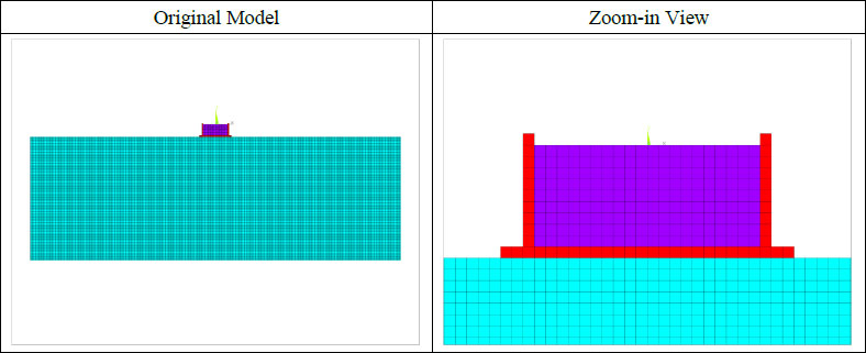
Livaoglu [52] investigated the seismic behaviour of a concrete, liquid storage tank by considering the liquid-structure-soil coupling interaction. The internal width of the liquid storage tank under the two-dimensional plane was 20 m, the tank wall’s height was 10 m, and the tank wall’s thickness was 1 m. The tank bottom’s thickness was also 1 m, and the circumference of the tank bottom was extended outward by 2 m. The height of the liquid was 9 m. The two-dimensional diagram of the liquid storage tank of Livaoglu [45] is shown in Fig. (7). The August 17, 1999, Kocaeli Earthquake (Yarimca station) was considered to be the source of seismic excitation. The adopted earthquake records’ acceleration time history is shown in Fig. (8).
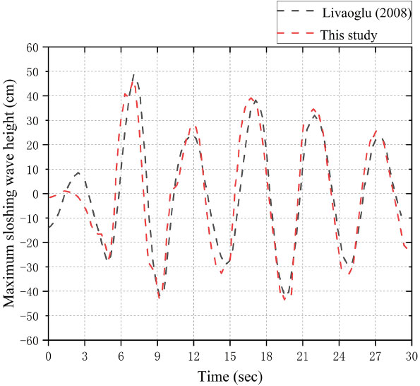
The finite element model used for validation is shown in Fig. (9). This study selected the maximum sloshing wave height of Livaoglu [52] to validate the accuracy of the established model. The comparison between the obtained results from this study and Livaoglu [52] is shown in Fig. (10). The two curves show good correlation and fitting, the base shear of the tank was estimated with less than 8% error, which can prove that the method of establishing finite element numerical simulation analysis model in this study is accurate, and can be used for further numerical studies.
4. RESULTS AND DISCUSSION
4.1. Dynamic Time History Analysis
4.1.1. Base Shear Forces Analysis of Tanks’ Bottom
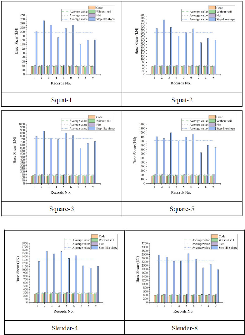
In this section, the base shear forces of tanks were calculated, and the obtained results were compared with the equation provided in Eurocode 8-part 4 (2004). The total base shear forces of each liquid storage tank were obtained by adding the shear forces of all nodes at the tank bottom. The calculation method for the total horizontal base shear force in Eurocode 8 is as follows:
 |
(1) |
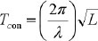
where mi is the impulsive part’s mass of the contained liquid, mw is the tank wall’s mass, mr is the tank roof’s mass, mc is the convective part’s mass of the contained liquid, Se (Timp) is the defined impulsive spectral acceleration, which is obtained by converting the elastic response spectrum, and its damping value is consistent with that described in section 2.3.3.1 of Eurocode 8 (ultimate limit state damping is 5%); Se (Tcon) is the defined convective spectral acceleration, which is obtained by converting the elastic response spectrum to a 0.5%-damped. Timp is the impulsive response’s natural periods, and Tcon is the convective response’s natural periods in seconds. The calculation method of Timp and Tcon are as follows:
 |
(2) |
 |
(3) |
 |
(4) |
 |
(5) |
 |
(6) |
 |
(7) |
 |
(8) |
 |
(9) |
 |
(10) |
 |
(11) |
 |
(12) |
For tanks with L/HL<1.333
 |
(13) |
For tanks with L/HL>1.333
 |
(14) |
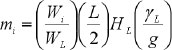
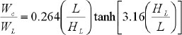
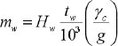
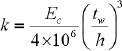
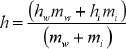
where L is the rectangular tank’s internal dimension parallel to the excitation direction, HL is storage tank’s design liquid depth, mw is rectangular tank wall’s mass per unit width, mi is contained liquid’s impulsive mass per unit width of the rectangular tank wall, Wi is liquid’s impulsive component equivalent weight, WL is the contained liquid’s total equivalent weight, γL is the density of contained liquid, g is acceleration due to gravity, Wc is liquid’s convective part equivalent weight, Hw is wall height (internal dimension), tw is average thickness of the tank wall, γc is concrete’s density, Ec is the concrete’s modulus of elasticity. The elastic response spectrums of the employed earthquake records for 5% and 0.5% damping values were calculated using SeismoSignal software. The graphs of the base shear force of different liquid storage tanks are exhibited in Fig. (11).
It can be seen from the results shown in Fig. (11) that the average base shear force obtained from finite element simulation is slightly greater than the method provided by Eurocode 8, and the differences range from 3.58% to 6.32%. When considering the soil-structure coupling interaction, the base shear force of the tanks constructed on flat topography is greater than that of tanks with fixed bases. The differences in the average base shear forces range from 9.25% to 10.64%. Compared with the liquid storage tanks’ average base shear force constructed on flat topography, the liquid storage tanks’ average base shear force constructed on step-like topography increased significantly. The differences in the average base shear forces range from 337.80% to 415.36%, with the largest difference between Square-F-3 and Square-S-3, in which the base shear is increased from 147.11 kN to 758.15 kN. The slightest difference is between Slender-F-4 and Slender-S-4, in which the base shear of the tank is increased from 302.13 kN to 1322.74 kN. It is worth mentioning that Asgari et al. [24] had a similar observation, and they pointed out that the amplification due to topographic irregularities had a considerable effect on the base shear responses and ranged from 200.81% to 575.11%. The results also show that the intensity of the storage tanks’ base shear force is related to the liquid’s and the tank wall’s mass. As the tank wall’s height and the contained liquid’s height increase, the base shear force also increases. It is also noted from the graphs that the base shear force of the liquid storage tanks, when constructed on step-like slope topography, is more sensitive to earthquake records with low- and medium-frequency contents. In other words, the base shear force values obtained from the excitation of high-frequency contents in earthquake records are slightly smaller than those with low or medium-frequency content.
4.1.2. Normal Stress Analysis in Tanks' Wall
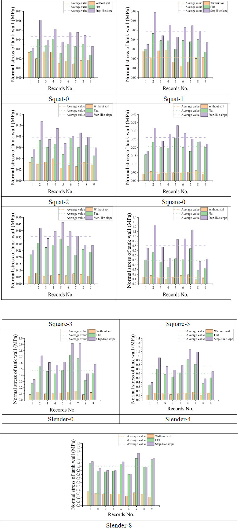
This section presents the normal stress in the tank wall along the excitation direction (i.e., the x direction). In order to make the results comparable, a node on the lower left side of the tank wall was selected as the observation point. It should be mentioned that the tank wall's normal stress near the observation point was the largest when the tanks were subjected to earthquake forces. Fig. (12) compares the magnitude of the tank wall's normal stress of different tank models, and the lines in the figure represent the average normal stress values under the excitation of nine earthquake records.
It can be seen from the results shown in Fig. (12) that when considering the soil-structure coupling interaction, the normal stress in the tank wall of liquid storage tanks constructed on flat topography is greater than that of liquid storage tanks with fixed bases. By comparing the same type of liquid storage tanks constructed on different topographies, it can be seen that tanks constructed on step-like slope topography have a larger normal strain than tanks constructed on flat topography. The differences in the average normal stresses range from 4.38% to 67.18%. For the three conditions of fixed-base, flat topography, and step-like slope topography, the tank wall's normal stress increases with the increase in liquid height. For fixed-base tanks, the differences in the average normal stresses range from 4.20% to 114.27%; the minor difference is between Squat-0 and Squat-1, increasing from 0.0206 MPa to 0.0215 MPa, and the most significant difference is between Slender-4 and Slender-8, increasing from 0.138 MPa to 0.296 MPa. For different aspect ratios (i.e., 0.5, 1.0 and 1.5), since the liquid height in the liquid storage tanks involved in this study is different, only the situation that the tanks do not contain liquid is compared. Under the above condition, with the increase of aspect ratio, the average normal stress in the tank wall also increases. For fixed-base tanks, the average normal stress of Squat-0, Square-0 and Slender-0 increases from 0.021 MPa to 0.048 MPa and from 0.048 MPa to 0.111 MPa, respectively. It is also noted from the graphs that the normal stress values of the Squat-type tanks are more sensitive to earthquake records with low-frequency content, especially for the step-like slope topography condition, such as the number 2 earthquake record. The normal stress values for Square-type tanks are more sensitive to earthquake records with low and medium frequency contents. For Slender-type tanks, the normal stress values are more sensitive to earthquake records with medium and high-frequency contents, such as number 6 and number 7 earthquake records, and the Slender-S-8 tank is more sensitive to number 7 and number 9 earthquake records.
4.1.3. Shear Stress Analysis in Tanks' Bottom
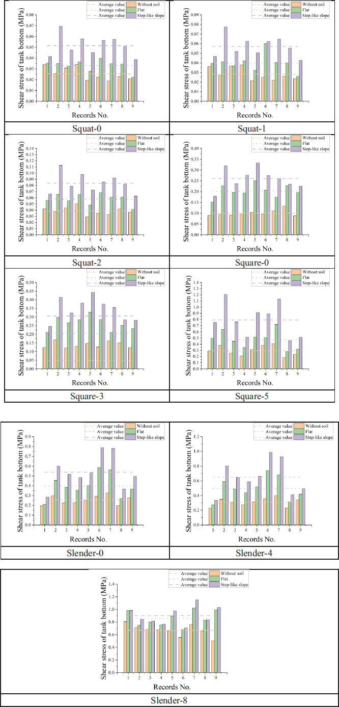
In this section, the shear stress at the tank bottom is presented. In order to make the results comparable, a node on the right side of the tank bottom was selected as the observation point. The shear stress in the tank bottom near the observation point was the largest when the tanks were excited by earthquake records. Fig. (13) compares the magnitude of the tank bottom’s shear stress of different tank models, and the lines in the figure represent the average shear stress values under the excitation of nine earthquake records.
It can be seen from Fig. (13) that when considering the soil-structure coupling interaction, the shear stress in the bottom of liquid storage tanks constructed on flat topography is greater than that of liquid storage tanks with fixed bases. The differences in the average shear stresses range from 27.88% to 101.86%. The slightest difference is between Slender-8 and Slender-F-8, which increased from 0.670 MPa to 0.857 MPa; the most significant difference is between Square-0 and Square-F-0, which increased from 0.100 MPa to 0.203 MPa. By comparing the same type of liquid storage tanks constructed on different topographies, it can be seen that tanks constructed on step-like slope topography have a larger shear stress than tanks constructed on flat topography. The differences in the average shear stresses range from 5.19% to 67.36%. The slightest difference is between Slender-F-8 and Slender-S-8, which increased from 0.857 MPa to 0.901 MPa; the most significant difference is between Square-F-5 and Square-S-5, which increased from 0.474 MPa to 0.793 MPa. In all three conditions of fixed-base, flat topography, and step-like slope topography, the shear stress in the tank bottom increases with the increase in liquid height. For fixed-base tanks, the differences in the average shear stresses range from 11.66% to 115.56%; the slightest difference is between Squat-0 and Squat-1, increasing from 0.025 MPa to 0.028 MPa, and the most significant difference is between Slender-4 and Slender-8, increasing from 0.311 MPa to 0.670 MPa. Since the liquid heights in this study are different for different aspect ratios (i.e., 0.5, 1.0 and 1.5), only the situations in which the tanks do not contain liquid are compared. Under the above condition, the tank bottom’s average shear stress increases with the increase of aspect ratio. For fixed-base tanks, the average shear stress of Squat-0, Square-0 and Slender-0 increases from 0.025 MPa to 0.100 MPa and from 0.100 MPa to 0.255 MPa, respectively. It is also noted from the graphs that the shear stresses of the Squat type tanks are more sensitive to earthquake records with low-frequency content, especially for the step-like slope topography condition, such as the number 2 earthquake record. The shear stress values for Square-type tanks are more sensitive to earthquake records with low and medium frequency contents. For Slender-type tanks, the shear stress values are more sensitive to earthquake records with medium and high-frequency contents, such as number 6 and number 7 earthquake records, and the Slender-S-8 tank is more sensitive to number 7 and number 9 earthquake records. The observed pattern of sensitivity of normal stress is similar to that of shear stress.
4.1.4. Displacement Analysis of Tanks' Wall
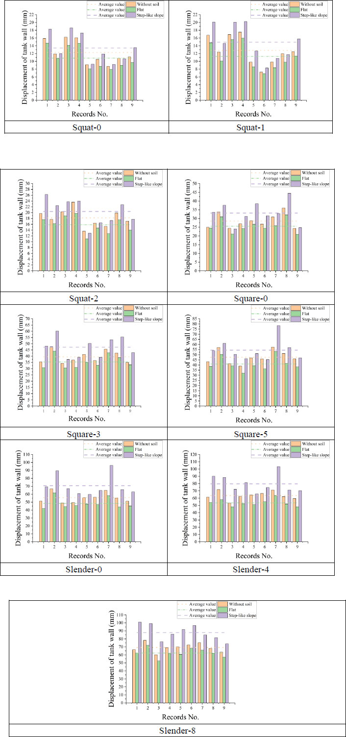
This section presents the top displacement of the storage tank wall in the x direction. In order to make the results comparable, a node on the top left of the tank wall was selected as the observation point. Fig. (14) compares the magnitude of the tank wall’s displacement of different tank models, and the lines in the figure represent the average displacement values under the excitation of nine earthquake records.
It can be obtained from Fig. (14) that when considering the soil-structure coupling interaction, the tank wall’s displacement constructed on flat topography is less than that of tanks with fixed bases. The differences in the average displacements range from 9.90% to 15.76%. The slightest difference is between Slender-8 and Slender-F-8, which decreased from 69.248 mm to 62.396 mm; the most significant difference is between Slender-4 and Slender-F-4, which decreased from 63.657 mm to 53.626 mm. By comparing the same type of liquid storage tanks constructed on different topographies, it can also be observed that tanks constructed on step-like slope topography have a greater wall displacement than tanks constructed on flat topography. The differences in the average displacements range from 23.84% to 48.69%. The slightest difference is between Squat-F-0 and Squat-S-0, which increased from 10.84 mm to 13.43 mm; the most significant difference is between Slender-F-4 and Slender-S-4, which increased from 53.63 mm to 79.73 mm. For the three conditions of fixed-base, flat topography and step-like slope topography, the tank wall’s displacement increases with the increase in the liquid height. For fixed-base tanks, the differences in the average displacements range from 4.21% to 42.22%; the slightest difference is between Squat-0 and Squat-1, increasing from 12.27 mm to 12.79 mm, and the most significant difference is between Squat-1 and Squat-2, increasing from 12.79 mm to 18.18 mm. Since the liquid heights in this study are different for different aspect ratios (i.e., 0.5, 1.0 and 1.5), only the situations in which the tanks do not contain liquid are compared. Under the above condition, with the increase of aspect ratio, the displacement of the tank wall also increases. It is also noted from the graphs that the displacement values of the Squat-type tanks are more sensitive to earthquake records with low-frequency content. For Square-type tanks, the sensitivity to frequency contents of earthquake records is not particularly obvious; square-0 type and Square-5 type tanks are more sensitive to number 7 earthquake records with high-frequency content, and Square-3 type tanks are more sensitive to number 2 earthquake records with low-frequency content. For Slender-type tanks, Slender-0 type and Slender-4 type tanks are not sensitive to medium frequency content earthquake records, and Slender-8 type tanks are sensitive to low frequency and medium frequency content earthquake records.
CONCLUSION
This study investigated the seismic response characteristics of 18 liquid storage tank models using the finite element numerical simulation method. Three different tank sizes, three different liquid heights, two types of topography conditions, and nine earthquake records were considered. The base shear force, normal stress in the tank wall, shear stress in the tank bottom and maximum displacement of the tank wall of finite element models were calculated and presented.
Compared with flat topography, step-like slope topography slightly increased the value of normal stress in the tank wall. The same was true for the shear stress in the tank bottom and the tank wall displacement. For normal stress in the tank wall, the average increase ranged from 4.38% to 67.18%. Under seismic excitations, the average increase in the shear stress ranged from 5.19% to 67.36%. Similarly, the average increase in tanks' wall displacements ranged from 23.84% to 48.69%. Results showed that the step-like slope topography significantly affected the tanks' base shear force. Compared with tanks constructed on flat topography, the increase in the average base shear forces ranged from 337.80% to 415.36%; the most significant difference was between the base shear forces of Square-F-3 and Square-S-3 that increased from 147.11 kN to 758.15 kN; the slightest difference was between Slender-F-4 and Slender-S-4, in which the base shear increased from 302.13 kN to 1322.74 kN. Comparing the results of the analytical equation in Eurocode 8 with the results of the finite element method showed that the base shear force values of the analytical equation were slightly less than that of the tanks with fixed-base and the tanks constructed on flat topography. However, the base shear forces obtained for the step-like slope topography from finite element simulations were significantly larger than those of Eurocode 8. In short, the step-like slope topography increased the risk of earthquake damage to liquid storage tanks. Therefore, special construction conditions, such as irregular topography, should be considered in the seismic design of liquid storage tanks.
Further analysis can be conducted in the future to deal with the current study's limitations. Using 3D models instead of the employed 2D models, considering bi-directional excitations, vertical excitations, steel tanks rather than concrete tanks, and different boundary conditions can enhance the findings and improve the generalization of obtained results.
LIST OF ABBREVIATIONS
| mi | = The impulsive part’s mass of the contained liquid (kg) |
| mw | = The tank wall’s mass (kg) |
| mr | = The tank roof’s mass (kg) |
| mc | = The convective part’s mass of the contained liquid (kg) |
| Se (Timp) | = The defined impulsive spectral acceleration, which is obtained by converting the elastic response spectrum, and its damping value is consistent with that described in section 2.3.3.1 of Eurocode 8 (ultimate limit state damping is 5%) |
| Se (Tcon) | = The defined convective spectral acceleration, which is obtained by converting the elastic response spectrum with the value of 0.5%-damped |
| Timp | = The impulsive response natural periods (s) |
| Tcon | = The convective response natural periods (s) |
| L | = The rectangular tank’s internal dimension parallel to the earthquake’s direction being investigated (m) |
| HL | = The storage tank’s design liquid depth (m) |
| Wi | = The liquid’s impulsive component equivalent weight (kg/m3) |
| WL | = The contained liquid’s total equivalent weight (kg/m3) |
| γL | = The density of contained liquid (kg/m3) |
| Wc | = The liquid’s convective part equivalent weight (kg/m3) |
| Hw | = The wall height (internal dimension) (m) |
| tw | = The average thickness of the tank wall (mm) |
| γc | = The concrete’s density (kg/m3) |
| Ec | = The concrete’s modulus of elasticity (GPa) |
CONSENT FOR PUBLICATION
Not applicable.
AVAILABILITY OF DATA AND MATERIAL
The data cannot be shared openly but are available on request from the corresponding author [M.Y].
FUNDING
This work was financially supported by (The Natural Science Foundation of the Department of Science and Technology of Ningxia Hui Autonomous Region) (Grant numbers 2022AAC03697 and 2023AAC03817).
CONFLICT OF INTEREST
The authors declared no conflict of interest, financial or otherwise.
ACKNOWLEDGEMENTS
The authors are thankful for the provided supports by the Universiti Teknologi Malaysia to conduct the current study.

