All published articles of this journal are available on ScienceDirect.

Thermal Waste Replacement as a Sustainable Approach to Reinforced Concrete Beam Design: A Finite Element Study
Authors Info & Affiliations
Abstract
Introduction
The escalating global demand for infrastructure underscores the need for increased construction material use, particularly in concrete, a fundamental component of the construction sector. However, conventional aggregate extraction methods pose significant environmental challenges, including river pollution from sand extraction and deforestation due to rock quarrying. Repurposing industrial waste materials as sustainable concrete components is crucial to address the depletion of natural resources from sand and gravel use. In Malaysia, where electricity production relies on coal, power generation produces waste materials, specifically bottoms such as fly ash and coal combustion by-products in power plants. Disposing of this by-product, primarily in open landfills, raises significant environmental hazards for local communities, impacting health and safety.
Aims
To address environmental concerns related to natural material depletion and by-product waste abundance, this study explores recycling coal bottom ash and fly ash from coal power plants as part of concrete materials in reinforced concrete beams. Additionally, the paper uses nonlinear analysis in ABAQUS software to explore the structural performance and behavior of RC beams incorporating high volumes of coal ash as replacements for fine and coarse aggregates.
Methods
Six replacements spanning 50% to 100% were tested alongside 20% cement substitution with fly ash. The mixture includes a 50% replacement of natural fine aggregates with fine coal bottom ash and a 50% replacement of natural coarse aggregates with coarse coal bottom ash. The materials replacement calculation was based on the materials' volume due to the differences in density between the waste material and conventional materials. On the other hand, mechanical properties were assessed through four-point bending load tests, recording deflections, loads, and crack patterns. Finite element analysis models using ABAQUS were also performed to predict the beam behavior and validated against experimental responses. Besides, the parametric study with different beam lengths was also performed to observe the beam behavior and validate the input.
Results
The inclusion of 100% coarse coal bottom ash (CCBA) and 100% fine coal bottom ash (FCBA) in the concrete mix resulted in significant enhancements in structural performance, surpassing the control RC beam with an ultimate load of 88 kN and a maximum deflection of 18.87 mm. The successful development of a finite element model using ABAQUS software for finite element analysis (FEA) showcases the capability of simulation tools in predicting structural behavior with differences within a 10% range. Besides, the parametric study revealed that longer beams exhibited more prominent cracks and severe failure, indicating the reliability of the input parameters in FEA.
Conclusion
This study highlights the effectiveness of the proposed approach in enhancing RC beam performance. The findings validate the simulation tool's potential in predicting structural behavior and shed light on the complexities of concrete behavior under varying conditions. As future designs advance, these insights will inform more accurate and robust structural assessments, fostering innovation and improved engineering solutions.
1. INTRODUCTION
The global demand for infrastructure is rapidly growing, leading to an increased need for construction materials [1]. Concrete, a fundamental component of the construction sector, comprises fine and coarse aggregates, cement, and water [2]. However, mining aggregates poses environmental challenges like river pollution from sand extraction and deforestation due to rock quarrying [3, 4]. Repurposing industrial waste materials as sustainable concrete components is crucial to counter the depletion of natural resources caused by sand and gravel use [1].
Concurrently, in Malaysia, electricity production relied on coal as a power source. The generation of electricity in this sector produces waste materials, specifically bottom ash, and fly ash, as by-products of coal combustion in power plants [5, 6]. The increasing volume of waste produced from power plants is often disposed of in landfills, raising concerns, especially on environmental issues [7]. In dry bottom boilers, pulverized coal combustion generates approximately 80 to 90% of unburned or entrained ash as fly ash, while the remaining 10 to 20% is in the form of dry bottom ash [5]. Bottom ash is generally in dark brown, granular, and porous material stored in water-filled hoppers at furnace bases [8].
The current method of coal ash disposal, predominantly in open landfills, poses significant environmental hazards for local communities, impacting both health and safety [9]. Researchers worldwide have shown an interest in the potential of Coal Bottom Ash (CBA) as an eco-friendly and alternative material to replace traditional concrete. Previous research highlighted that CBA exhibits properties that make it a viable substitute for natural aggregates, as observed in studies by [10, 11]. In addition to that, [12] found that adding 20% fly ash to cement enhances concrete strength. Experimental work to understand concrete performance with different waste material variables demands considerable time and cost [13]. Finite Element (FE) models can streamline the process and reduce costs to study a range of innovative design solutions [14]. Finite Element Analysis (FEA) is an invaluable assessment tool that offers insights into cracking and load-deflection curves and enables parametric studies that are not feasible through experiments.
Recycling CBA from coal power plants as part of concrete materials in reinforced concrete (RC) beams is explored to mitigate the environmental concerns related to the depletion of natural materials and the abundance of by-product waste. This study primarily examines the replacement of significant CBA volumes as fine and coarse aggregates to assess concrete and RC beam mechanical performance and behavior. This paper also discussed the structural performance and behavior of RC beams incorporating CBA as a fine and coarse aggregate replacement using nonlinear analysis in ABAQUS software. The unique aspect of this paper lies in its introduction of a finite element analysis for material replacement in concrete. Typically, research has focused on the experimental phase, but this research goes further by incorporating modeling, allowing for exploration of the inputs and parameters associated with recycled materials.
2. LITERATURE REVIEW
Various authors conducted numerous studies that yielded substantial information regarding the characteristics and performance of concretes with aggregate replacement. As the demand for concrete increases, so does the demand for aggregate in various industries. Recognizing the importance of sustainable development, the Malaysia Prime Minister’s Department in 2017 emphasized the need to minimize the use of raw materials to curb aggregate growth, aligning with the principles of sustainable building development. The New Economic Model (NEM) introduced by Malaysia in 2009 further underscores the commitment to sustainable development, focusing on three key objectives: high profit, inclusivity, and sustainability. Therefore, this section delves into discussions on natural aggregate in concrete, the coal ash industry, and the application of the finite element method in the analysis of modified RC beams.
2.1. Natural Aggregate in Construction
Concrete, a homogeneous blend of cement, fine aggregates, coarse aggregates, and water, undergoes hardening over time. The evaluation of concrete quality encompasses its durability and physical, structural, and mechanical properties [15]. The extensive global use of aggregates raises a concern about depleting natural resources, posing challenges to environmental sustainability [16]. Aggregate production involves extracting and processing raw materials into usable products, transporting them to the point of use, and addressing the reclamation of extracted waste or quarries [17]. Natural river sand is the most common fine aggregate used in the industry. The increasing demand for it has led to increased sand mining in riverbeds, resulting in deforestation, habitat degradation, and soil and water pollution [4].
The most visible environmental impact of aggregate extraction is the transformation of landscapes, converting agricultural and undeveloped land into quarries or pits [18]. River sand mining exacerbates issues such as heavy floods due to alterations in river flow direction and adverse effects on biological diversity [17]. Consequently, these problems can adversely affect the endangered species and result in habitat loss. Hence, it is imperative to identify alternative materials to substitute natural river sand to promote sustainable development within the country.
2.2. Coal Bottom Ash
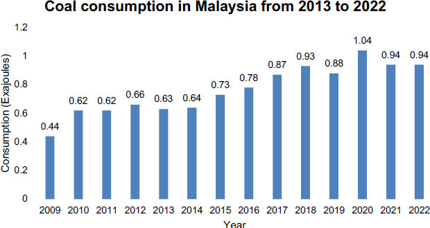
Coal is the predominant fuel employed for electricity generation in thermal power plants. It has been consistently proven to be one of the most cost-effective sources of energy production for numerous countries, including Malaysia, as presented in Fig. (1). As per estimates from the World Coal Institute (WCI), coal-powered plants currently contribute to 41% of global electricity, and this reliance on coal is projected to persist, reaching 44% of global electricity by 2030 [19]. The continuous exploration and use of coal are driven by population growth and the increasing demand for a higher quality of living, necessitating elevated energy production levels.
CBA has become a subject of significant interest as a sustainable substitute for natural fine aggregate commonly used in concrete mixes. The utilization of CBA in concrete mixtures underscores the importance of understanding its characteristics and impact on the properties of various types of concrete [20]. Numerous experimental studies have indicated that CBA when used in appropriate proportions, can offer advantages in terms of workability, increased concrete strength, and enhanced durability [21]. Research reports as per [22], highlight that incorporating bottom ash as a replacement for sand in concrete affects various aspects, including workability, setting times, water loss through bleeding, bleeding rate, plastic shrinkage of fresh concrete, as well as the density, strength, porosity, and durability of the hardened mass.
Consequently, several researchers have conducted tests to assess the properties of concrete incorporating CBA as an aggregate replacement [23] and demonstrated that CBA concrete's mechanical properties remain relatively comparable with conventional concrete when up to 20% replacement is employed. Additionally, [22], which explored the inclusion of CBA as aggregate replacement in concrete with varying replacement levels (0%, 20%, 30%, 50%, 75%, and 100%), revealed a significant increase in compressive strength after 28 days. The delayed hydration of CBA and the pozzolanic activity of bottom ash concrete mixes contributed to this observed improvement, and reducing the free water-cement ratio further enhanced concrete strength. Since most of the research focuses on replacing fine aggregate, this research aims to replace CBA as fine and coarse aggregates to elucidate the properties and behavior of concrete and reinforced concrete (RC) beams.
In addition, this research also incorporates the use of fly ash to augment the mechanical properties of both concrete and reinforced concrete beams. CBA alone does not suffice to enhance the mechanical properties; hence, introducing a superior material is necessary to achieve improved performance in the concrete. Fly ash primarily consists of spherical, solid, hollow, and predominantly amorphous particles, including coarse and powdery components. Additionally, fly ash serves as an excellent binding material [24]. Typically, the particle sizes of fly ash range from 1 to 100 µm.
Concrete incorporating fly ash as a cement replacement exhibits notable characteristics such as high workability, low hydration heat, adequate early and later-age strength, low drying shrinkage, and minimal cracking [25]. According to [26], adding fly ash to concrete, which contributes to increased durability, alters the pore structure, resulting in decreased porosity and permeability of the concrete. Consequently, this modification enhances the concrete's resistance to chloride intrusion. For instance, [12] investigated the replacement of fly ash in cement with an additional superplasticizer and a constant water-cement ratio. They concluded that a mix with 20% fly ash as a cement replacement exhibited the highest strength compared to other mixes. Furthermore, in the study by [27], the replacement of fly ash in cement revealed that adding 20% fly ash in concrete can slow down the cement hydration process during the nucleation and growth stage. This is attributed to the ability of aluminate ions dissolved from the fly ash to reduce the number of heterogeneous nucleation sites of C-S-H and inhibit the growth of the compound. Hence, in this study, 20% fly ash was utilized as a cement replacement to enhance the workability and strength of concrete. In conclusion, integrating coal combustion waste in concrete offers multifaceted benefits with potential environmental, economic, and social implications.
Utilizing coal combustion waste in concrete diminishes the volume of waste dumped in landfills, mitigating the environmental hazards and promoting responsible waste management. By substituting natural materials with coal combustion waste, the demand for natural resources is reduced and can lead to cost savings, as it provides an alternative to conventional materials.
2.3. Finite Element Analysis
Finite Element Analysis (FEA) was employed in this study to conduct a nonlinear static analysis incorporating both material and geometric nonlinearities. ABAQUS, a widely used commercial finite element program, was chosen for its robust capability to construct and analyze complex models effectively across various real-world applications. ABAQUS is adept at representing linear and nonlinear mechanical behaviors of materials such as concretes, composite materials, and complex geometries [28]. Several commercial software options for nonlinear analysis, including ABAQUS, ADINA, ANSYS, and NASTARAN, necessitate appropriate input values and a sound technological understanding. ABAQUS and ANSYS stand out for their user-friendly graphical interfaces, robust grid-division features, extensive material-element libraries, and contact-connection types [29]. These features make it well-suited for addressing the complexities of engineering challenges and are frequently employed in the dynamic analysis of single-phase media.
3. METHODOLOGY
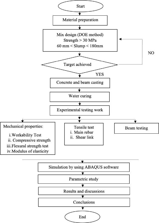
The study's flow chart, as depicted in Fig. (2), outlined the sequential steps of the research. It began with preparing materials, including Coal Bottom Ash (CBA), Fly Ash (FA), cement, and aggregates. Subsequently, the target strength was determined using the Department of Environment (DOE) method. Following this, six mixtures of concrete beams were cast and underwent a 28-day curing process. A series of tests were then conducted to explore the mechanical properties of the concrete, encompassing assessments of workability, compressive strength, flexural strength, and the modulus of elasticity. Additionally, a tensile test was performed to ascertain the yield strength of the steel used. The subsequent phase involved a nonlinear finite element analysis simulation through the ABAQUS software. The simulation results were subsequently compared to the experimental findings. Besides, a parametric study using different lengths of beams was conducted to assess the sensitivity of the stress-strain response to variations in the input material characteristics.
3.1. Material Preparation - Cement
Ordinary Portland Cement was Type 1 Portland cement by MS EN 197-1:2014 (2014). This standard for Portland cement is suited for all ordinary purposes. The highest constituent of Portland cement is calcium oxide, which is 62%, followed by 20% silica oxide, as shown in Table 1. Alumina and iron oxide percentages are 6% and 3%, respectively. Calcium oxide, also known as lime, reacts with water during the hydration process to form calcium hydroxide (CaOH2). Besides, an early strength development of concrete also contributes to the presence of calcium oxide in the cement.
3.2. Fly Ash
Fly Ash (FA) is a waste product coal-fired power plants generate. Table 2 details the characteristics of the FA. The FA in this study was acquired from the Tanjung Bin Power Plant located in West Malaysia. It originated from the finer and lighter coal ashes that escaped with the flue gases and were extracted in electrostatic precipitators before being released into the atmosphere. The particles of FA were smaller than those of CBA. In this study, FA was utilized as a 20% replacement for cement in the mixture. Before use, the FA was stored in a dry location to ensure material quality and the dryness of the FA. From the table, the overall percentage of SiO2, Al2O3, and Fe2O3 in FA was approximately 78.44%, categorizing it as a Class F material according to the ASTM C 618 − 12a (2012) standard.
| Constituent | Percentage by Weight (%) |
|---|---|
| Silica, SiO2 | 19.8 |
| Alumina, Al2O3 | 5.6 |
| Iron Oxide, Fe2O3 | 3.4 |
| Calcium, CaO | 62.7 |
| Magnesia, MgO | 1.2 |
| Sodium, N2O | 0.02 |
| Phosphorus, P2O5 | 0.1 |
| Loss of Ignition, LOI | 2.1 |
| Lime Saturated Factor | 1.0 |
| Chemical Composition | Percentage (%) |
|---|---|
| Silicon dioxide (SiO2) | 47.3 |
| Aluminum oxide (Al2O2) | 23.2 |
| Iron oxide (Fe2O3) | 7.94 |
| Calcium oxide (CaO) | 10.70 |
| Potassium oxide (MgO) | 1.50 |
| Sodium oxide (Na2O) | 3.91 |
| Potassium oxide (K2O2) | 1.4 |
| Titanium dioxide (TiO2) | 2.87 |
| Sulfur trioxide (SO3) | 0.75 |
| Loss of ignition (LOI) | 0.43 |
3.3. Coal Bottom Ash
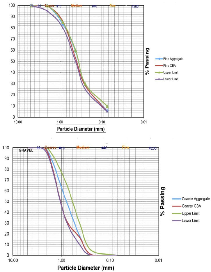
CBA was collected from the Tanjung Bin Power Plant and sieved to a 10 mm to 20 mm size for coarse aggregate replacement named Coarse Coal Bottom Ash (CCBA). The portion passing through a 4.75 mm sieve was used for fine aggregate replacement named Fine Coal Bottom Ash (FCBA). Sieve analysis was conducted according to the BS EN 933-2 standard. Fig. (3) displays fine and coarse CBA particle distribution, demonstrating their adherence to the standard's upper and lower limits. Tables 3 and 4 present the physical and chemical properties of the CBA used in this study. The primary chemical constituents are Silica, Alumina, and Iron, with the cumulative SiO2, Al2O3, and Fe2O3 content exceeding 50%, aligning with Class C criteria as per ASTM 618–03 standards.
| - | CBA | Natural Coarse Aggregates | Natural Fine Aggregates |
|---|---|---|---|
| Specific Gravity | 1.88 | 2.7 | 2.62 |
| Water Absorption, (%) | 11.61 | 4.64 | 9.29 |
| Fineness modulus | 3.44 | - | 2.65 |
| Composition | Percentage (%) |
|---|---|
| Silicon Oxide (SiO2) | 34.7 |
| Aluminium Oxide (Al2O3) | 12.3 |
| Iron Oxide (Fe2O3) | 9.93 |
| Calcium Oxide (CaO) | 5.60 |
| Potassium Oxide (MgO) | 0.79 |
| Sodium Oxide (Na2O) | 0.75 |
| Potassium Oxide (K2O) | 0.88 |
| Titanium Dioxide (TiO2) | 0.86 |
| Sulphur Trioxide (SO1) | 2.75 |
| Mix | Cement (%) | Fly Ash (%) | Coarse Aggregate (%) | Fine Aggregates (%) | Water/Cement Ratio | Water/Binder Ratio | ||
|---|---|---|---|---|---|---|---|---|
| Granite | CCBA | Sand | FCBA | |||||
| Control | 100 | 0 | 100 | 0 | 100 | 0 | 0.5 | 0.59 |
| Control with 20% Fly ash |
80 | 20 | 100 | 0 | 100 | 0 | ||
| 100% CCBA 100% FCBA |
80 | 20 | 0 | 100 | 0 | 100 | ||
| 100% CCBA 50% FCBA |
80 | 20 | 0 | 100 | 50 | 50 | ||
| 50% CCBA 100% FCBA |
80 | 20 | 50 | 50 | 0 | 100 | ||
| 50% CCBA 50% FCBA |
80 | 20 | 50 | 50 | 50 | 50 | ||
3.4. Mix Proportion
For this study, six mixtures utilizing CBA as fine and coarse aggregates were prepared, as presented in 252 Table 5. A constant 20% fly ash was employed as a cement replacement across all mixes. Two control 253 mixtures were included: one with 20% fly ash and another without fly ash or CBA. The mix designs were 254 created using the DOE method stated in BS EN 206 -1 to target a 28-day curing period with a strength of 30 MPa.
Due to the differing densities of these materials, natural coarse aggregate (granite) and fine aggregate (sand) were replaced by CBA using a volume-based approach. Replacement proportions of fine and coarse aggregates ranged from 50% to 100%, all maintained at a water-cement ratio of 0.5.
3.5. Beam Preparation
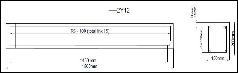
RC beams adhering to the dimensions outlined in the BS EN 1992-1-1 standard were designed. The beams measured 1500 mm × 200 mm × 150 mm and were reinforced with double 4Y12 high-tensile bars and R6 mild steel round bar stirrups spaced at 100 mm intervals. Fig. (4) provides details of the beam's configuration. These RC beams were cast, allowed to cure for 28 days, and then subjected to a flexural four-point load test to evaluate deflection and cracking patterns. A concrete cube was also prepared for each mix design batch to assess compressive strength.
3.6. Casting Procedure
A mechanical mixer with a capacity of 20 liters and a rotating speed of 80 rpm was employed for the mixing process. The natural fine and coarse aggregates were initially in a saturated-surface-dry condition and were poured into the mixer and mixed for 2 minutes. Then, cement was introduced and mixed thoroughly for about 5 minutes until a homogeneous condition was attained. Finally, the calculated amount of water for hydration was introduced into the mixer and mixed for another 10 minutes. The homogeneous mixture was poured into the mold and compacted using a vibrating table for 10 seconds. The fresh concrete was hardened for 24 hours before being removed from the mold for curing. The concrete mixture was allowed to water curing for 28 days before testing.
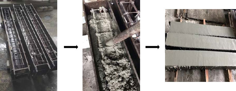
Based on the calculations, the primary rebar and shear link were initially cut to size for the beam. The shear links were connected to the primary rebars using a wire twister. After settling the rebars, all the materials were prepared by weighing them the day before casting. Then, beam molds for the casting process were prepared. To facilitate the demolding process, the surface of the used molds was coated with grease oil. Next, the tied rebar was placed in the beam molds. Then, the materials were mixed using a mixing machine and immediately placed into the molds to prevent them from hardening. In the mold, three layers of freshly mixed concrete were poured. Each layer of concrete was vibrated using a vibrating machine to ensure that the beams had no trapped air. Then, the beams were allowed to harden for 24 hours before being demolded for curing. In the final stage of this process, the beam was cured for 28 days with a wet canvas. The process of beam casting is presented in Fig. (5).
3.7. Modelling of Reinforced Concrete Beam
The analysis modules, specifically ABAQUS/ Standard and ABAQUS/Explicit, constitute the pivotal components in ABAQUS Software (CAE ASSISTANT, 2022). Within ABAQUS, there exist three constitutive models for capturing the inelastic behavior of concrete: the Concrete Smeared Cracking Model (CSCM), the Concrete Damaged Plasticity (CDP) model, and the Brittle Cracking Concrete (BCC) model [30].
This research employed the CDP model due to its comprehensive representation of three-dimensional nonlinear inelastic behavior in concrete. This model encompasses various aspects such as confinement and damage mechanisms and compressive, tensile, and plastic characteristics within the inelastic range. The CDP model is a suitable choice for simulating concrete materials primarily because it can effectively model elastic stiffness loss resulting from plastic strains in compression and tension.
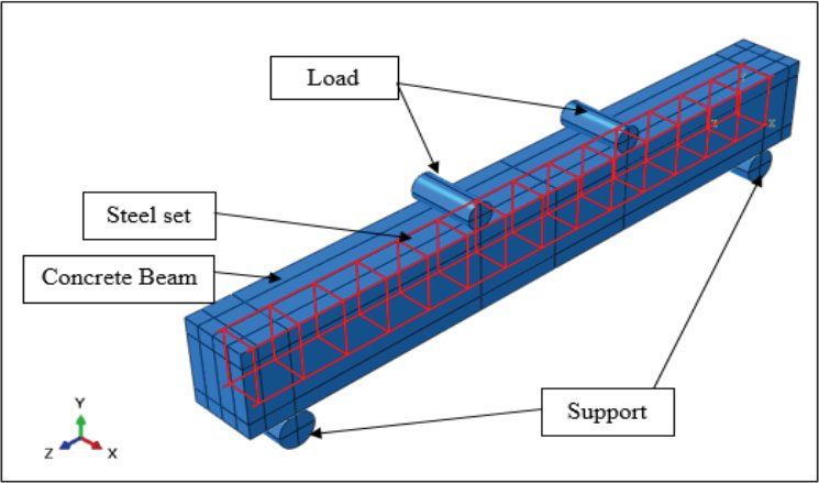
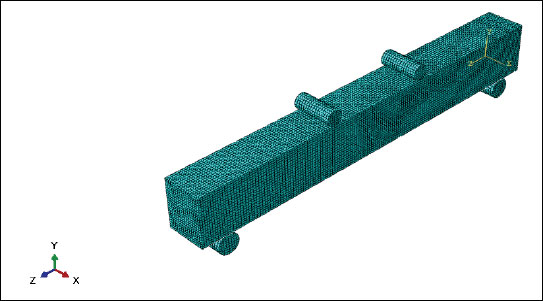
The finite element analysis (FEA) of the RC beams involved several key steps. Firstly, the geometry of each element was accurately constructed using ABAQUS components, encompassing solid rectangles, loads, supports, and steel reinforcements. These elements were meticulously positioned and assembled. Fig. (6) illustrates the assembled beam's configuration. Material properties were assigned to each element; for steel, these properties included Young's Modulus, Poisson's Ratio, Yield Stress, and Plastic Strain [15]. The optimization process for input in ABAQUS involves consideration of five parameters: dilation angle (φ), flow potential eccentricity (e), the ratio of compressive strength under biaxial loading to uniaxial compressive strength (fb0/fco), the ratio of the second stress invariant on the tensile meridian to that on the compressive meridian (Kc), and viscosity parameter (µ) [31]. Table 6 tabulated the specific material properties employed in the analysis.
| Dilation Angle () | Eccentricity (Ɛ) |
Under Biaxial Loading/ Unaxial Strength ( / ) |
Compressive Meridian (Kc) | Viscosity Parameter (µ) |
|---|---|---|---|---|
| 40 | 0.1 | compressive 1.16 | 0.6667 | 0 |
The material properties were calibrated to ensure that the numerical model accurately represents the real-world behavior of materials. This is crucial for obtaining simulation results that can be relied upon to make engineering decisions. The calibration of the dilation angle in ABAQUS modeling is a critical step to ensure that the numerical simulation accurately represents real-world material or structure behavior. It is a parameter that influences the expansion or contraction of a material in response to deformation. It plays a significant role in capturing materials' nonlinear and inelastic behavior, especially concrete. Different dilation angle values were tested during calibration while keeping other parameters at their default values. In this study, the dilation angle of 40°, which closely matched the experimental control results, was selected as the material property in the CDP model. Besides the calibration of the compressive meridian, various values were tested, and the result shows that the value of 0.6667 lies in between the experiment results. Hence, the value was used as an input in modeling.
3.8. Modelling Interaction
In finite element analysis, one of the crucial aspects is the interaction part, which plays a vital role in ensuring accurate outputs and solution convergence. Initially, contact properties were specified to replicate experimental conditions closely. Surfaces were employed to depict interactions between components, where one surface served as the master and the other as the slave. The key distinction was that the master surface could penetrate the slave surface, while the reverse was not allowed.
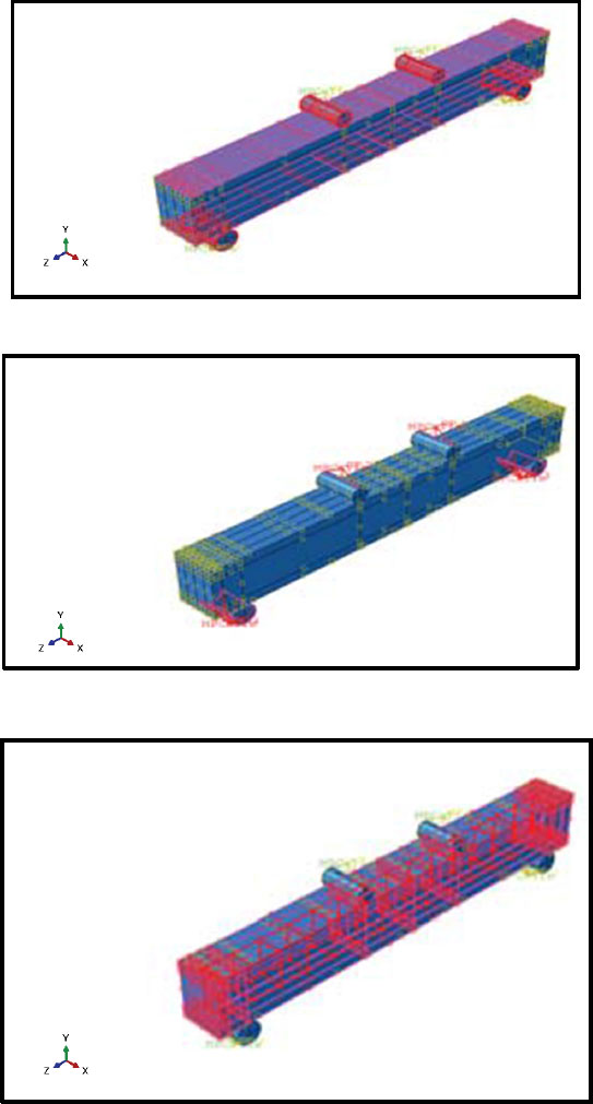
Three interaction methods were utilized in this study: surface-to-surface contact, MPC (multiple point constraint) with tie type, and embedded region. Surface-to-surface contact was implemented between the load, RC beam, and support. The load and support acted as the master surface, while the RC beam surface served as the slave. Other interaction properties were designated as “normal behavior” (pressure between surfaces) and “tangential behavior” (friction and slippage). The “hard contact” option was chosen to represent normal behaviors, and a “penalty” friction coefficient of 0.25 was set for steel-to-steel interaction. At the same time, 0.6 was applied for steel-to-concrete interaction based on friction coefficient values and prior FEA research.
Additionally, MPC constraint with tie type was applied to the load and support of the beam. This constraint defined interactions between the steel angle and the beam, ensuring load transfer and bonded conditions. The embedded method was employed for a more accurate model of reinforced concrete behavior, establishing a perfect bond between the reinforced concrete. This approach considered reinforced concrete interfaces, including slips and dowels, defining “tension stiffening” to simulate load transfer over cracks through the rebar. Results related to concrete damage plasticity, encompassing compressive crushing and tensile cracking, were derived from mechanical property experiments. Fig. (7) illustrates the interactions employed in the finite element method. This is important because Interaction modeling allows the simulation to capture the realistic behavior of components within a structure. Besides, certain types of interactions, such as contact between materials or connections, play a role in failure mechanisms. Modeling these interactions helps predict potential failure modes, such as cracks, fractures, or separations, providing insights into the structural integrity.
3.9. Boundary Conditions and Convergent
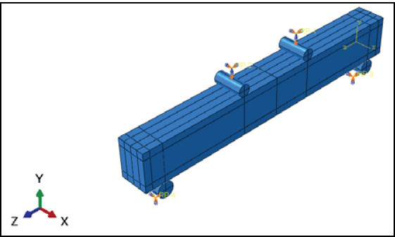
Boundary conditions were implemented on all the specimens in this study, illustrated in Fig. (8). The loads received a pinned boundary condition to restrict displacement in vertical and horizontal movements. However, rotation was permitted, and the support was designated as fixed. Displacement was gradually and smoothly applied to avoid significant changes in acceleration between increments. Additionally, the dynamic explicit approach was employed to ensure a quasi-static solution, guaranteeing smooth variations in velocity and displacement. The “smooth step” amplitude was utilized to prescribe displacement to the model.
All elements were designated dependent elements for the convergent study to facilitate the meshing of each element. Uniform mesh sizes were employed for concrete, support, and load, using three-dimensional, eight-node, reduced integration hexahedral elements with hourglassing controls (C3D8R). Three-dimensional, two-node, embedded truss elements (T3D2) represented the main reinforcement and shear link. The accuracy of the results relied on the mesh size and the total number of generated model elements. While a finer mesh yields more precise results, it can lead to numerical failure after a certain point, rendering the mesh size dependent, especially in plasticity-based models exhibiting strain softening. Hence, selecting an appropriate mesh size is crucial. Fig. (9) illustrates the load-deflection curve of beams in response to different mesh sizes. The beam with a 10 mm mesh size exhibited accurate results compared to the experimental outcomes. Therefore, it was chosen for all elements in this research. Fig. (10) presents the mesh model in the RC beams.
4. RESULTS AND DISCUSSION
4.1. Mechanical Properties of Reinforcement Bar
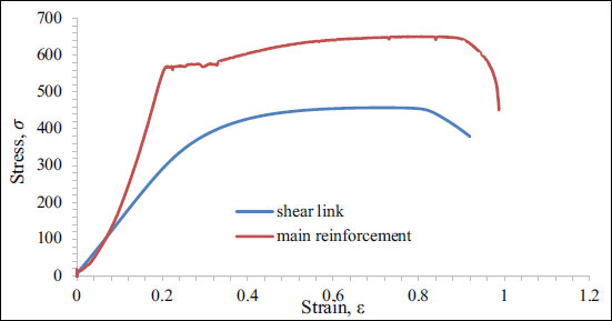
Fig. (11) illustrates the stress-strain curve of the reinforcement bars. The main reinforcement bar exhibits a yielding tensile strength of 560 MPa and an ultimate tensile strength of 640 MPa, with a modulus of elasticity of 205 GPa. In contrast, the shear link demonstrates a yielding tensile strength of 360 MPa and an ultimate tensile strength of 460 MPa, accompanied by a modulus of elasticity of 195 GPa.
| Beam Type | Initial Crack (kN) | Ultimate Load (kN) | Failure Mode |
|---|---|---|---|
| Control | 22 | 81 | Flexural and shear failure |
| Control (20% fly ash) | 20 | 80 | Flexural and shear failure |
| 100% CCBA 100% FCBA |
25 | 88 | Flexural and shear failure |
| 100% CCBA 50% FCBA |
21 | 77 | Flexural and shear failure |
| 50% CCBA 100% FCBA |
21 | 85 | Flexural and shear failure |
| 50% CCBA 50% FCBA | 20 | 78 | Flexural and shear failure |
4.2. Failure Mode and Crack Pattern on Experimental Test
Analyzing the flexural test outcomes provides insights into the failure modes and crack patterns observed in the tested reinforced concrete (RC) beams. Notably, the location and nature of cracks offer valuable information about the specimens' structural behavior and load-carrying capacity. The flexural test results reveal the initiation of small cracks near the bottom of the mid-section of the reinforced concrete (RC) beam, particularly in the region experiencing the highest bending moment.
Table 7 presents the comprehensive cracking data for all the tested specimens. Video recordings from the experimental tests indicate that the initial crack appeared at a load of 22 kN for the control beam. Similarly, for the control beam with 20% fly ash, 100% coarse coal bottom ash (CCBA), 100% fine coal bottom ash (FCBA), 100% CCBA with 50% FCBA, and 50% CCBA with 50% FCBA beams, the primary cracks emerged at loads of 20 kN, 25 kN, 21 kN, 21 kN, and 20 kN, respectively. These results highlight that the cracking initiation occurred within a consistent load range of 20 kN to 30 kN for all tested beams. The detailed assessment of crack initiation and propagation is essential for understanding the structural performance of the RC beams and shedding light on the influence of coal bottom ash substitution on crack development and overall behavior.
4.3. Comparison of Cracking Pattern Between Experimental and Simulation Analysis
All tested RC beam specimens exhibited a consistent cracking and failure mode pattern, as depicted in Fig. (12). A comparison between the experimental and simulation cracking patterns is presented in Figures A to F, revealing noteworthy similarities between the two analyses. The observed cracking behavior reflects the response of the RC beams under varying loads, shedding light on their structural integrity.
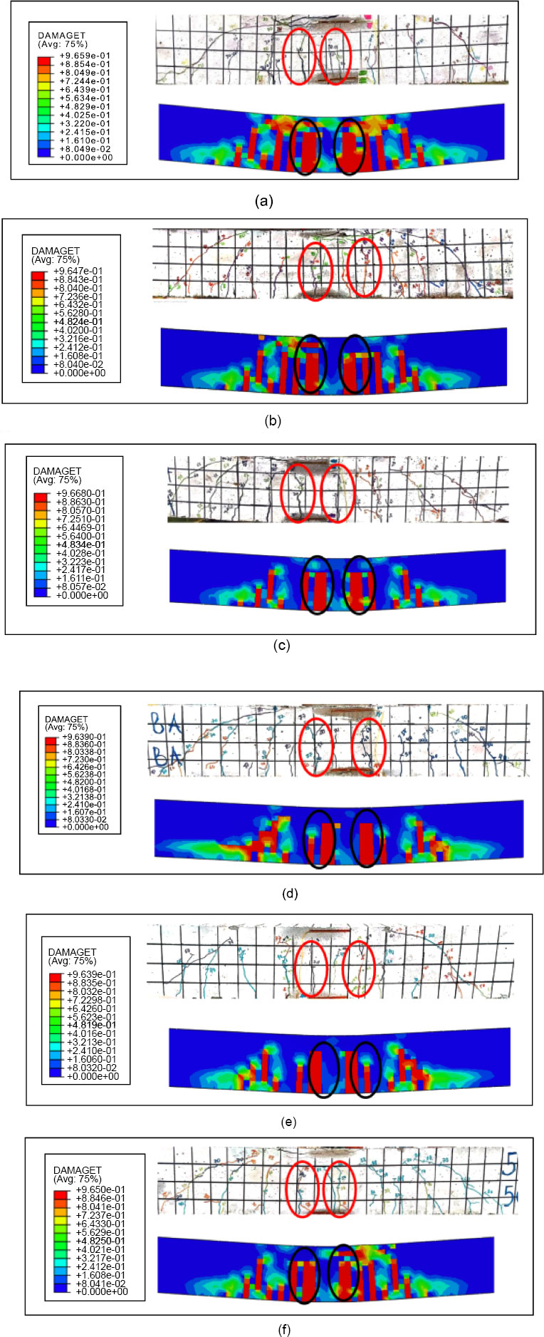
The flexural cracks primarily manifested within the pure bending zone, characterized by concrete tensile strain reaching its maximum value and inducing crack initiation. As the applied load increased, existing cracks propagated, and new ones emerged in the interstitial spaces. Concrete crushing occurred when the steel bars within the stress zone transitioned into the yielding stage, forming multiple flexural fractures. Notably, diagonal fractures emerged in the shear span, while vertical flexural cracks predominantly emerged in the mid-span region. Additionally, a subset of cracks, connected to the primary flexural cracks, developed beyond the typical bending zone. As the load intensified, the flexure fractures deepened, culminating in a combination of flexural and shear failures arising from concrete crushing.
Comparing these findings to the simulation results, it is essential to note that ABAQUS, while unable to fully simulate the propagation of hairline cracks around the beam models, effectively captured the concrete behavior under tension and compression. Despite this limitation, the FEA model closely replicated the observed cracking pattern, mirroring the experimental outcomes. These observations align with analogous studies conducted by [31-33]. These research efforts demonstrated that the FEA models accurately predicted both the cracking patterns and ultimate loads, highlighting the capability of these models to capture the nonlinear behaviors inherent to the tested materials. The congruence between the experimental and simulation cracking patterns reinforces the validity of the finite element analysis approach in replicating real-world structural responses. It provides valuable insights into the behavior of RC beams subjected to different loading conditions.
The comprehensive comparison between experimental and simulation cracking patterns enhances the credibility of the finite element analysis technique. It enriches our understanding of the intricate behaviors of RC beams under varying loading scenarios. The similarity observed in the cracking patterns is a testament to the accuracy of the FEA models in capturing the nuanced interactions between concrete, reinforcement, and applied loads. This similarity also underscores the potential of FEA as a predictive tool for assessing the complex responses of concrete structures. Furthermore, the correspondence between experimental and simulated cracking patterns suggests that the FEA models can effectively assist in exploring the performance of novel materials and design configurations. This capacity holds substantial promise for advancing concrete construction practices, especially in the context of sustainable material utilization and innovative structural solutions, as mentioned by [34, 35]. By leveraging the predictive power of FEA, engineers, and researchers can make informed decisions regarding complex systems' structural integrity and load-bearing capabilities, thus fostering more resilient and efficient designs.
In summary, comparing cracking patterns between experimental and simulation analyses is a pivotal link between theoretical models and real-world behaviors, substantiating the FEA's utility in simulating structural responses. This synergy between computational predictions and empirical observations elevates the comprehension of concrete behavior and empowers the engineering community to push the boundaries of design innovation and construction sustainability.
4.4. Differences on Load-deflection Result Between Experimental and Simulation Analysis
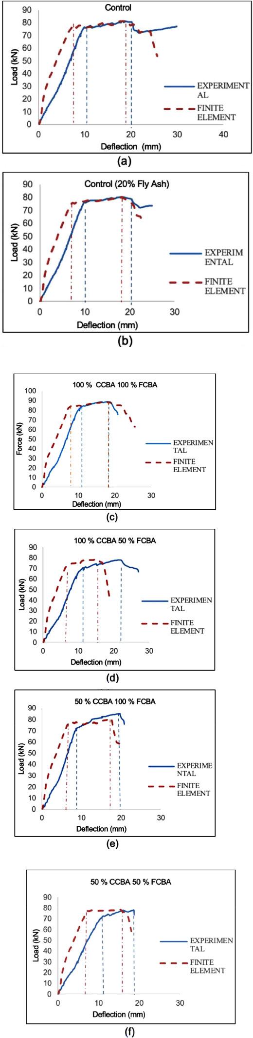
The comprehensive analysis of load-deflection behavior provides valuable insights into the structural response of the tested RC beams, both in terms of experimental observations and FEA predictions. This section not only elucidates the intricate stages of beam deformation but also highlights the congruence and disparities between the experimental and simulated results.
The load-deflection curves of the tested RC beams obtained from experimental testing and simulation using ABAQUS software are compared in Fig. (13). These curves are categorized into the elastic, plastic, and failure stages. Cracking initiates at the mid-section of the beams during the elastic stage, with minor displacements as load increases. The plastic stage is characterized by the emergence of diagonal fractures in the shear span, leading to nonlinearity in the load-deflection curve due to the development of flexural cracks. Table 8 provides load-deflection data, showing that beams with high-volume CBA as fine and coarse aggregates exhibit comparable maximum loads and maximum deflections to the control beam. Notably, the 100% CCBA and 100% FCBA specimens outperform the control beam, displaying the highest ultimate load of 88nkN and a maximum deflection of 18.87 mm.
Comparing the experimental with FEA results, there are slight differences, particularly in specimens such as 100% CCBA and 50% FCBA. Nonetheless, the FEA model closely replicates the real-world structural response. These differences can be attributed to factors like micro-cracks in experimental beams, unmodeled phenomena such as rebar concrete slip, and assumptions in the FEA model. In conclusion, the load-deflection analysis effectively bridges the gap between experimental and FEA results, offering a comprehensive understanding of the beams' behavior under different scenarios. This comparison validates the FEA's potential as a tool for simulating structural responses and guiding future design considerations. Moreover, the slight disparities underscore the complexity of real-world structural behaviors and the challenges in capturing every nuance within a computational model [36]. The differences between the experiment and the FEA model can be reduced by adjusting the model's material properties to match the experimental values. This may include parameters such as Young's Modulus, Poisson's Ratio, and yield strength. Besides, refine the mesh to ensure that it accurately represents the geometry and features of the structure. A finer mesh can provide more accurate results but might lead to numerical instability if it is too fine. Moreover, the boundary conditions can accurately be applied, reflecting the real-world constraints. This includes constraints on displacements, rotations, and other relevant degrees of freedom.
| Beams | Experimental | Finite Element Analysis | Different percentage | |||
|---|---|---|---|---|---|---|
| Max Deflection n (mm) | Max Load (kN) | Max Deflection (mm) | Max Load (kN) | Max Deflection (%) | Max Load (%) | |
| Control | 18.12 | 81 | 17.56 | 81 | 3.10 | 0 |
| Control (20% fly ash) | 18.00 | 80 | 18.20 | 80 | 0.20 | 0 |
| 100% CCBA 100% FCBA |
18.87 | 88 | 18.5 | 88 | 1.96 | 0 |
| 100% CCBA 50% FCBA |
22.29 | 77 | 15.42 | 78 | 30.82 | 1.28 |
| 50% CCBA 100% FCBA |
19.73 | 85 | 17.55 | 80 | 11.05 | 5.88 |
| 50% CCBA 50% FCBA |
18.63 | 78 | 15.42 | 78 | 17.23 | 0 |
4.5. Parametric Study
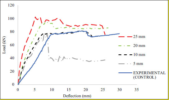
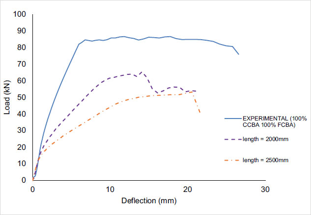
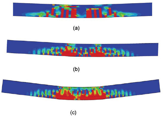
A parametric investigation was studied to explore the innovative approach performed across beams with varying lengths. Leveraging the precision of the constructed FEA model, the aim is to shed light on how different beam dimensions influence structural behavior. Fig. (14) provides a visual overview of beams of distinct lengths in terms of performance. A consistent trend emerges among the range of concrete mixture percentages: the 100% CCBA and 100% FCBA mixture consistently demonstrate superior strength performance. Thus, for simulation data, this beam with a length of 1500 mm was chosen to employ the mixture's concrete properties. The obtained results unveil intriguing findings. Beams with 2000 mm and 2500 mm lengths exhibited ultimate load capacities of 65 kN and 50 kN, respectively. What's striking is the pronounced failure occurring within the mid-section zone, as vividly depicted in Fig. (15). Analyzing the cracking patterns, this study observed that the 2500 mm beam displayed more conspicuous cracks than its 2000 mm and 1500 mm counterparts.
This study's compelling insight emerges: longer beam lengths prompt accelerated concrete failure. This observation might be rooted in the beams' insufficient original depth-to-width ratio. Furthermore, the reinforcement design appears to deviate from established design standards, suggesting an imperative need for a fresh approach in designing reinforced concrete beams to achieve enhanced structural performance. These findings resonate with the research of Rahman et al. [9], who explored similar parameters. The author's investigation into beams of differing lengths consistently revealed that longer beams are prone to more severe failures than their shorter counterparts. An amplified concentration of observable cracks accompanies this tendency. In conclusion, the parametric exploration expands the understanding of the innovative methodology applied to diverse structural scenarios. By accounting for beam dimensions, they underscore the importance of considering specific structural parameters when implementing the proposed approach.
CONCLUSION
Considering the findings presented in this study, the following key conclusions can be drawn:
1. The incorporation of 100% coarse coal bottom ash (CCBA) and 100% fine coal bottom ash (FCBA) in the concrete mix led to notable improvements in structural performance compared to the control RC beam with the ultimate load at 88 kN and maximum deflection of 18.87 mm.
2. The successful development of a finite element model using ABAQUS software for finite element analysis (FEA) demonstrates the capability of simulation tools in predicting structural behavior. The FEA results generally differ within a 10% range of experimental results.
3. The outcomes of the parametric study include a longer beam showcasing more prominent cracks and severe failure. This indicates that the parameter input in FEA was reliable and can be applied to other replacement mixtures.
4. This study underscores the proposed approach's effectiveness in enhancing the performance of RC beams. The findings validate the simulation tool's potential in predicting structural behavior and highlight the intricacies of concrete behavior under varying conditions. As future designs evolve, these insights will undoubtedly inform more accurate and robust structural assessments, paving the way for innovation and improved engineering solutions.
LIST OF ABBREVIATIONS
| CBA | = Coal Bottom Ash |
| FCBA | = Fine Coal Bottom Ash |
| CCBA | = Coarse Coal Bottom Ash |
| FA | = Fly Ash |
| FEA | = Finite Element Analysis |
| RC | = Reinforced Concrete |
| CDP | = Concrete Damaged Plasticity |
CONSENT FOR PUBLICATION
Not applicable.
AVAILABILITY OF DATA AND MATERIAL
The authors confirm that the data supporting the findings of this research are available within the article.
FUNDING
This study was funded by universiti malaysia pahang al-sultan abdullah (Awards/Grant number: RDU230301).
CONFLICT OF INTEREST
The authors declare no conflict of interest, financial or otherwise.
ACKNOWLEDGEMENTS
The support provided by Universiti Malaysia Pahang Al-Sultan Abdullah for this study is highly appreciated.

