All published articles of this journal are available on ScienceDirect.

Flexural Strength of CFSS Beams with Single and Double Web Holes

Abstract
Introduction
Web openings in structural beams facilitate building services; however, their influence on cold-formed stainless steel (CFSS) members, particularly under multiple openings, remains underexplored. This study addresses the gap in understanding of how single and double web holes affect the flexural performance and failure behavior of CFSS beams.
Methods
A total of 90 finite element models of ferritic and lean duplex CFSS beams were analyzed using ABAQUS under four-point bending. Parameters included varied cross-sections, hole diameters (20–90% of web depth), and single or double openings. Results were compared with existing design rules using reliability analysis.
Results
Web openings up to 20% of web depth showed negligible impact on flexural strength. Increasing from one to two holes caused minimal additional strength reduction, though larger openings (≥50%) led to more pronounced capacity loss. All specimens failed by flexural buckling interacting with local buckling. Existing design methods yielded conservative predictions with safety indices exceeding the recommended minimum of 2.5.
Discussion
The minimal impact of multiple openings confirms the web's limited contribution to flexural resistance under pure bending, even considering stainless steel's nonlinear behavior. Current design rules remain reliable for beams with up to two openings.
Conclusion
CFSS beams can safely accommodate single or double web openings up to 20% of web depth without significant strength loss, enabling practical service integration while maintaining structural safety.
1. INTRODUCTION
Cold-formed stainless steel (CFSS) members are increasingly used in structural engineering due to their high strength-to-weight ratio, excellent corrosion resistance, and favorable durability characteristics [1-6]. These advantages contribute to reduced maintenance and extended service life, supporting sustainable infrastructure development in line with the United Nations Sustainable Development Goals, particularly Sustainable Development Goal 9 and Sustainable Development Goal 11. However, unlike conventional carbon steel, CFSS exhibits pronounced material nonlinearity, which significantly influences buckling response, post-buckling behavior, and ultimate strength [7-9]. Among available grades, ferritic (EN 1.4003) and lean duplex (EN 1.4162) stainless steel have emerged as an efficient alternative due to their high strength, superior ductility, and cheaper market price due to a lower nickel content, particularly for EN 1.4162.
Previous studies have established a fundamental understanding of the structural behavior of cold-formed stainless steel members subjected to pure bending, particularly those fabricated from lean duplex stainless steel (LDSS) [10-12] and ferritic stainless steel (FSS) [13-15] grades. Subsequently, fewer investigations have been conducted on the structural performance of CFSS members at elevated temperature conditions [16-18]. Collectively, these investigations confirm that cold-formed stainless steel members exhibit complex interactions between local buckling, material nonlinearity, and geometric imperfections, which govern their ultimate strength.
In practical applications, web openings are frequently introduced in beam members to facilitate the integration of mechanical and electrical services. While such openings improve functional efficiency and can reduce overall structural depth, they also alter stress distribution and may trigger localized instability. Existing studies on CFSS members with web openings remain limited and are largely confined to configurations with a single opening [19-21]. Subsequently, investigations of CFSS beams with a single web opening at elevated temperatures have recently been conducted by Prabowo et al. [22] and Priestley and Prabowo [23]. The study by [22] evaluated the strength predictions of CFSS beams with a single web hole based on current design provisions, including ASCE [24], EC3 [25], and AS/NZS [26], using finite element analysis. Their results indicated that these design methods provide generally conservative and reliable predictions.
From a mechanics perspective, the assumption that the web contributes only minimally to flexural resistance suggests that multiple openings may have limited influence on bending strength. However, this assumption has not been rigorously validated for CFSS sections, where geometric slenderness and material nonlinearity may amplify local effects. Moreover, no comprehensive parametric study has been conducted that explicitly quantifies the influence of multiple web openings on the flexural behavior of CFSS beams under pure bending conditions. In addition, the reliability of existing design provisions for such configurations remains largely unexplored, particularly in terms of their ability to capture strength variations and failure mechanisms associated with multiple openings.
Addressing the current limitations on CFSS beams with multiple openings solely through experimental investigation alone is not only resource-intensive but also inherently limited in its ability to capture the wide range of geometric configurations and parameters involved. Consequently, relying solely on experimental data would result in a restricted and potentially non-generalizable understanding of the problem [27, 28]. In contrast, advanced numerical modeling offers a robust and efficient framework for systematically investigating these complex behaviors. When rigorously validated against experimental results, finite element analysis is capable of accurately capturing material nonlinearity, geometric imperfections, and local instability phenomena [29-33]. Moreover, it enables comprehensive parametric studies that are otherwise impractical to conduct experimentally [17, 33-36]. For these reasons, the use of validated numerical modelling is not only appropriate but necessary to provide a reliable and generalized assessment of the structural performance of perforated CFSS members [19, 36-38].
This study investigates the effects of single and double web holes on the pure bending strength of CFSS beams, fabricated from ferritic and lean duplex grades. The effects of the existence of multiple web holes on the strength reduction of CFSS beams under pure bending remain unexplored in existing studies [10-15, 19], while the requirement of multiple holes in the beams cannot be avoided in practice. Ultimate strengths obtained from finite element analyses conducted using ABAQUS [39] are presented to quantify the extent of strength degradation associated with multiple web openings. Furthermore, the numerical results are used to evaluate the applicability of existing design rules proposed by Chen et al. [19] and Prabowo et al. [23]. Reliability analyses are also performed to assess the safety and consistency of these design approaches when applied to beams with multiple web holes, thereby providing a more comprehensive basis for the design of perforated CFSS members.
2. RESEARCH METHOD
Numerical modelling of CFSS beams based on the study carried out by Prabowo et al. [22] was adopted for this study. Details of the numerical model, including the material modelling, finite element types, mesh sizes, and boundary conditions, can be found in [22]. The nonlinear material model used in this study was based on the laboratory test results conducted by Chen et al. [19] for the ferritic grade, and Huang and Young [40] for the lean duplex grade. Table 1 presents the extract of coupon test results, with E = Young’s modulus (MPa), f0.2 = yield strength (MPa), fu = ultimate strength (MPa), and ef = strain at failure. The strength enhancement that commonly takes place at the corner parts of the cross-section was incorporated into the model by considering the recommendation from [19]. The numerical model has been validated against the laboratory test results performed by Chen et al. [19]. Hence, results from the numerical analyses developed in ABAQUS are in close agreement with experimental results.
Upon validation of the numerical model, a parametric study was performed. The study was conducted based on numerical specimen variations, including the cross-section sizes, number of holes, and hole diameter. The typical cross-section of CFSS beams considered in the parametric study is depicted in Fig. (1), with the variations included in this study presented in Table 2, in which H = overall depth, B = overall width, t = thickness, ro = outer radius, and ri = inner radius of the corner. The hole diameter is expressed as a percentage of the flat depth (H-2t-2ri) of the web. In this study, the web hole diameters relative to the flat depth consist of 20% (D20), 50% (D50), 70% (D70), and 90% (D90).
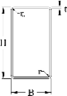
Cross-section CFLDRHS.
| H (mm) | B (mm) | t (mm) | ro (mm) | ri (mm) | (H–2(ri+t))/t | H/B |
|---|---|---|---|---|---|---|
| 80 | 60 | 4.0 | 8.0 | 4.0 | 16 | 1.3 |
| 100 | 40 | 2.0 | 4.0 | 2.0 | 46 | 2.5 |
| 100 | 100 | 3 | 6 | 3 | 29.3 | 1.0 |
| 150 | 75 | 1.5 | 3 | 1.5 | 96 | 2.0 |
| 200 | 200 | 2.5 | 5 | 2.5 | 76 | 1.0 |
The positions of web holes are located in the moment region to ensure the failure occurs exclusively within this region. The moment is denoted as L2 in Figs. (2 and 3), while L1 in the figure is defined for the shear span. The distinction between moment span and shear span is necessary for the four-point loading simulation to obtain pure bending strength in the moment. The loading point is located at one- and two-thirds of the midspan, represented by the presence of stiffener plates. This is consistent with the experimental setup of Chen et al. [19]. The stiffener plates at the ends of the beam, including those at loading points, prevented local buckling during loading assignments. The holes were located in symmetrical positions, indicated by L2A. The magnitudes of L1 and L2 are provided in Table 3. Overall, L2 ranges from 3-5 times the larger cross-section dimensions, consistent with Chen et al. [19].
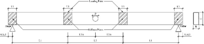
Schematic of beam with single web hole.
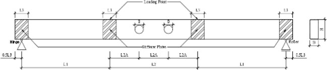
Schematic of beam with double web holes.
| H (mm) | B (mm) | L1 (mm) | L2 (mm) | L3 (mm) |
|---|---|---|---|---|
| 80 | 60 | 320 | 320 | 90 |
| 100 | 40 | 400 | 400 | 90 |
| 100 | 100 | 400 | 400 | 90 |
| 150 | 75 | 600 | 600 | 90 |
| 200 | 200 | 800 | 800 | 90 |
3. RESULT AND DISCUSSION
3.1. Flexural Strength
Two primary results obtained from ABAQUS are summarised in this section, namely ultimate flexural strengths and failure modes. Table 4 presents the ultimate flexural strength from the finite element analyses (MFEA), with MFEA, F denoting MFEA for the ferritic sections and MFEA, L for lean duplex sections. It is obvious that the MFEA, F values are smaller than MFEA, L values due to material property differences. Table 4 shows that the presence of additional web holes does not cause a substantial strength reduction. As the hole diameter increases, an additional web hole only marginally reduces the strength due to stress redistribution in the hole perimeter, owing to the inherent ductility characteristics of stainless steel material [22].
| H × B × t | % hole | MFEA, F (kNm) | MFEA, L (kNm) | ||
|---|---|---|---|---|---|
| 1 hole | 2 holes | 1 hole | 2 holes | ||
| 80 × 60 × 4 | D20 | 13.43 | 13.43 | 21.50 | 21.45 |
| D50 | 12.97 | 12.90 | 20.77 | 20.65 | |
| D70 | 12.22 | 12.16 | 19.71 | 19.57 | |
| D90 | 10.90 | 10.86 | 17.62 | 17.45 | |
| 100 × 40 × 2 | D20 | 7.54 | 7.54 | 11.46 | 11.46 |
| D50 | 6.98 | 6.96 | 10.61 | 10.61 | |
| D70 | 6.22 | 6.17 | 9.83 | 9.74 | |
| D90 | 4.94 | 5.58 | 7.68 | 8.60 | |
| 100 × 100 × 3 | D20 | 18.05 | 17.08 | 24.97 | 24.94 |
| D50 | 17.12 | 16.82 | 24.15 | 23.87 | |
| D70 | 16.69 | 16.46 | 23.52 | 22.62 | |
| D90 | 14.24 | 14.30 | 20.09 | 20.13 | |
| 150 × 75 × 1.5 | D20 | 8.29 | 8.44 | 12.18 | 12.28 |
| D50 | 7.93 | 8.02 | 12.52 | 12.63 | |
| D70 | 7.44 | 7.36 | 12.22 | 12.36 | |
| D90 | 5.98 | 5.90 | 8.98 | 9.15 | |
| 200 × 200 × 2.5 | D20 | 40.92 | 36.95 | 53.90 | 54.23 |
| D50 | 34.57 | 36.40 | 52.71 | 53.72 | |
| D70 | 31.76 | 31.91 | 41.74 | 43.35 | |
| D90 | 27.26 | 27.93 | 35.91 | 37.25 | |
Comparisons between Tables 4 and 5 show that the strength reductions due to an additional hole are relatively minimal in specimens having a 20% hole diameter. The strength reductions become more pronounced as the hole sizes increase. In theory, the bending strength is mainly derived from the top and bottom flat parts of the cross-section in Fig. (1). The bending stress is maximum at these two parts, according to the principle of mechanics. The top part experiences compression stress (fcompression), while the bottom part experiences tension stress (ftension). The force equilibrium is depicted on the right side of the figure, with C and T being the total compression and tension forces, respectively; these forces are located near the top and bottom fibers of the section. Therefore, it is understood that the presence of a web hole does not necessarily impact the strength reduction, especially when there are multiple holes in the beam web. This explanation can also be illustrated using (Fig. 4). The larger the size of H or Z (moment lever arm), the less the influence of the beam web on the bending strength.
| HxBxt | MFEA, F (kNm) | MFEA, L (kNm) |
|---|---|---|
| 80 × 60 × 4 | 13.47 | 21.56 |
| 100 × 40 × 2 | 7.55 | 11.49 |
| 100 × 100 × 3 | 18.07 | 25.02 |
| 150 × 75 × 1.5 | 8.50 | 12.35 |
| 200 × 200 × 2.5 | 41.23 | 54.69 |
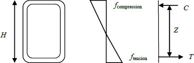
Bending stress development in the beam.
3.2. Failure Modes
The failure modes obtained from ABAQUS are shown in Figs. (5 to 7). From these three figures, it is shown that no shear failure occurred in the shear span. In addition, all figures show bending failure occurring within the moment span, which was characterized by flexural buckling combined with local buckling.
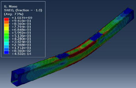
Failure mode of section 80 × 40 × 4 without hole.
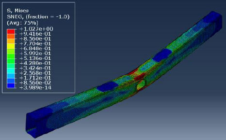
Failure mode of section 80 × 40 × 4 with 1 web hole D70.
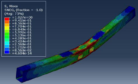
Failure mode of section 80 × 40 × 4 with 2 web holes D70.
3.3. Comparison with Strength Predictions
Three strength predictions were evaluated in this study, including those proposed by ASCE [24] (MASCE), Chen et al. [19] (MC), and Priestley and Prabowo [23] (MP). The values of MASCE, MC, and MP are obtained from Mn in Eq. (1), where Mnl is obtained from Eqs. (2 and 3), and Mynet is obtained from Eq. (4). These three strength predictions are originally applicable to beams with a single web hole. Hence, this study investigates their applicability to beams with multiple web holes. Overall, these three strength predictions have similar equation formats as follows:

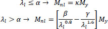


where Mn = Nominal flexural strength of the beams without and with web holes; Mynet = Flexural strength based on net section elastic modulus (Snet); Mnl = Flexural strength of section under combined local and flexural buckling mode; My = Yield moment of cross-sections (S. f0.2); Mcrl = Critical local buckling strength obtained from the CUFSM (Constrained and Unconstrained Finite Strip Method) tool; and are obtained from Table 6.
Based on Table 6, it is shown that the strength predictions prescribed by ASCE [24] are the most conservative since they do not account for the strength enhancement of a stocky section (λl ≤ α). The other two strength predictions take into account the strength enhancement, as it permits Mn > My.
It has been mentioned above that the strength predictions require the Mcrl value, which can be obtained using CUFSM software [41]. A preview of CUFSM results is shown in Fig. (8) for sections without a web hole (lean duplex 80 × 40 × 4), while sections with double web holes were treated as a single web hole (Fig. 9) due to limitations of the CUFSM and for simplification. The rationale behind this simplification is that the bending stress along the moment span will be uniform under four-point loading.
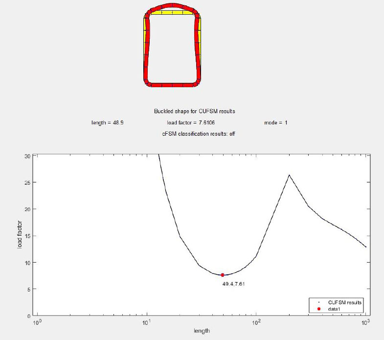
CUFSM preview results for sections without a web hole.
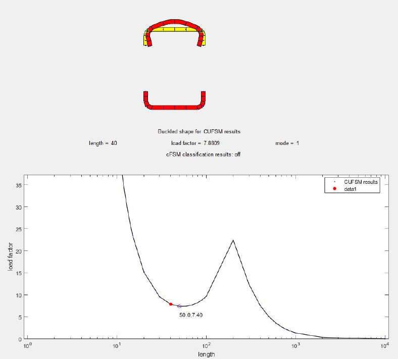
CUFSM preview results for sections with a web hole.
From Figs. (8 and 9), the values of Mcrl are shown at the lowest point of the curve, where indicated by a red dot. The first numbers (49.4 and 50.0) indicate the half-wave buckling length, while the second numbers (7.61 and 7.40) indicate the Mcrl values. These values were then multiplied by My as an input to Eqs. (2 and 3). For sections with the web holes, the Mcrl values obtained from CUFSM must be compared with Mcrl values associated with the hole diameter read from the curve. More details regarding the determination of Mcrl for sections with a web hole can be found in the study by Prabowo et al. [22]. In summary, the Mcrl shall be obtained from the following considerations:
- If the hole diameter < half-wave buckling length obtained from the CUFSM calculation for sections with holes (like Fig. 9), then Mcrl equals the corresponding CUFSM calculation for sections without holes,
- Otherwise, the Mcrl shall be taken from the CUFSM calculation for sections with holes.
- It should be noted that the Mcrl value for sections with holes should not exceed the Mcrl of sections without holes.
Evaluations of the three strength predictions were performed using the reliability analysis formula provided by ASCE [24], using the applicable load combination of 1.2 Dead Loads plus 1.6 Live Loads. Results from the comparison between MFEA with MASCE, MC, and MP are summarised in Table 7. The purpose of this comparison is to demonstrate how conservative the three strength predictions are for the 90 variations that are used in this study. Moreover, the safety index (βo) of the three strength predictions is obtained by using the reliability analysis. The magnitude of (βo) is obtained from Chapter 11 of ASCE [24], which is primarily governed by the mean of the ratio between MFEA and Mn (calculated from the three strength predictions) and the coefficient of variation (COV) of the ratio between MFEA and Mn. A minimum (βo) value of 2.5 must be achieved to determine that the strength prediction can be used safely.
| Grades | Ferritic | Lean Duplex | ||||
|---|---|---|---|---|---|---|
| Mn = MASCE | Mn = MC | Mn = MP | Mn = MASCE | Mn = MC | Mn = MP | |
| Mean (MFEA/Mn) | 1,22 | 1,20 | 1,43 | 1,25 | 1,22 | 1,50 |
| COV of MFEA/Mn | 0,164 | 0,181 | 0,110 | 0,128 | 0,145 | 0,098 |
| ϕ | 0,9 | 0,9 | 0,9 | 0,9 | 0,9 | 0,9 |
| βo | 2,94 | 2,77 | 3,91 | 3,25 | 3,05 | 4,21 |
From Table 7, it is shown that the three strength predictions are conservative since the mean values are greater than 1, even though the stainless steel grades are different. The least conservative predictions were offered by Chen et al. [19], as indicated by the lowest mean value. However, the least scattered predictions were obtained from Prabowo et al. [22] strength prediction, as indicated by the smallest COV values. Moreover, when using the same strength reduction factor, the three strength predictions were found to be safely used, as the βo values were greater than 2.5. The most optimum strength prediction came from the study by Chen et al. [19], since it had the lowest βo values.
CONCLUSION
This paper presents an investigation into the flexural strength of cold-formed ferritic and lean duplex stainless steel beams under four-point loading with single and double web holes. A total of 90 numerical specimens were developed and analysed using finite element analysis. The pure bending strength was evaluated within the constant moment region, and all specimens exhibited failure governed by flexural buckling interacting with local buckling. The numerical results were used to assess the applicability of existing strength prediction methods for cold-formed stainless steel beams with web openings. The findings demonstrate that current design provisions provide conservative and safe predictions for beams with single and double web holes, as well as for beams without openings. The inclusion of single web hole cases enables a comprehensive evaluation of the design methods, and the calculated safety indices confirm the reliability of these approaches across different hole configurations.
Despite these contributions, several limitations should be acknowledged. The study is based primarily on finite element modelling, and although validated against available experimental data, the validation was limited to specific cases. The investigation is also restricted to pure bending conditions, whereas practical structures may experience combined loading effects. In addition, the parametric scope was limited to selected cross-sections and opening configurations.
Future research should therefore focus on experimental validation of beams with multiple web openings, as well as investigations under combined loading conditions and more complex opening arrangements. The development of refined design methods that explicitly consider multiple openings is also recommended to further enhance the reliability and applicability of practical design approaches.
AUTHORS’ CONTRIBUTIONS
The authors confirm their contributions to the paper as follows: A.P.: Study conception, design, analysis, interpretation of results, and manuscript editing; I.P.: Data collection, analysis, manuscript draft; D.T.W.L.: Supervision, manuscript editing. All authors reviewed the results and approved the final version of the manuscript under the heading of Author Contribution.
LIST OF ABBREVIATIONS
| CFSS | = Cold-Formed Stainless Steel |
| LDSS | = Lean Duplex Stainless Steel |
| E | = Young’s modulus |
| f0.2 | = yield strength |
| fu | = ultimate strength |
| ef | = strain at failure |
| H | = overall depth |
| B | = overall width |
| t | = thickness |
| ro | = outer radius |
| ri | = inner radius of corner |
| H-2t-2ri | = flat depth |
| L1 | = shear span (left) |
| L2 | = moment span |
| L2A | = one-third of moment span |
| L3 | = shear span (right) |
| FEA | = Finite Element Analysis |
| MFEA, F | = Ultimate strength of ferritic beams obtained from FEA |
| MFEA, L | = Ultimate strength of lean duplex beams obtained from FEA |
| fcompression | = compression stress |
| ftension | = tension stress |
| C | = compression force |
| T | = tension force |
| Z | = lever arm |
| Mn | = Nominal flexural strength of the beams without and with web holes |
| Mynet | = Flexural strength based on net section elastic modulus |
| Snet | = Net section elastic modulus |
| Mnl | = Flexural strength of section under combined local and flexural buckling mode |
| My | = Yield moment of cross-sections |
| S | = Elastic modulus |
| Mcrl | = Critical local buckling strength obtained from CUFSM |
| CUFSM | = Constrained and Unconstrained Finite Strip Method |
| COV | = Coefficient of Variation |
| ϕ | = Strength reduction factor |
| βo | = Reliability index |
FUNDING
This research is supported by the research funding provided by the university through the Institute for Research and Community Service.
ACKNOWLEDGEMENTS
The first author acknowledges the contributions of the second author, as this paper presents part of his master's thesis. Computational analysis of using ABAQUS is facilitated by Tarumanagara Foundation.