All published articles of this journal are available on ScienceDirect.

The Effect of Longitudinal Hollows on the Carbon Footprint and Economic Behavior of RC Deep Beams

Abstract
Introduction/ Objective
This study investigates the environmental and economic impact of using longitudinal hollows in RC deep beams, identifying the optimal hollow configuration based on weight reduction compared to peak load.
Methods
Sixteen deep beams were cast and tested, fifteen of which contained longitudinal hollows, along with a control beam. The deep beams were divided into five groups to study the effects of the number and depth of hollows, the geometric shape of the hollows, the diameter of the hollows, and the slope of the hollows.
Results
The results illustrated that using longitudinal hollows decreases the peak load of the beams by 2.8% to 20.1%, leads to a reduction in weight of 3.56% to 12.35%, reduces CO2 emissions by 3.82% to 13.82%, and decreases embodied energy consumption by 3.48% to 13.80%.
Discussion
Economic analysis indicates that the construction costs of the deep beams are reduced by 3.81% to 13.71% compared to the control beam. Moreover, the behavior of beams with fewer hollows was better, and the smaller hollow diameters resulted in improved peak load capacity. The deep beam with a circular hollow section performed better than other shapes, especially when centered and without a slope, as a slope reduces its peak load capacity.
The construction cost of the deep beams is reduced by 3.81% to 13.71% compared to the control beam. Moreover, the behavior of beams with fewer hollows was better, and the smaller hollow diameters resulted in improved peak load capacity. The deep beam with a circular hollow section performed better than other shapes, especially when centered and without a slope, as a slope reduces its peak load capacity.
Conclusion
Using longitudinal hollows in RC deep beams presents a viable alternative for reducing environmental impact, as well as lowering the cost and waste of raw materials used in their construction, while maintaining satisfactory structural performance, especially for beams with small hollow diameters.
1. INTRODUCTION
RC (reinforced concrete) deep beams are widely used in facilities such as bridges, foundations, and RC dams. Deep beams are defined geometrically when the ratio of clear span to total depth (ln/h) is less than or equal to 4 or when the ratio of shear span to effective depth (a/d) is less than or equal to 2, which enhances their ability to withstand large loads and stresses [1-5]. Deep beams exhibit unique behavior compared to other beam types, as they are more susceptible to shear forces and shear cracking due to their lower span-to-depth ratio 2. This unique behavior requires shear design, bracing strategies, and special analysis methods such as STM [6]. For this type of beam, shear failure is the dominant mode of failure due to load transfer through strut-and-tie action [6, 7].
Recently, the use of longitudinal hollows in beams has become widespread to reduce the amount of concrete used in their construction, thereby reducing carbon dioxide emissions, energy consumption, and costs. Furthermore, these hollows can be used to pass various utilities, including plumbing, electrical, and communication lines, without significantly affecting the beam's structural behavior [8-12]. These hollows are typically constructed using recycled plastic pipes to protect the utilities passing through them from external elements. The presence of longitudinal hollows in RC deep beams differs from their presence in other types of beams, wherein, in deep beams, load transfer is governed by a strut-and-tie style, but the load is transferred through compression struts and tension ties, which is governed by the shear force and also the redistribution of stresses in it [13-15].
One of the positive economic aspects of using longitudinal hollows is their sustainability in terms of concrete consumption, especially given the increasing demand for concrete and the growth of the infrastructure construction sector [16, 17]. This has made concrete the second most consumed material after water. Therefore, using longitudinal hollows and reducing the amount of concrete used leads to the conservation of natural resources and a decrease in their consumption [18, 19]. Moreover, the use of longitudinal hollows in beams is one of the sustainable technologies, as it reduces the quantities of raw materials for concrete and thus reduces the quantities of CO2 emissions, since reducing the use of cement, as its manufacture is one of the largest processes that contribute to CO2 emissions [20-22]. Similarly, regarding energy, its manufacture consumes a large amount of energy that exceeds the production of many materials, as it is the third most energy-consuming material after aluminum and steel [23], and the production of one ton of cement requires the consumption of 1500 units of raw materials and approximately 80 units of electricity [24].
Therefore, numerous efforts have been made to study these hollows and their impact on the structural behavior of deep beams, given that they consume larger quantities of concrete than other types of beams. Some of these studies include: Ismail et al. [25] investigated the effects of changing the geometric shape, location, and size of the longitudinal hollows on the behavior of deep beams with self-compacting RC. Al-Maliki et al. [26] numerically investigated the behavior of deep hollow beams reinforced with CFRP using ANSYS, both with single and double layers of reinforcement, and also studied the effect of changing the geometry of the longitudinal hollows when using square and circular hollows. Mahdi and Muhaysin [27] experimentally investigated the presence of steel fibers at percentages of 0.75% and 1.5% in RC deep beams and their effect on the pure torsional behavior and torsional angle of RC deep beams with longitudinal hollows. Shabanlou et al. [28] focused on the behavior of deep beams that contain transverse circular hollows in the web when exposed to fire. Delshad et al. [29] investigated the effect of hollows on the structural behavior of RC deep beams using CFRP and GFRP (polymer with glass fiber reinforced) and then evaluated the effectiveness of the reinforcement in improving the peak load of the deep beams. It is worth noting that the studies that dealt with this technique (longitudinal cavities) are limited; there is a gap in terms of studies that examine the sustainability and cost analysis of this type of beam, linking its structural behavior to its sustainable aspects and determining the optimal choice accordingly.
Therefore, to fill this gap, this study provides an economic and environmental analysis, as well as a study of the behavior related to the structural behavior and weight of these beams that contain longitudinal hollows, which allows for the optimal selection of hollows according to cost, carbon footprint, beam weight, and load-bearing capacity, which facilitates the selection of the longitudinal hollow condition in this type of beam for facilitating the passage of services through them.
2. MATERIALS AND METHODS
2.1. Beam Details
Sixteen RC deep beam specimens were prepared and tested, including fifteen with longitudinal hollows and a solid reference specimen without hollows. All of them had the same geometric dimensions: length 1400 mm, height 320 mm, and width 150 mm. All specimens also had the same reinforcement. The tension zone was reinforced by 4 Ø 12 mm to resist tensile stresses on the bottom, and shear reinforcement was provided by stirrups Ø 4 @ 56 mm c/c and Ø 4 @ 57 mm c/c for skin reinforcement, as shown in Fig. (1). The beams were divided into five groups based on the following variables: number of hollows in each beam, diameter of the hollows, location of the hollows relative to the beam cross-section, geometric shape of the longitudinal hollows, and slope of the longitudinal hollows, as illustrated in Table 1 and Fig. 2a-e, respectively.
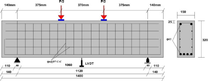
Deep beam setup and reinforcement arrangement (in mm).
| Groups | Type of Variable | Designation of Deep Beam | Description |
|---|---|---|---|
| - | - | Ref. | Reference deep beam |
| 1 | Hollows number | DBN1 | Single longitudinal hollow with a constant diameter of 50 mm |
| DBN2 | Double longitudinal hollows with a constant diameter of 50 mm | ||
| DBN3 | tripartite longitudinal hollows with a constant diameter of 50 mm | ||
| 2 | Hollows diameter | DBD25 | tripartite longitudinal hollows with a constant diameter of 25 mm |
| DBD32 | tripartite longitudinal hollows with a constant diameter of 32 mm | ||
| DBD50 | Tripartite longitudinal hollows with a constant diameter of 50 mm | ||
| 3 | Hollows position | DBP76 | The center of the hollow is 76 mm from the bottom face. |
| DBP138 | The center of the hollow is 138 mm from the bottom face. | ||
| DBP200 | The center of the hollow is 200 mm from the bottom face. | ||
| 4 | Hollows geometry | CIR50 | Circular hollow |
| RHO47x47 | Rhombic hollow | ||
| REC65x35 | Rectangular hollow | ||
| 5 | Hollows slope | HDB0 | Hollow deep beam with 0% slope. |
| HDB4.3 | Hollow deep beam with 4.3% slope. | ||
| HDB7.85 | Hollow deep beam with 7.85% slope. |
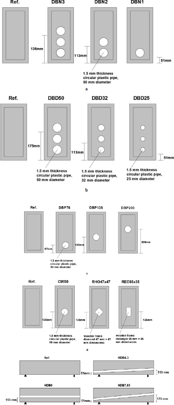
Deep beam sections with hollows: (a) group (one): hollows number; (b) group (two): hollows diameter; (c) group (three): hollows location (position) (d) group (four): hollows geometry; (e) group (five): hollows slope.
2.2. Materials of Deep Beams
2.2.1. Concrete Components
All specimens were cast using normal concrete made with Portland cement Type 1 according to ASTM C150 [30]. Gravel with a maximum sieve size of 10 mm was used, which meets the requirements of ASTM C33 [31]. The mix design complied with the recommendations of the ACI [32] mix design method. Table 2 shows the proportions of concrete mix components used.
|
Cement (kg/m3) |
Sand (kg/m3) |
Crushed Gravel (kg/m3) |
Water (kg/m3) |
Compressive Strength f'c MPa (28 days) |
|---|---|---|---|---|
| 400 | 750 | 780 | 240 | 27.5 |
2.2.2. Steel Reinforcement
During this study, bars with a diameter of 12 mm and a yield value of 620 MPa were used to strengthen the tensile and compression zones. For the horizontal and vertical shear reinforcement, 4 mm diameter bars were used with a yield value of 430 MPa, according to ASTM A615 [33].
2.3. Economic Framework for Raw Materials
To assess the economic feasibility of hollow RC deep beams, cost savings were calculated using local market unit prices for raw materials, as detailed in Table 3. It is worth noting that only the raw materials for the concrete were calculated, as this is the only factor whose quantity will change when using longitudinal hollows. All specimens have the same reinforcing steel and other details. Therefore, the cost will be calculated only for the concrete materials (gravel, sand, and cement). Prices for recycled PVC pipes were excluded because they are extracted and reused for other purposes.
| Material | Price in $/m3 |
|---|---|
| Sand | 24 |
| Gravel | 20 |
| Cement | 130 |
| Plastic pipes | 200 |
3. RESULTS
The results present a comprehensive, integrated evaluation of experimental and analytical outputs, based on a methodology that balances structural performance with environmental sustainability considerations. The findings are defined across three key tracks: the first focuses on structural behavior, specifically the load-bearing capacity of the beams; the second focuses on the environmental and economic performance of these hollow deep beams, including CO2 emissions, embodied energy, self-weight reduction, and economic considerations; and the third focuses on determining the optimal hollowness that aligns with both structural and environmental performance.
3.1. Critical Loads
As exhibited in Fig. (3), shear failure is the predominant failure in all RC deep beam specimens containing longitudinal hollows and the reference specimen. Table 4 and Fig. 4a (series one), 4b (series two), 4c (series three), 4d (series four), and 4e (series five) show the effect of the presence of longitudinal hollows on the peak load of deep beams, where it is perceived that the peak load of RC deep beams with hollows decreased with an increase in the number of hollows from one and two hollows to three hollows by 8.12%, 17.08%, and 20.1%, respectively, when compared to the reference specimen. For a single hollow, the effect depends on its distance from the tension zone; at 76 mm, 138 mm, and 200 mm, the decreases are 8.12%, 6.72%, and 13.17%, respectively. The shape of the longitudinal hollows also significantly affects peak load: when a single longitudinal hollow is circular, rhombic, or rectangular, the corresponding reductions are 7.56%, 11.72%, and 6.16%, respectively, relative to the reference specimen. However, when changing the diameter of the single longitudinal hollow, the decrease increases with the increasing diameter by 2.80%, 7.56%, and 20.1% for diameters of 25 mm, 32 mm, and 50 mm, respectively. Finally, the slope of the longitudinal hollows has an inverse effect: as the slope increases from 0% to 4.3% and then to 7.85%, the load decreases, reducing the peak load of the beams by 7.56%, 8.96%, and 11.2%, respectively, compared to the reference specimen.
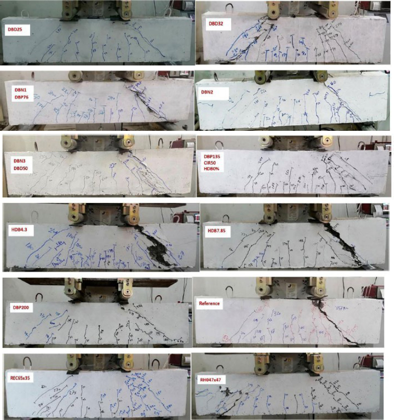
Failure pattern in deep beams (with and without longitudinal hollow).
|
Beam Code |
Lowering in vol. of Beams [%] |
Peak Load [kN] |
Lowering in Pu [%] | Lowering in CO2 Emission (kg) | Lowering Embodied energy |
Lowering in Weight (kg) |
Lowering in Cost ($) |
|---|---|---|---|---|---|---|---|
| Reference | - | 357 | - | 0 | 0 | 0 | 0 |
| DBN1 | 4.1 | 328 | 8.12 | 4.62 | 4.59 | 4.11 | 4.58 |
| DBN2 | 8.2 | 296 | 17.08 | 9.19 | 9.19 | 8.58 | 9.14 |
| DBN3 | 12.3 | 285 | 20.1 | 13.82 | 13.80 | 12.35 | 13.80 |
| DBP76 | 4.1 | 328 | 8.12 | 4.62 | 4.59 | 4.11 | 4.58 |
| DBP138 | 4.1 | 333 | 6.72 | 4.62 | 4.59 | 4.11 | 4.58 |
| DBP200 | 4.1 | 310 | 13.17 | 4.62 | 4.59 | 4.11 | 4.58 |
| RHO47*47 | 4.1 | 330 | 7.56 | 4.62 | 4.59 | 4.11 | 4.58 |
| REC65*35 | 4.1 | 315 | 11.72 | 4.62 | 4.59 | 4.11 | 4.58 |
| CIR50 | 4.1 | 335 | 6.16 | 4.62 | 4.59 | 4.11 | 4.58 |
| DBD25 | 5.03 | 347 | 2.80 | 3.82 | 3.48 | 3.56 | 3.81 |
| DBD32 | 6.15 | 330 | 7.56 | 6 | 5.98 | 5.4 | 5.98 |
| DBD50 | 12.3 | 285 | 20.1 | 13.82 | 13.80 | 12.35 | 13.71 |
| HDB0%S | 4.1 | 330 | 7.56 | 4.62 | 4.59 | 4.11 | 4.58 |
| HDB4.3%S | 4.1 | 325 | 8.96 | 4.62 | 4.59 | 4.11 | 4.58 |
| HDB7.85%S | 4.1 | 317 | 11.2 | 4.62 | 4.59 | 4.11 | 4.58 |
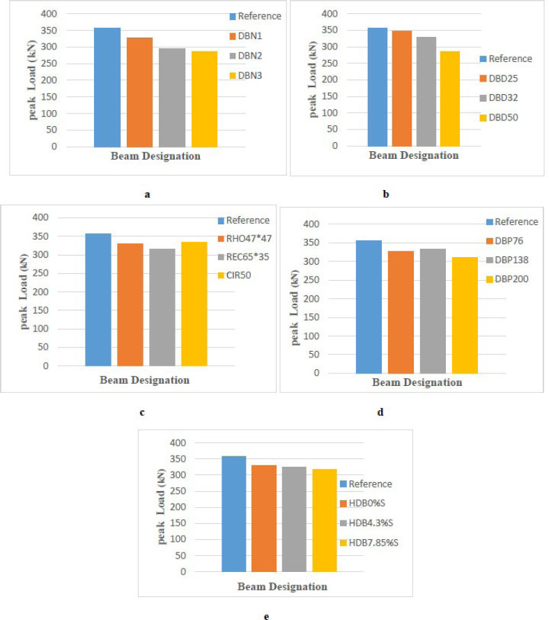
Effect of longitudinal hollows on the peak load: (a) series one, (b) series two, (c) series three, (d) series four, and (e) series five.
It is worth noting that in all five cases, as exhibited in Fig. (5), the peak load of the deep hollow concrete beams remained higher than the theoretical peak load calculated using the structure and design criteria for deep beams, using Strut and Tie modeling according to the latest American code updates [34]. As exhibited in Fig. (6).
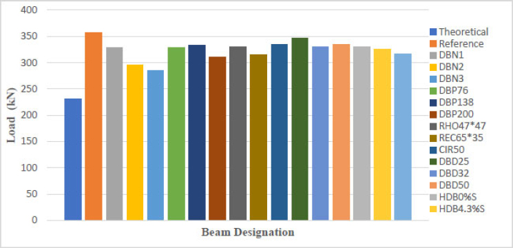
The peak load of each hollow deep beam compared to the reference specimen and the calculated theoretical load.
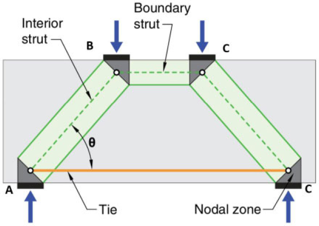
Description of strut and tie model [33].
According to the support and ligament model [34], the nominal load can be calculated (Eq. 1):
The theoretical load of the deep beam (Eq. 2):
3.2. Sustainability Benefits
The presence of longitudinal hollows in deep RC beams provides multiple sustainable and structural benefits that serve the interests of the structural element in particular and the structure in general. These include reducing CO2 emissions and embodied energy, which can be calculated using the ALCORN factors [35, 36] in Table 5. Additionally, the estimated reduction in deep beam weight and the savings in construction costs can be estimated.
| Criterion | Materials | ||
|---|---|---|---|
| Sand | Gravel | Cement | |
| Embodied energy (MJ/kg) | 0.1 | 0.04 | 6.2 |
| CO2 emission (kg/kg) | 0.007 | 0.002 | 0.994 |
3.2.1. Weight Reduction
One of the most important advantages of deep beams with hollows is weight reduction, which in turn reduces the dead load of the structure and consequently the loads exerted on the foundations compared to beams without hollows. In this study, a weight reduction was observed in deep beams when using different numbers of longitudinal hollows: one, two, and three. The weight reductions were 4.11%, 8.58%, and 12.35%, respectively. Changing the depth and geometry of the longitudinal hollows also contributed to a weight reduction of 4.11%. Furthermore, varying the diameter of the hollows resulted in weight reductions of 3.56%, 5.4%, and 13.71% for three diameters: 25 mm, 32 mm, and 50 mm, respectively. Finally, the slope of the longitudinal hollow leads to a reduction in weight of 4.11%, as exhibited in Table 4.
3.2.2. CO2 Emission Reduction
CO2 emissions are a major global concern, and the use of longitudinal hollows is a proposed solution to mitigate emissions by reducing the amount of concrete used relative to beams without hollows. A decrease in carbon dioxide emissions was observed with one, two, and three longitudinal hollows by 4.62%, 9.19%, and 13.82%, respectively. Changing the depth of the hollows and the shape of the longitudinal hollow also reduced emissions by 4.62%. Changing the diameter of the hollows reduced emissions by 2.80%, 6%, and 13.82% for three hollows of 25 mm, 32 mm, and 50 mm, respectively. The slope of the longitudinal hollow also reduced emissions by 4.62%, as exhibited in Table 4.
3.2.3. Embodied Energy Reduction
The Embodied energy in concrete is significantly consumed due to the extraction and manufacturing processes of cement. Therefore, one of the advantages of using longitudinal hollows is the reduction of this Embodied energy compared to beams without hollows. Embodied energy reductions are observed when using one, two, and three longitudinal hollows at 4.59%, 9.19%, and 13.80%, respectively. Changing the depth of the hollows also reduces embodied energy by 4.69%, as does changing the shape of the longitudinal hollow. Using hollows of different diameters reduces Embodied energy by 3.48%, 5.98%, and 13.80% when using three hollows, with the first being 25 mm, then 32 mm, and then 50mm, respectively. The slope of the longitudinal hollow also has the same effect on energy reduction, at 4.11%, as exhibited in Table 4.
3.2.4. Cost Savings
Reducing the energy and weight of deep beams with hollows can lower the overall cost of constructing this structural member. The amount of cost savings depends on the volume of concrete removed in the deep beam. Cost savings of 4.58%, 9.14%, and 13.80% were observed when using one, two, and three longitudinal hollows, respectively. Costs were reduced by 4.58% when the depth of the hollows varied, and the same applied to changes in the shape of the longitudinal hollow. The cost savings were 3.81%, 5.98%, and 13.71% using three hollows, with the first being 25 mm, then 32 mm, and then 50 mm, respectively. The cost savings for beams with a slope in the longitudinal hollow were 4.58%, as exhibited in Table 4.
3.3. Optimization of Hollow Core Parameters in RC Deep Beams
There are multiple cases in choosing the nature of longitudinal holes, and it is important to identify the optimal choice for them and apply it. The number of longitudinal hollows should be minimized as much as possible, since the behavior of a single hollow is significantly better than having two or three, as exhibited in Fig. (7a). As for the optimal location of this hollow, it is best placed in the center of the RC deep beam, where the deep beam behavior is better than placing the hollow in the tension or compression zone, as exhibited in Fig. (7b). If it is necessary to make a single longitudinal hollow, it should be circular in shape because it gives better behavior than other shapes (rectangular and rhombus) in terms of decreased peak load capacity compared to the same volume of concrete produced by each hollow shape, as exhibited in Fig. (7c). Meanwhile, if it is necessary to pass three different types of services in the deep beams, it is preferable to use three hollows with a diameter of 25 mm, as the reduction in peak load is less, and a reasonable amount of concrete volume is subtracted, with the possibility of passing the largest number of services, as exhibited in Fig. (7d). In some applications, longitudinal hollows need to be sloped. Therefore, it is recommended to minimize the slope of the hollows as much as possible, since the peak load of the deep beam is inversely proportional to the slope of the longitudinal hollows, as indicated in Fig. (7e).
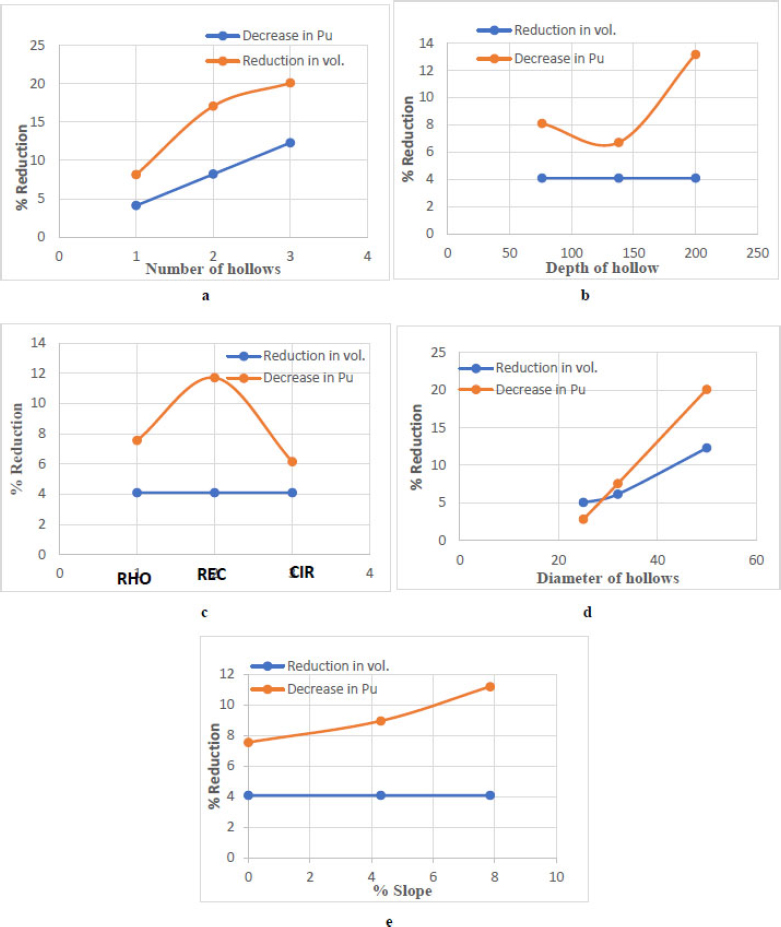
Drop in peak load and concrete volume with various longitudinal hollow cases: (a) group one, (b) group two, (c) group three, (d) group four, and (e) group five.
4. DISCUSSION
The results highlight the environmental benefits of using longitudinal hollows in RC deep beams for reducing CO2 emissions, a global challenge of our time. Emissions can be significantly reduced, as can embodied energy. Furthermore, it conserves natural resources, preventing waste and depletion, thus lowering construction costs. Regarding the beam's self-weight and peak load, the self-weight decreases with increasing hollow diameter, and the peak load is inversely proportional to the hollow diameter, as it reduces the path of the stress toward the support area, which forces the stress diversion around the hollows. The inclusion of longitudinal gaps in deep beams causes a redistribution of the stress field and generates localized plasticity zones around the cavities. This multiaxial compound stress condition explains the reduction in efficiency and load-bearing capacity of concrete struts, based on the micro-mechanical yielding criteria of materials with gaps under plastic flow. In addition to decreasing its stiffness. It is worth noting that the effect on peak load capacity is minimal until the hollow width reaches one-third of the beam width, at which point the reduction becomes somewhat significant. However, it remains within the limit, which is higher than the beam peak load capacity analyzed using STM.
5. LIMITATIONS OF THE STUDY
Although the study included 15 specimens of RC hollow-core deep beams with a solid specimen, there was no duplication of the same variable within a single example to obtain the standard deviation or variance of the result.
To mitigate this, all deep concrete beams were prepared using the same type of concrete, under the same conditions, and with the same compressive strength (27.5 MPa). Furthermore, a 28-day curing period was observed for all specimens, using the same conditions and methods. This enhanced the identification of the primary variable in each of the fifteen beams containing voids, without being affected by extraneous factors that might influence the accuracy of the variables studied in this paper.
Nevertheless, it is recommended to create a numerical representation of the studied examples to demonstrate the accuracy of the impact of the variables addressed in this paper, in addition to investigating other variables.
CONCLUSION
In general, reducing the quantity of concrete lowers the shear strength of RC deep beams, as the concrete contributes to resisting shear forces due to reduced interlocking aggregate. The following are the most important conclusions regarding beam strength and sustainability from the presence of longitudinal hollows in deep RC beams:
(1) There is an inverse relationship between the presence of hollows in RC deep beams and their ultimate load capacity. As the number of longitudinal hollows increases from one to three, the load capacity decreases from 8.12% to 20.1% due to a reduction in beam stiffness. Similarly, increasing the diameter of the hollows from 25 mm to 50 mm reduces the ultimate load capacity by 2.80% to 20.1%, as this increase in diameter decreases the beam's ability to transfer loads from the load-bearing zone to the support zone.
(2) Circular hollow performs better than rectangular and rhomboidal ones because circular shapes are more efficient at distributing stresses and preventing their concentration around the beam itself, as they lack edges and corners.
(3) The optimal location for a hollow is in the center of the beam, away from the load-bearing region, the support region, and the area of maximum tensile and compressive stress. The inclined action in the longitudinal hollows increases the obstruction of the path of the support and connection by which the beams transfer the load, thus significantly reducing the beam's peak load.
(4) Deep beams with longitudinal hollows offer excellent sustainable performance, reducing CO2 by 3.82% to 13.82% compared to the reference specimen. Using less concrete reduces the amount of raw materials used in construction, thus lowering manufacturing emissions.
(5) Deep beams with longitudinal hollows have the characteristic of providing embodied energy savings of 3.48% to 13.82% compared to the energy consumed by the reference specimen, since beams with hollows reduce the consumption of raw materials and thus reduce the energy required for these materials.
(6) Reducing the use of raw materials has an economic impact, as it leads to a decrease in the construction cost of deep beams with hollows by 3.81% to 13.80% compared to the construction cost of a reference deep beam (without hollows).
(7) Furthermore, removing the amount of concrete from deep beams significantly reduces the beam's weight by percentages ranging from 3.56% to 13.80%, which in turn reduces the beam's dead load.
AUTHOR'S CONTRIBUTIONS
The authors confirm their contributions to the paper as follows: A.H.A.: Conducted the material preparation, performed the experiments, and collected the data; M.A.I.: Developed the research concept, designed the study; and A.D.M.: Analyzed the data. All authors approved the final version of the manuscript.
LIST OF ABBREVIATIONS
| STM | = Strut and Tie Method |
| DB | = Deep Beam |
| P | = Position of hollow |
| D | = Diameter of hollow |
| N | = Number of hollows |
| S | = Slope of hollow |
| CIR50 | = Circular hollow with a diameter of 50mm |
| RHO47x47 | = Rhombic hollow with dimensions 47 mm x 47 mm |
| REC65x35 | = Rectangular hollow with dimensions 65 mm x 35 mm |
| Pn | = Nominal shear strength in kN |
| weff | = Effective width of strut in mm |
| b | = Width of deep beam in mm |
| fce | = Effective compressive strength of the concrete in a strut or a nodal zone in MPa |
| θ | = Angle of inclination of failure plane and diagonal compressive stress with the beam longitudinal axis, deg |
AVAILABILITY OF DATA AND MATERIAL
All data supporting the findings of this study are included within the article.
ACKNOWLEDGEMENTS
The authors would like to express their gratitude and appreciation to the laboratories and technical staff of the Diyala University Civil Engineering Department for providing the necessary facilities, equipment, and technical support to accomplish the experimental work of this research.