All published articles of this journal are available on ScienceDirect.
Numerical Optimization Design of Anchoring End of Prestressed Cable at Some Hydropower Station
Abstract
The paper discusses the numerical optimization design of anchoring end of prestressed cable at some hydropower station. There are two types of designing for the anchoring end, namely using square thick steel anchor bearing plate or using the round-tower anchor bearing plate. By the numerical calculation, the anchoring end using the round-tower anchor bearing plate can match the space and mechanical characteristics of the anchoring end, and stress of the anchoring end is more reasonable.
1. INTRODUCTION
Some hydropower station is the ninth hydropower station located at Wujiang river. Installed capacity of the hydropower station is 1120 MW, and the hydropower station is mainly composed of roller-compacted concrete gravity dam, overflow dam, powerhouse, and ship lift.
Overflow dam has seven overflow surface outlets, and eight gate piers. Arc door is designed for working gate, and flat gate for repairing gate. Water retaining width of arc door is 15 m, water retaining height is 24 m. The water load acting on the arc door is large, the maximum hinged thrust is 29719.9 kN when the arc door is opened. So the conventional steel arrangement cannot meet the requirement of bearing capacity and crack resistance of the gate pier concrete. Prestressed anchor cable is adopted for the gate piers [1, 2].
Preliminary design of anchor cable’s anchoring end is shown in Fig. (1). The anchoring end is composed of working anchoring plate, square thick steel anchor bearing plate and screw steel, etc [3-5]. The designing scheme is safe and conservative in the construction of hydropower station, but there exist the disadvantages. The main disadvantage is that anchor bearing plate cannot be well-consistent with the the space and mechanical characteristics of the anchoring, for its flat structure [6-11]. The stress at the center hole of the anchor bearing plate is too big after loading. The material near the orifice is in yield state. But the stress around anchor bearing plate is small, far from the yield state.
In order to solve the above problem, the round-tower anchor bearing plate is considered to be used, which is shown in Fig. (2). The anchoring end is composed of working anchoring plate, round-tower anchor bearing plate and screw steel, etc. The paper discusses the stress states of the two achoring ends.
2. MODEL FOR ANCHORING END
When using ANSYS to calculate, the anchor bearing plate, screw steel, and the near concrete shall be modeled together using three-dimensional body element. The anchor bearing plate and screw steel are modeled according to the actual size. The concrete is modeled according to minimum bearing surface of 710 mm× 710 mm of C40 concrete. Due to the structure’s symmetry, 1/8 model is calculated, which is shown in Fig. (3) and Fig. (4).
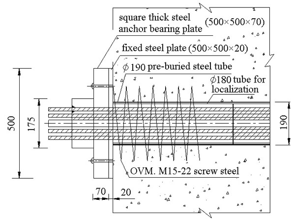
Achoring end with the square thick steel anchor bearing plate.
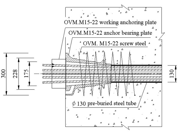
Achoring end with the round-tower anchor bearing plate.
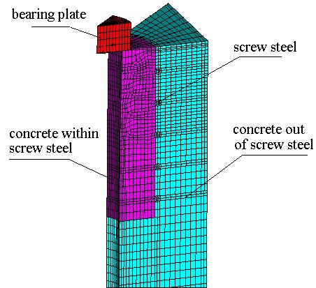
Model of finite element for square anchor bearing plate.
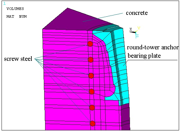
Model of finite element for round-tower anchorbearing plate.
2.1. Load and Boundary Conditions
The anchor cable with the design load of 3600 kN is adopted for the case, and 22 prestressed steel strands with the diameter of 15.24 mm are chosen. The standard tensile strength of single steel strand is 260.7 kN. Maximum load of practical engineering application is applied on the bearing plate, namely 75 % of the standard strength of steel strands (260.7×22×0.75=4301.55 kN).
Symmetry constraint is applied on the symmetry plane, and supporting constraint is applied on concrete bottom. Friction constraint is applied between anchor plate and concrete, with the friction coefficient of 0.6. Nodes of screw steel and concrete are coincident, and they are calculated as a whole.
2.2. Material Parameter
The material of anchor bearing plate is grey cast iron HT200, elastic modulus E of 120 GPa, and Poisson's ratio μ=0.3. The concrete is C40, elastic modulus E of 32.5 GPa, and Poisson's ratio μ=0.2. Screw steel is Q235, elastic modulus E of 190 GPa, and Poisson's ratio μ=0.3.
2.3. Computation Result
2.3.1 . Stress Calculation of Square Anchor Bearing Plate
Computation results are :
Fig. (5) shows that the maximum tension stress of square anchor bearing plate is 250 MPa, mainly locating at the red area of the strengthening rib, and the maximum tension stress exceeds the tensile strength of the material HT200, 200 MPa. Stress concentration will occur, for sharp corner at the corner. So the area is the weak part of the anchor bearing plate.
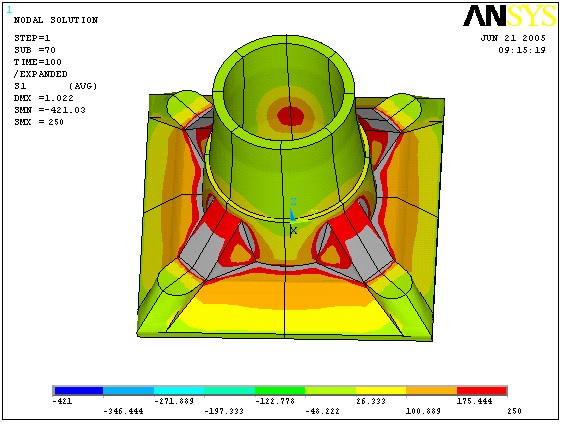
Stress diagram of square anchor Bearing Plate.
Fig. (6) shows that the stress of the first circle screw steel is maximal, 102.974 MPa. The fifth circle screw steel is minimal, 39.088 MPa. Stress difference of the circles is large.
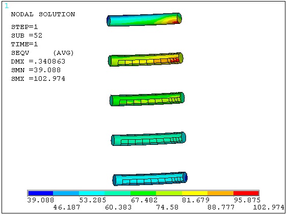
Stress diagram of screw steel when using square anchor bearing plate.
2.3.2 . Stress Calculation of Round-Tower Anchor Bearing Plate
Fig. (7) shows that the maximum tension stress of round-tower anchor bearing plate is 125.65 MPa, mainly located at the first bearing step of the bearing plate. The tension stress is less than that of the material strength of 200 MPa.
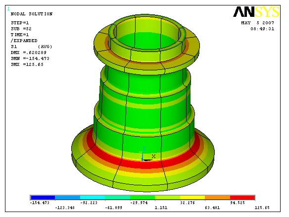
Stress diagram of round-tower anchor bearing plate.
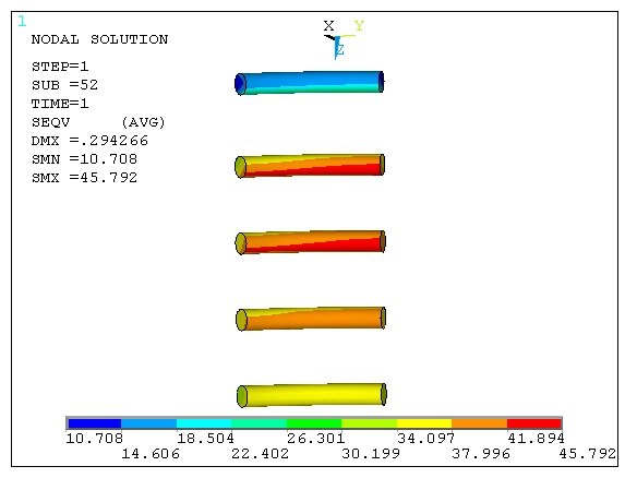
Stress diagram of screw steel when using round-tower anchor bearing plate.
Fig. (8) shows that the stress of the second and third circles of screw steels are maximal, only 45.792 MPa. The first circle screw steel is minimal, 10.708 MPa. Stress difference of the circles is little. Stresses are relatively uniform, and are far less than that of the material strength. So the screw steels are safe.
CONCLUSION
From above analysis, the following conclusions are drawn:
- The maximum tensile stress of the anchoring end was 125.65 MPa when using round-tower anchor bearing plate, far less than that when using square anchor bearing plate, 250 MPa, and also less than that of the material strength of 200 MPa.
- Stress difference of the circles was bigger when using square anchor bearing plate, the maximum of 102.974 MPa and the minimum of 39.088 MPa. While stress difference of the circles was little when using round-tower anchor bearing plate, the maximum of 45.792 MPa and the minimum of 10.708 MPa.
- So the anchoring end using round-tower anchor bearing plate could match the space and mechanical characteristics of the anchoring end, and could make full use of the performance of the material, and can make full use of the performance of the material.
CONFLICT OF INTEREST
The authors confirm that this article content has no conflict of interest.
ACKNOWLEDGEMENTS
The work is supported by the Scientific and Technological Research Program of Chongqing Municipal Education Commission (Grant No.KJ1401018), the National Natural Science Foundation of China (Grant No.51309262), Open fund of National Engineering Technology Research Center for Inland Waterway Regulation and Key Laboratory of Hydraulic and Waterway Engineering of the Ministry of Education of Chongqing Jiaotong University (Grant No.SLK2013B02), Talents Project of Chongqing Three Gorges University (Grant No.14RC03), and Science and Technology Plan Projects of Wanzhou District of Chongqing (Grant No. 201403065).


