All published articles of this journal are available on ScienceDirect.
Effect of Coating Thickness on Bond Behaviors of Polymer Cement Coated Plain Steel Bar with Concrete and Finite Element Modeling
Abstract
The pullout tests were carried out to investigate the effect of coating thickness on bond behavior (failure modes, bond strength, bond stress slip curves) between hot rolled plain steel bar (HPB) coated with polymer cement based coating and concrete. The results indicated the failure mode of the specimens is pullout. Suitable coating thickness could enhance the bond strength of steel bar embedded with concrete. By using contact surfaces with cohesive behavior in finite element software, the slip between coated plain steel bar and concrete can be realized. The results of numerical simulation are close to that of experiments, indicating that the model using contact surfaces with cohesive behavior can reasonably predict the results of pullout tests of HPB in concrete.
1. INTRODUCTION
Steel corrosion of reinforced concrete structures, not only endangered the security and durability of concrete structures, but brought huge economic losses. In the measures of protecting the steel bars from corrosion, the epoxy coating is widely applied [1]. But epoxy coating was easy to crack and the drawback made it difficult to achieve the purpose of improving the whole service life of the structure [2]. In addition, the bond strength between steel bar and concrete declined because of using the epoxy coating [3]. Polymer cement-based coating overcomes the disadvantages of epoxy coating. It is durable because of the toughness and strength of polymer cement materials and inherent effectively prolong the service life of reinforced concrete structures [4]. However, the effect of thickness of polymer cement coating on the bond behaviors of reinforced concrete is still unknown. The pullout tests were often used to investigate the bond behavior between concrete and steel rebars [5]. Abaqus is an advanced finite element software to solve the structural, mechanical and thermal electrical coupled linear and nonlinear problems [6]. Static and dynamic analysis of structures can be performed and the problem of cracks, plastic deformation and other nonlinear problems in civil engineering can be solved by using it [7]. In this paper, the method of using contact surfaces with cohesive behavior is applied to modeling the pullout tests [8].
2. EXPERIMENT
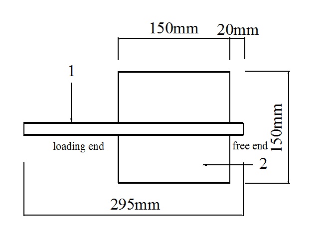
According to “Testing Code of Concrete for Port and Waterwog Engineering ” (JTJ270-06) [9], 24 cube specimens were molded. The cube dimensions is 150 mm (as is shown in Fig. 1). The water-cement ratio of the concrete is 0.69. Plain steel bars with diameter 12 mm, and yield strength 235 Mpa are used and the strength grade of concrete is C30. The liquid-solid ratio of the polymer modified cement-based coating is 0.5 and the thickness of the coating tested by “Qingdao Science Standard Testing Company” is about 0.15mm per layer. The test equipment is “SCT-10 digital film thickness measuring instrument”. The groups are listed in Table 1.
| Groups | Types of coated steel bars | Coating thickness |
|---|---|---|
| G-1 | plain steel bar | uncoated |
| G-2 | plain steel bar | 1 layer (0.15mm) |
| G-3 | plain steel bar | 2 layer (0.3mm) |
| G-4 | plain steel bar | 3 layer (0.45mm) |
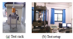
According to “Testing Code of Concrete for Port and Waterwog Engineering ” (JTJ270-06) [9], the improved method of pullout tests were used. The setup for the pullout test is given in Fig. (2). The universal testing machine is used to test the tensile strength. The slip is measured using the displacement gauge placed on the free end of the bar. The load and free end slip are recorded for each loading level during the test [10, 11].
3. TEST RESULTS AND ANALYSIS
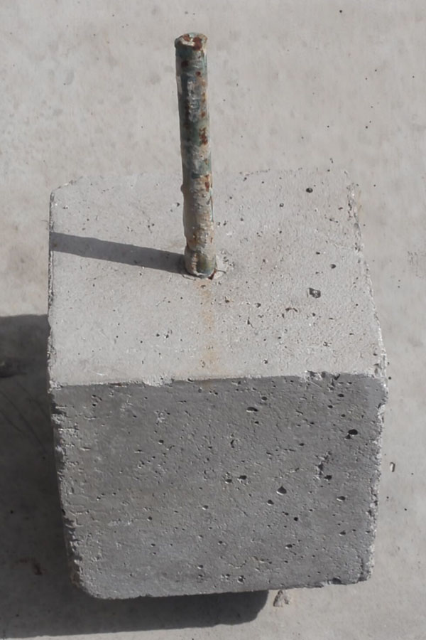
According to the pullout results, the failure modes of all of the specimens are pullout. Fig. (3) and Table 2 show the failure mode and the pullout force, respectively. The average bond stress along the whole anchorage length of steel bar is considered to be uniformly distributed and is computed as follows:

Where P is the pullout force of steel bar (N), as shown in Table 2; d is the steel bar diameter (12mm); and l is the embedment length of the steel bar (150mm); τ is the average bond stress (MPa).
| Groups | The thickness of coating | Failure mode | Pullout Force (kN) |
Bond strength (MPa) |
|---|---|---|---|---|
| G-1 | Uncoated | Pullout | 24.15 | 4.27 |
| G-2 | 1 layer (0.15mm) | Pullout | 30.80 | 5.45 |
| G-3 | 2 layer (0.3mm) | Pullout | 19.09 | 3.38 |
| G-4 | 3 layer (0.45mm) | Pullout | 15.07 | 2.67 |
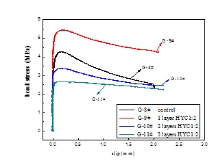
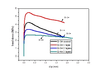
The results show that bond strength between concrete and steel bar coated with 1 layer coating could be increased, but the bond strength between concrete and steel bar coated with 2 layers and 3 layers coating could be decreased. It indicates that the bond strength could be enhanced by a suitable coating thickness.
The bond strength of steel bar embedded in concrete mainly includes two parts: 1) primarily frictional forces owing to the roughness of steel bar interface; 2) minor chemical adhesion. Suitable coating thickness could improve the roughness of steel bar interface. But when the coating is too thick, the internal structure of coating become easy to crack under tensile stress then cause the bond strength decreased.
The bond stress slip curves with different thickness of coating are illustrated in Fig. (4). Accordingly, the bond stress-slip curves between coated steel bar and concrete is similar to that of uncoated steel bar and concrete. The characteristic of bond behavior between coated steel bar and concrete at different stages can be reflected in the bond stress-slip curves. At the very beginning, the pull force is small and the slip is not obvious at the free end of steel bar, and the bond stress-slip curve remains linear. Then the slip began to appear at the free end of steel bar, showing that the adhesion force between steel bar and concrete has nearly been exhausted. Next, the slip is significantly faster and the ascending portion in the bond stress-slip became nonlinear. At the pullout stage, the several longitudinal splitting cracks developed along the weakest area of concrete cover and the applied pull force declines rapidly and the slip increases until the steel bar is pulled out. At last, the applied pull force keeps no obvious change, while the slip has a considerable increase [5]. The coating which is under tensile stress makes the specimens brittleness. So in the G-4# curve, as the force are close to peak value, descending segment is not obviously.
4. FINITE ELEMENT MODEL
4.1. Modeling Method
There are two kinds of modeling methods to realize the slip between coated steel bar and concrete: a`modeling the tests by embedding “cohesive element” [12] in concrete; b`modeling the coated steel bar and concrete using contact surface with cohesive behavior [8]. In this paper, the second method is applied to model the tests.
4.2. Modeling Process
4.2.1. The Material Constitutive Equations
Abaqus provides two kinds of models for concrete materials [13]:concrete damaged plasticity and concrete smeared cracking. In this paper, the concrete smeared cracking is applied to model the tests because it also is applied to monotonic loading of concrete. Uniaxial tension and uniaxial compression stress-strain curves of concrete are determined by “Code for design of concrete structures” (GB50010-2010) [14], as shown in Fig. (5a). The expression of uniaxial compression of concrete is given as:
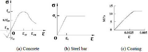


Where αc is falling segment parameter value of uniaxial compression stress-strain curves; fc.r is the representative value of uniaxial compressive strength (N/mm2); εcr is the peak compressive strain that representative value of uniaxial compression strength fcr correspond with. dc is damage evolution parameters of concrete under uniaxial compression. Ec is Young's modulus of concrete (N/mm2). The expression of uniaxial tension of concrete is given as:


Where αt is falling segment parameter value of uniaxial tension stress-strain curves; ft.r is the representative value of uniaxial tensile strength (N/mm2); εt.r is the peak tensile strain that representative value of uniaxial tensile strength correspond with. dt is damage evolution parameters of concrete under uniaxial tensile. Ec is Young's modulus of concrete (N/mm2).
The ideal elastic plastic model is used in the constitutive model of steel bar, the Young's modulus of steel bar is 2.0×10⁵ MPa, the Poisson's ratio is 0.3. The constitutive relation of the coating is measured by the test, and the Young's modulus of steel bars is 4.15×10³ MPa, the Poisson's ratio is 0.31. Fig. (5b and c) show the stress-strain curves of steel bar and coating.
4.2.2. The Instruction of the Model
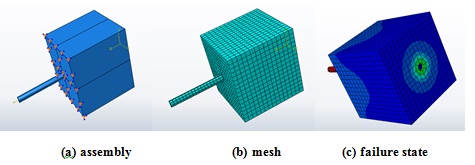
The model of plain steel bar embedded in concrete is established using Abaqus software. Fix constraint is used to model the boundary condition, because the specimens is restrained by the set-up of pullout tests (as shown in Fig. (6a). The element type is C3D8R, the mesh result is shown in Fig. (6a and b). The model is done by using contact surface with cohesive behavior. The failure state of the model and distribution of stresses is shown in Fig. (6c) What can be observed from the picture is that the stress of steel is higher than that of the concrete, but the plastic strain of concrete is less than that of steel. So the fracture section is the surface between the concrete and the coated steel.
The simulation results and test results are shown in Fig. (7). Comparing the simulation results and the test results, the bond stress slip curves of simulation results between coated steel bar and concrete are similar to bond stress slip curves of test results.
5. DISCUSSION
As shown in Table 3, the characteristic point data obtained from the numerical simulation method are not quite different from that of the characteristic point data obtained from the pullout tests. The trend of simulation results curves and test results curves are also close. So the method of modeling the coated steel bar and concrete using contact surface with cohesive behavior can reasonably predict the results of pullout tests.
| Groups | Pull-out tests results(mm) | Numerical simulation results(mm) | Δ n,u/Δ e,u |
|---|---|---|---|
| Displacement corresponding to the peak load of the pullout test (Δ e,u) |
Displacement corresponding to the peak load of the numerical simulation. (Δ n,u) | ||
| G-1 | 0.135 | 0.128 | 0.948 |
| G-2 | 0.125 | 0.133 | 1.081 |
| G-3 | 0.116 | 0.123 | 1.060 |
| G-4 | 0.137 | 0.142 | 1.036 |
CONCLUSION
The bond behaviors of polymer cement coated steel bars with concrete were studied by means of the pullout tests. The results of the tests indicate that the failure mode of the specimens is pullout and bond strength of uncoated steel bar embedded in concrete could be enhanced by suitable coating thickness. The model using contact surfaces with cohesive behavior was established. Comparing with the experimental and numerical results, the bond stress slip curves of experiment was close to that of simulation indicating that the method using contact surfaces with cohesive behavior can reasonably predict the results of pullout tests.
CONFLICT OF INTEREST
The authors confirm that this article content has no conflict of interest.
ACKNOWLEDGEMENTS
This work has been supported by National Natural Science Foundation of China (51278443). We would like to thank many friends and colleagues whose previous work contributed indirectly to this paper.


