All published articles of this journal are available on ScienceDirect.
Analysis on Calculated Length for Buckling Stability of Steel Pipe Pile Based on Energy Method
Abstract
According to the Winkler assumption, the form of the pile constraint could be simplified as bottom fixing and top free. Considering the influence from resistance of soil around pile, the equations on calculated length for buckling stability of steel pipe pile when the portions along the pile length were constrained in the uniform foundation and the layered foundation were respectively derived based on energy method and variational principles. And the application of the formulas was explained through examples. The equations are successfully applied in similar projects.
1. INTRODUCTION
The upper part of the static pipe piles is in the free state without soil constraint, and its buckling stability should be checked [1]. While the difficulty in buckling analysis on foundation pile lies in the uncertainty in determining the constraint effect of the soil around pile [2]. The literature [3] first put forward a set of empirical formulas on the calculated length lP of piles based on “m” method. Then many scholars applied the minimum potential energy principle, the variational method and the Galerkin method to the analysis on buckling stability of pile foundation and achieved certain results [4, 5].
In the buckling analysis on small-diameter steel pipe piles, the Rayleigh-Ritz method based on the energy method can simplify the solving process, and furthermore the accuracy of results can meet the engineering requirements. Based on previous studies [6-8], this paper took into account the influence of the resistance of foundation soil on piles, and derived the calculated length equation for buckling stability of the steel pipe pile by classifying the foundation soil into uniform elastic foundation and layered elastic foundation.
2. PILE FOUNDATION STABILITY ANALYSIS IN UNIFORM FOUNDATION
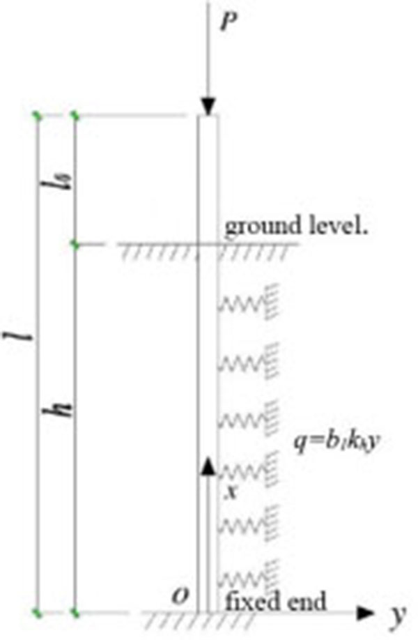
According to the actual constraints of the static pile in the project, the boundary conditions of steel pipe piles used in overall lifting process of an ancient masonry building [9] can be simplified as pile-top free and pile-end fixing, as shown in Fig. (1). As the pile-side friction resistance and the pile weight have little effect on the buckling stability of the foundation pile [10, 11], therefore, such effect was neglected in analysis. The factors with greater influences on the buckling stability of the pile foundation, e.g. the pile-end imposed load, the pile-end constraints and the pile-side horizontal resistance were only taken into account.
According to the Winkler assumption, the horizontal constraint effects of the soil around pile can be simplified into countless springs with different stiffness. In order to conform with the current foundation code, the “m” method [12] assumption was used in combination with the actual engineering conditions. Namely, the subgrade reaction coefficient kh increases linearly with depth (the value is zero on the ground level), then the distribution of resistance of soil around pile q with depth can be expressed as:

 |
(1) |
Where: b1 refers to the pile diameter; kh refers to the subgrade reaction coefficient; h refers to the buried depth of pile (m); y refers to the horizontal deflection displacement of pile.
To obtain the buckling critical load of pile body, the total potential energy of pile-soil system was established according to the solving steps in the energy method. When the pile-side friction and pile weight are not considered, the total potential energy Π of the pile-soil system consisted of three parts: the strain energy UP of the pile body, the elastic deformation energy Us of the soil around pile and the pile-top vertical load potential, V. In the range of the small elastic deformation, its specific expression is as follows:
 |
(2) |
When the pile buckling is solved by the Ritz method, the calculation must be done on the basis of the deformed system. When solving, an appropriate deflection function shall firstly be selected to obtain the internal energy and external work of the system; meanwhile, Ritz method requires that the corresponding displacement function satisfies the geometric boundary conditions.
The end-free bottom-fixing conditions are expressed as follows with reference to the deflection function of pile foundation under different boundary conditions [13], when x=0, y= 0 and y'=0; when x=h, y≠0 and y'≠ 0; the deflection function can be taken as:
 |
(3) |
Where: cn refers to undetermined coefficients.
According to the small elastic deformation theory, the elastic deformation energy, Us of the soil around pile is as follows:
 |
(4) |
The strain energy UP generated due to deflection of the corresponding pile is as follows:
 |
(5) |
The potential energy V generated from the pile-top load is as follows:
 |
(6) |
The total potential energy formula of the system obtained by substituting each potential energy equation into the total potential energy equation is as follows:
 |
(7) |
Substitute the displacement function (3) into equation (7), after arrangement, the following equation is obtained:
 |
(8) |
Where: 
 |
Where:  refers to the dimensionless length of pile; b refers to the burying ratio of pile body.
According to the principle of stationary potential energy, take variation of equation (8) to obtain:
 |
(9) |
Expand equation (9) to obtain:
 |
(10) |
The above equation is a homogeneous linear equation of X. If only limited n items are taken from the approximate expression of pile displacement function y, then the equation can be written into matrix as follows:
 |
(11) |
Where, bii=(i‒0.5)2+aiiA, bij=bji=aijA, A=2l-5π-5. The i and j values are substituted into ann and anm expressions, then the aii and aij expressions can be obtained.
To ensure that the equation set i.e. equation (11) has a non-zero solution, the coefficient determinant is required to be zero, namely:
 |
(12) |
Equation (12) is the characteristic equation of pile buckling stability. From the equation, the corresponding characteristic roots in number of n can be obtained with Jacobi method. Set the smallest positive root as xmin, the corresponding critical buckling load of pile Pcr can be obtained:
 |
(13) |
Meanwhile, the pile buckling stability calculated length lP is found as follows:
 |
(14) |
During buckling analysis on piles in practical engineering, only displacement function half-wave numbers for one or several piles need to be taken to fit the flexural displacement function y of pile, then sufficient accurate solutions can be obtained.
As the static piles used in overall lifting is not particularly long, the half-wave number for pile deflection function is taken as n=1, then the displacement function can be taken as follows:
 |
(15) |
The elastic deformation energy Us of the soil around pile can be obtained according to the small elastic deformation principle:
 |
(16) |
The strain energy UP generated due to deflection of the corresponding pile is as follows:
 |
(17) |
Also, the potential energy V generated from the pile-top load is obtained as follows:
 |
(18) |
The total potential energy formula of the system obtained by substituting each potential energy equation into the total potential energy equation is as follows:
 |
(19) |
According to the principle of stationary potential energy, take variation of the above equation to obtain:
 |
(20) |
From equation (20), the following equation can be obtained:
 |
(21) |
Then:
 |
(22) |
The critical buckling load Pcr is as follows:
 |
(23) |
Also the calculated length, lP for buckling stability of pile is as follows:
 |
(24) |
From equation (22), we know that the calculated static pile length lP used for overall lifting are mainly influenced by factors e.g. the total length l of pile, free length lO of piles, buried depth h of pile, horizontal lateral resistance coefficient, m of soil and flexural rigidity EI of pile. As the geological conditions at the specific project location is definite, i.e. the horizontal lateral resistance coefficient m is a constant; and the size of the static pile used for this project is also unchanged, namely the flexural rigidity EI is unchanged, so only the law of change of the calculated length lP along with total length, l and free length lO of pile needs to be discussed in this paper.
layer of soil to the pile bottom(22~24), now take m=0, i.e. substitute into equations (22~24) without considering the influence of soil around pile and obtain lP = 2l. When the top is free and the bottom is fixed, the stability calculated length coefficient is 2 according to the classical Euler's formula. As can be seen, when the above calculation is not considered with the influence of soil around pile, the equation derived with Ritz method in this paper is reduced as the Euler's formula.
3. STABILITY ANALYSIS ON PILE FOUNDATION IN LAYERED ELASTIC FOUNDATION
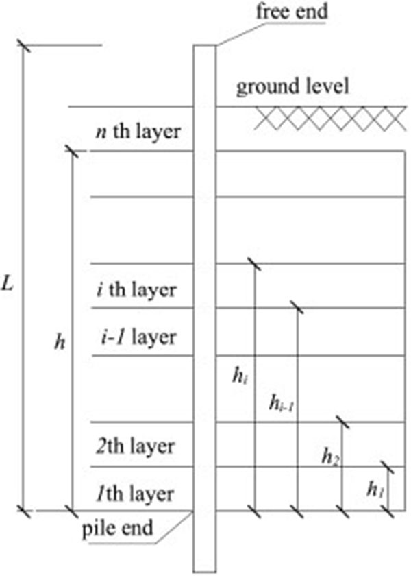
In practical engineering, the soil around pile is in layered distribution rather than uniform distribution and the subgrade reaction coefficients distributed in each layer are different. Therefore, in order to analyze the problem veritably, this paper assumes that the soil is divided into n layers (Fig. 2).

Terzaghi [14] expressed the horizontal subgrade reaction coefficient as:
 |
(25) |
Where: mh refers to variation coefficient of the subgrade reaction coefficient with depth; z refers to depth from surface; ω refers to empirical coefficient used to describe the foundation distribution pattern, non-negative; ζ refers to constant, for ease of standardization of dimension, it is recommended to be taken as 1 in literature [15];
From Equation (25), the reaction coefficient khi of ith layer of soil can be expressed as follows:
 |
(26) |
Where: mhi is the coefficient for variation of the subgrade reaction coefficient of ith layer with depth; hi is the distance from ith layer of soil to the pile bottom, so hO=0; ωi=i power series for the ith layer of soil, ranging from 0 to 1.
The foundation horizontal reaction is expressed as equation [12]:
 |
(27) |
Where: d is the pile diameter; x is the distance from the pile end; h is the buried depth of pile; and y is the horizontal deflection displacement of pile body.
Then, the distribution of the reaction of the soil around pile q with depth can be expressed as follows:
 |
(28) |
Where: n is the total number of layers of foundation soil.
Similar to equations (4-7), the total potential energy of piles in layered elastic foundation is as follows:
 |
(29) |
For convenience of calculation, assume that the certain reference subgrade reaction coefficient is khr, the subgrade reaction coefficient in ith layer of soil can be expressed as rikhr, then the above equation can be expressed as follows:
 |
(30) |
Where, the deflection function y is as follows:
 |
(31) |
From literature [12], the end free and bottom fixing conditions can be taken as follows:
 |
According to the principle of stationary potential energy, take variation from the equation (30), namely:
 |
(32) |
Substitute equation (30) into equation (32) to obtain as follows:
 |
(33) |
Equation (33) can be expressed as follows:
 |
(34) |
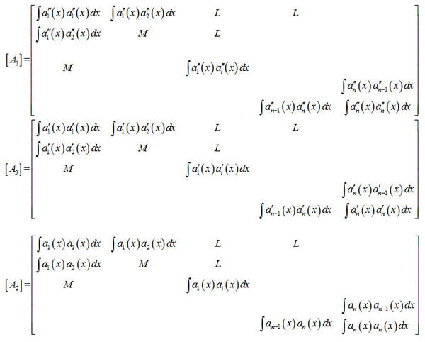
Where, [A] is the coefficient matrix and can be expressed as follows:
 |
(35) |
Where:
 |
 |
By solving the coefficient matrix, the roots in number of n can be obtained. Set the smallest positive root as xmin and obtain the critical buckling load Pcr of corresponding pile as follows:
 |
(36) |
Meanwhile, the calculated length LP for buckling stability of pile can be known as follows:
 |
(37) |
4. EXAMPLES
In the lifting work of certain ancient masonry building, Φ194mm × 6mm small diameter opening static pile was used for lifting [9]. When pressing pile, the upper pile of the soil was in free length of 1.25m, the pile was in designed buried depth of 12m, and actual buried depth of 11~14m. Consider the calculated length of pile when the upper pile of the soil was in free length of 1.25m, and in buried depth of 12m.
4.1. Calculated Length of Pile in The Case of Uniform Foundation
Refer to literature [16] for the value standard for subgrade reaction coefficient, and the physical and mechanical indicators of foundation soil are shown in Table 1 [17, 18], so refer to Table 1 for the subgrade reaction coefficient values in each layer of soil:
| Soil layer No. | Soil name | ω/% | m/MN/m4 |
|---|---|---|---|
 |
Silt (Q4al) | 22.83 | 12 |
 |
Silt (Q4al) | 18.5 | 16 |
 |
Silt (Q4al) | 17.3 | 18 |
 |
Silt (Q4al) | 18.6 | 16 |
 |
Sandy silt (Q4al) | 20.3 | 14 |
 |
Fine sand (Q4al) | 21.9 | 14 |
Where, the value can be taken as m=15MN/m4; elastic modulus of steel E=2×10⁵MPa, EI = 6.28 × 10⁶N·m2. Substitute the above known conditions into Equation (11), and obtain X=7.87, the calculated length of the pile is:
 |
4.2. Calculated Length of Pile in Case of Layered Foundation
Refer to Table 1 for the subgrade reaction coefficient values for each layer of soil; the steel pipe pile parameters are the same as the former; substitute the above known conditions into Equation (34) and obtain xmin = 6.11, then the calculated length of pile is as follows:
 |
4.3. Comparison of Results
Compared with the calculation results of the uniform foundation model, the calculated length of layered foundation model is increased by 25%, and the buckling load is reduced by 27%. It shows that the pile body is more prone to buckling under the layered soil foundation model.
5. COMPARISON OF ALGORITHMS
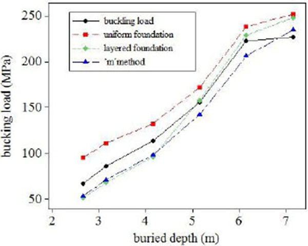
Engineering condition same as section 4, the total length of pile is 13.25m, designed buried depth of 12m and the upper pile of the soil was in free length of 1.25m. With the increase of buried depth of pile, the change trend of the buckling load as shown in Fig. (3).

As shown in Fig. (3), buckling load indicates the relationship between field measured buckling load and pile buried depth, ‘m’ method indicates the relationship between the buckling load calculated by the ‘m’ method and pile buried depth.
The measured results show that, with the increase of the buried depth, the buckling load increased significantly, but the buckling load increases slowly when the buckling depth exceeds 6 m, which is stable at 230MPa or so. Compared with the measured results, the calculated result of “m” method is conservative, and it has a great space for optimization. The curve shape which calculated by uniform foundation modal is similar to that of the measured, but the buckling value is 10% larger than measured. The calculated result of layered soil model is in good agreement with the measured data, but the calculation value of buckling load is lower than measured data in the initial stage and obviously larger when buried depth exceeds 6m. Therefore, the layered foundation model proposed in this paper can better simulate the real situation and obtaining accurate buckling loads.
CONCLUSION
This paper made an analysis on the stability of piles in uniform foundation and layered foundation based on the energy method and described the characteristics of the influences from the soil surrounding pile. The constraints of piles were simplified as bottom fixing upper free. Taking into account the influence of reaction of soil around pile, the calculated length of steel pipe pile was analyzed, and the equations on calculated length of piles in uniform foundation and layered foundation are obtained, and the application of the equations was explained in combination with examples. These equations have advantages of simple form and definitive meanings for parameter, thus easy to use, and can provide certain reference value in determining calculated length of pile on similar foundation works.
CONFLICT OF INTEREST
The authors confirm that this article content has no conflict of interest.
ACKNOWLEDGEMENTS
Declared none.


