All published articles of this journal are available on ScienceDirect.

Structural Behavior of Strengthened RC Beams in Shear using CFRP Strips
Abstract
Carbon fiber reinforced polymers (CFRP) were widely used in strengthening of reinforced concrete members in the last few years. Experimental and theoretical investigations were carried out to find the behavior of reinforced concrete beams strengthened in shear by CFRP strips. Six beams measured of 200x300x2000mm were investigated. The variables investigated in this work are orientation (vertical and inclined) and the spacing between CFRP strips.
It was found that the strengthening by CFRP strips increased the crack, yield and ultimate load by 10%, 71% and 77% respectively on average. Inclined CFRP strips show a better performance than vertical CFRP strips with same distances and increase the yield and ultimate load by 11% and 13% respectively on average. By covering all faces of specimen with CFRP strips, the yield and ultimate load increased by 82% and 95% respectively. Using the CFRP strips changed the failure model from shear to flexural by increasing the shear strength, so the ductility was increased by 198% on average. CFRP increased the strain in compression face of concrete and the value was greater than (0.003). For all strengthened specimens, there was no effect on CFRP strips.
1. INTRODUCTION
The maintenance, renovation and improvement of structural members, are probably the most critical problems in civil engineering applications. Additionally, a large number of structures built in the past using the older design codes in different parts of the world are structurally risky allowing the new design codes. Since replacement of such deficient elements of structures suffers a huge amount of community money and time, strengthening has developed the satisfactory way of improving their load carrying capacity and extending their service lives. Infrastructure deterioration caused by early drop of buildings and structure has led to the investigation of some processes for renovating or strengthening purposes.
The external bonding of high-strength carbon fiber-reinforced polymers (CFRP) to structural concrete members has extensively grown acceptance in the recent years, mainly in rehabilitation works and newly built construction. Comprehensive experimental investigations led in the past have shown that this strengthening method has several advantages over the traditional ones, particularly due to its corrosion resistance, high stiffness-to-weight ratio, improved durability and flexibility in its use over steel plates. The use of (CFRP) materials in civil infrastructure for the renovation and strengthening of reinforced concrete constructions and also for new construction has become common practice.
The following objectives of this research have been established:
- 1. To increase the database of shear strengthening using externally bonded composites.
- 2. To investigate the shear behaviour and modes of failure of RC beams with shear deficiencies after strengthening with CFRP laminates.
- 3. To study the effect of various CFRP types (strips and sheet) and shear reinforcement configurations on the shear behaviour of the beam.
- 4. To study the bond mechanism between the CFRP laminates and the concrete surface.
2. RELATED STUDIES
Historically, concrete members have been repaired by post tensioning or jacketing with new concrete in conjunction with a surface adhesive [1]. Since mid 1960s, epoxy-bonded steel plates have been used in Europe and South Africa to retrofit flexural members [2]. However, steel plates have a toughness problem exclusive to this application, because corrosion may happen along the adhesive interface. The technique of strengthening reinforced concrete buildings by externally bonded FRP laminates was started in 1980s and has since attracted many researchers around the world. It was investigated in the USA [3-8], Switzerland [9], Greece, Canada [10, 11], Japan and several other European countries.
Norris et al. (1997) [12], presented the results of an experimental and analytical study of the behavior of damaged or understrength concrete beams retrofitted with thin carbon fiber reinforced plastic (CFRP) sheets. The CFRP sheets are epoxy bonded to the tension face and web of concrete beams to enhance their flexural and shear strengths. The effect of CFRP sheets on strength and stiffness of the beams is considered for various orientations of the fibers with respect to the axis of the beam. Nineteen beams were fabricated, loaded beyond concrete cracking strength, and retrofitted with three different CFRP systems. The beams were subsequently loaded to failure. Different modes of failure and gain in the ultimate strength were observed, depending on the orientation of the fibers. Results show that the CFRP sheets can provide increase in strength and stuffiness to existing concrete beams when bonded to the web and tension face.
Khalif et al. (1998) [13], used a slight modification (Triantafillou's equation 1998) to define shear failure combined with FRP rupture. Meanwhile, the bond model of Maeda et al. 1997 [14], was used to describe shear failure combined with CFRP debonding. The two models were then presented in the AC1318-14 [15] shear design format.
In 2004, Santhakumar and Chandrasekaran [16] carried out a study on the unretrofitted RC beam designated as control beam and RC beams retrofitted using (CFRP) composites with ± 45o and 90o fiber orientations. The effect of retrofitting on uncracked and precracked beams was studied too. The finite elements adopted by ANSYS [17] were used in this study. The study concluded that numerical modeling helps to track the crack formation and propagation especially in case of retrofitted beams in which the crack patterns cannot be seen by the experimental study due to wrapping of CFRP composites. This numerical study can be used to predict the behavior of retrofitted reinforced concrete beams more precisely by assigning appropriate material properties.
Wang Wenwei and Li Guo in (2005) [18], investigated six reinforced concrete beams strengthened in flexure using (CFRP) laminates subjected to different sustaining loads. The main goal of the test was to study the effects of initial load and load history on the ultimate strength of strengthened reinforced concrete beams by externally bonded CFRP laminates. The main experimental parameters included different levels of sustaining load at the time of strengthening and load history. Test results show that sustaining load levels at the time of strengthening have important influence on the ultimate strength of strengthened reinforced concrete beams.
Zhang and Hsu (2005) [19], investigated eleven RC beams without steel shear reinforcement. After the beams were kept in the curing room for 28 days, carbon-fiber strips and fabrics made by Sika Corp were applied on both sides of the beams at various orientations with respect to the axis of the beam. Results show that the CFRP system can significantly increase the serviceability, ductility, and ultimate shear strength of a concrete beam; thus, restoring beam in shear by using CFRP is a highly effective technique. An analysis and design method for shear strengthening of externally bonded CFRP has been proposed.
Abdel-Jaber et al. (2007) [20] examined experimental results obtained from an earlier study and utilized in this research to present a reasonable model for strengthening. The experiments investigated the shear behavior of reinforced concrete beams strengthened by the attachment of different configurations and quantities of CFRP using. The application of CFRP strips to the shear spans of the beams increased the strength between 19% and 56%.
Nicolae et al. (2008) [21], presented the use of FRP composite materials for new structural members (internal reinforcements) and strengthening of existing members (externally bonded reinforcements). The advantages and disadvantages as well as the problems and constraints associated with both issues are discussed.
Mofidi and Chaallal (2011) [22], studied the shear strengthening of RC beams using externally bonded by FRP. This study reveals that the effect of transverse steel on the shear contribution of FRP is important and yet is not considered by any existing codes or guidelines. Therefore, a new design method is proposed to consider the effect of transverse steel in addition to other influencing factors on the shear contribution of FRP. Separate design equations are proposed for U-wrap and side-bonded FRP configurations. A comparison with current design guidelines has shown that the proposed model achieves a better correlation with experimental results than current design guidelines.
Alferjani et al. (2013) [23], presented the reviews of 10 articles on CFRP strengthened reinforced concrete beams. This study was an attempt to address an important practical issue that has encountered in shear strengthening of beams with CFRP laminate. Also this study proposed a simple method of applying FRP for strengthening the beam with CFRP.
Vuggumudi (2013) [24] investigated the shear performance and failure modes of RC T-beams strengthened with externally bonded GFRP sheets. In order to achieve these objectives, an extensive experimental program consisting of testing eleven, full scale RC beams was carried out. The variables investigated in this study included steel stirrups, shear span-to-depth ratio and GFRP amount.
The experimental results indicated that the contribution of externally bonded GFRP to the shear capacity is significant and depends on the variable investigated. The failures of strengthened beams are initiated with the debonding failure of FRP sheets followed by brittle shear failure. However, the shear capacity of these beams has increased as compared to the control beam which can be further improved if the debonding failure is prevented.
Ibrahim et al. (2015) [25] investigated the effective and practical approaches for strengthening load bearing walls with openings to resist extreme loads. The researcher presented the results of investigation on structural behavior of the load bearing walls of interlocking bricks system. Six specimens were prepared with the same height (1.2m) and width (0.8m), one was made from brick with thickness 0.24m and the other was made from concrete block with thickness 0.2m. Two walls were constructed with rectangular opening, and two walls were opening and strengthened with carbon fiber reinforced polymer (CFRP) strips. The test results clearly demonstrate the efficiency of using CFRP strips as a repair and strengthening technique for unreinforced load-bearing walls to increase the stiffness and ultimate bearing load.
3. RESEARCH SIGNIFICANCE
In order to take complete advantages of the potential ductility of the RC beam, it is necessary that the beam fails in flexure rather than in shear. Shear failure is tragic and happens usually without progressive cautioning. Many existing RC members are found to be deficient in shear strength and need to be renovated. Deficiencies happen due to many reasons such as insufficient shear reinforcement or decreasing in steel area due to corrosion, increased service load, and construction defects. Externally bonded reinforcement such as (CFRP) provides an excellent solution in these conditions.
4. DETAILS OF EXPRIMENTAL TEST
4.1. Out Line of Program
The experimental program consists of six beams with nominal compressive strength of
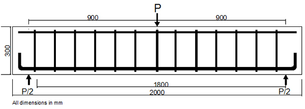
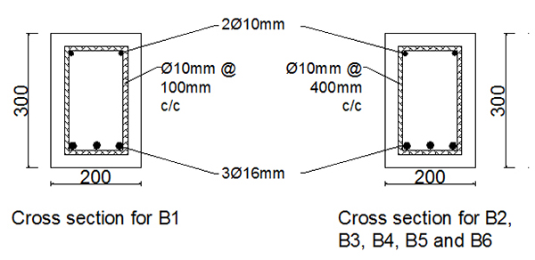
 =30MPa and each tested in point concentrated loading arrangement. All beams were constructed in the laboratory of the Engineering College of Diyala University. All beams were 200 mm wide, 300 mm height, and 2000mm length. The longitudinal bottom and top steel reinforcement were 3 ϕ 16 mm and 2 ϕ 10 mm with 430MPa and 400MPa yield strength respectively and 195GPa modulus of elasticity as illustrated in Fig. (1) and cross sections in Fig. (2). The details of shear reinforcement and CFRP specifications are shown in Table 1.
| Beam No. |
Shear Reinforcement |
CFRP Specifications | |||
|---|---|---|---|---|---|
| Width of CFRP (mm) |
Spacing CFRP(mm) |
Orientation | Type | ||
| B1 | ϕ 10mm @100mm | ----- | ----- | ----- | ----- |
| B2 | ϕ 10mm @400mm | ----- | ----- | ----- | ----- |
| B3 | ϕ 10mm @400mm | 50 | 150 | vertical | CarboDurS512 |
| B4 | ϕ 10mm @400mm | 50 | 100 | vertical | CarboDurS512 |
| B5 | ϕ 10mm @400mm | 50 | 150 | inclined | CarboDurS512 |
| B6 | ϕ 10mm @400mm | 50 | Covered all beam | SikaWrap -300 C | |
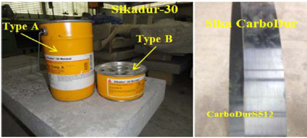
The CFRP strips used in the strengthening application were Sika CarboDurS512 unidirectional flexible strips. The structural adhesive paste used for bonding the Sika CarboDur strips to the concrete substrate was (Sikadur-30) which is high modulus and high product (Fig. 3). CFRP strips width was 50mm. Uniaxial CFRP strips were placed as a single layer for strengthening and two component epoxy adhesive was used for bonding. The application of the CFRP strips material was a simple and rapid operation. Firstly, the desired surface was smoothed by grinding and was cleaned with high air pressure. Secondly, a strong cementitious filler layer was applied to the surface to give a flat surface. Thirdly, the surface was coated with a thin layer of two component epoxy. Fourthly, one layer of the carbon fiber fabric was laid into the epoxy dry, worked into the underlying layer of epoxy by hand pressure. The temperature during application was 20 ± 2 C0 in all cases. After bonding operations were completed, specimens were cured for 7 days under laboratory conditions before testing. Properties of CFRP strips and epoxy, which are suggested by the manufacturer, are presented in Tables 2 and 3.
| Color | Light gray |
|---|---|
| Storage Conditions | Store dry at (4°-35°C). Condition material to (18°- 29°C) before using |
| Consistency | Non-sag paste |
| Pot Life | Approximately 70 minutes @ 23°C (1 qt.) |
| Mixing Ratio | Component ‟A”: Component ‟B” = 3:1 by volume |
| Density | 1.65 kg/l (mixed) |
| Tensile Properties (ASTM D-638) 7 day |
Tensile Strength (24.8 MPa) Elongation at Break 1% Modulus of Elasticity (4482 MPa) |
| Flexural Properties (ASTM D-790)14 day |
Flexural Strength (Modulus of Rupture) (46.8 MPa) Tangent Modulus of Elasticity in Bending (11721 MPa) |
| Shear Strength (ASTM D-732) 14 day |
Shear Strength (24.8 MPa) |
| Fiber type | High strength carbon fibers | ||||
|---|---|---|---|---|---|
| Base | Carbon fiber reinforced polymer with an epoxy resin matrix | ||||
| Shelf Life | Unlimited (no exposure to direct sunlight) | ||||
| Color | Black | ||||
| Tensile Strength | Mean Value 3100 MPa | ||||
| Design Value 2800 MPa | |||||
| Modulus of Elasticity | Mean Value 165000 MPa | ||||
| Design Value 160000 MPa | |||||
| Elongation at Break | 1.69% | ||||
| Design Strain | 0.85% | ||||
| Thickness | 1.2 mm | ||||
| Temperature Resistance | >150°C | ||||
| Fiber Volumetric Content | >68% | ||||
| Density | 1.60 g/cm3 | ||||
| Physical Properties | |||||
| Product | Thickness | Width | Cross Sectional Area | Tensile Force | |
| Type S512 | 1.2 mm | 50 mm | 60 mm2 | 168 kN | |
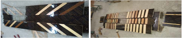
The preparation of molds for vertical and inclined CFRP is shown in Fig. (4) and the placements of CFRP and mold specimen are shown in Fig. (5).
4.2. Tested Method and Measurement
All beams were tested as a simply supported condition over an effective span 1.8m as shown in Fig. (1). For all beams, the first crack, yield and ultimate loads were measured, also the deflection under loading point.
5. TEST RESULTS
The strength characteristics of beams (crack load, yield load, ultimate load, deflection at yield and ultimate loads also the values of ductility as well) are tabulated in Table 4.
|
Beam Spe. |
Pcr (kN) |
% Diff. of crack load |
Py (kN) |
% Diff. of Yield load |
Pu (kN) |
% Diff. of Ult. load | Δy | % Diff. of Δy | Δu | % Diff. of Δu |
Ductility
|
Failure |
|---|---|---|---|---|---|---|---|---|---|---|---|---|
| B1 | 30 | ----- | 90 | ----- | 109 | ----- | 6.2 | ----- | 22.5 | ----- | 3.63 | Flexural |
| B2 | 32 | ----- | 110 | ----- | 116 | ---- | 6.0 | ----- | 8.50 | ----- | 1.32 | Shear |
| B3 | 35 | 9.40 | 171 | 55.5 | 181 | 56.0 | 9.6 | 60.0 | 11.1 | 30.6 | 1.15 | Shear |
| B4 | 35 | 9.40 | 190 | 72.7 | 210 | 81.0 | 11.6 | 93.3 | 21.4 | 151.7 | 1.84 | Flexural |
| B5 | 34 | 6.30 | 190 | 72.7 | 205 | 76.7 | 11.8 | 96.6 | 35.0 | 311.8 | 2.96 | Flexural |
| B6 | 37 | 15.6 | 200 | 81.8 | 226 | 94.8 | 11.6 | 93.3 | 34.0 | 300.0 | 2.93 | Flexural |
Excessive care was taken in marking the load at which the first crack was formed. The experimental values of the cracking loads were obtained from load-deflection diagrams.
5.1. Crack Load
From Table 4, it can be observed that the experimental crack load was increased by 9.4%, 9.4%, 6.3% and 15.6% for B3, B4, B5 and B6 respectively compared with B2. It is clear that the ratio was increased by significant ranges for B3, B4, B5 and B6 as a result of strengthening by inclined and coated CFRP.
5.2. Yield Load
Table 4 presents that the experimental yield load was increased by 55.5%, 72.2%, 72.7% and 81.8% for B3, B4, B5 and B6 respectively (compared with B2) as a result of strengthening by CFRP. Also it can be seen that by decreasing the spacing between CFRP strips from 150mm to 100mm for B3 and B4, the yield strength increased by 17.2%. Moreover as, by using the inclined CFRP the yield strength increased by 17.2% compared with same distance. Finally, by coating all faces of specimen with CFRP strips (i.e. B6), the yield strength increased by 26.3% compared with B3 specimen. It is clear that the CFRP strips increased the shear capacity of these specimens, and this strengthening is significant in decreasing the spacing of vertical embedded strips and by inclined embedded installation, as well as coated all faces of specimen.
5.3. Ultimate Load
Table 4 shows that the experimental ultimate load was increased by 56%, 81%, 76.7% and 94.8% for B3, B4, B5 and B6 respectively (compared with B2) as a result of strengthening by CFRP. Also, it can be seen that by decreasing the spacing between CFRP strips from 150mm to 100mm for B3 and B4, the yield strength increased by 25%. Moreover, by using the inclined CFRP the yield strength increased by 20.7% compared with same distance. Finally, by coating all faces of specimen with CFRP strips (i.e. B6), the yield strength increased by 38.8% compared with B3 specimen. As mentioned in section 5.2, the role of CFRP strips is clear by increasing the shear component of specimens; also it increased the flexural strength especially for B5 and B6 specimens (inclined and coated CFRP).
5.4. Ductility Index
It can be seen from Table 4 that the ductility index for the reference specimen (B1) was 3.63 and the flexural failure was observed. By increasing the spacing of stirrups with 400% (from ϕ 10mm @100mm to ϕ 10mm @400mm) as shown for B1, for B2 the ductility was decreased by 175%, and for B3 it was decreased by 215% as a result of shear sudden failure. By using the CFRP, the ductility was improved and increased by 40%, 124% and 122% for B4, B5 and B6 respectively compared with B2, and the failure mode was changed from shear to flexural. Using CFRP strips increased the shear component, so it avoided the brittle failure and the specimens were failed due to flexural, and CFRP effect was clear for B5 and B6 as increasing the flexural strength added to the increasing of shear component.
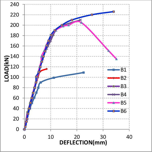
5.5. Load-Deflection Relationship
Table 4 shows the values of deflection at yield and ultimate loads that were obtained from load-deflection diagrams. The deflection at yield and ultimate load was decreased by 3% and 62% for specimens B2 compared with B1 as a result of sudden shear failure. By using CFRP for B3, B4, B5 and B6, the defection was increased by 60%, 93% 97% and 93% compared with B2 (at yield load), and by 31%, 152%, 312% and 300% compared with B2 (at ultimate) as result of increasing of yield and ultimate loads.
Fig. (6) shows the load- deflection curves for the specimens. B1 failed due to flexural stress, whereas B2 failed due to shear stress. The deflection of B2 and B3 was small because the shear failure did not made flexural reinforcement bars reach to yield and the failure is caused suddenly without giving high deflection The role of CFRP is to improve the shear strength of beam and flexural strength of B4, B5 and B6 and the failure was changed from shear to flexural. The increase in yield and ultimate loads causes a significant increase in deflection and this is shown in Fig. (6).
It is believed that cracking affects the debonding process because it results in loss of bond in the crack vicinity. This initiates debonding of the fibers that bridge the cracks. In addition, a beam with a more distributed cracking pattern tends to have FRP fibers with smaller anchorage lengths compared with the fibers on a beam with a single-line crack pattern.
B4, B5 and B6 strengthening by CFRP failed due to yielding of longitudinal and followed by separation of CFRP strips, and the cracks formed within the middle of the beams were generally vertical due to the high moment applied on this part of the beam.
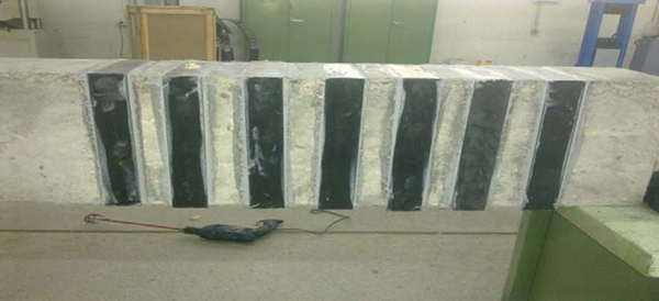
5.6. Crack Pattern
The tested beams at different stages of loading are shown in detail in Plate (1) to (6). These plates show six similar RC beams with different shear reinforcement and CFRP ratios.
The B1 cracks formed due to the high moment applied and arrangement of creation of cracking was haphazard, and cracks rose upward with the increase of the applied load. Cracks formed within the center of the beam were generally vertical due to the high moment applied on this portion of the beam. Outside the center of beam B1, the cracks became inclined due to the presence of shearing forces in addition to the moment.
B2 with shear steel reinforcement having spacing 400mm, failed with one main shear crack and a little minor shear cracks. The beam B3 was reinforced in shear only with CFRP strip failed with one main shear crack and additional surface shear cracks in the concrete cover, this produced to debonding of CFRP attached to a large chunk of concrete.
It can be inferred that cracking affects the debonding development because it results in loss of bond in the crack locality. This explained debonding of the fibers that bridge the cracks. Moreover, a beam with a more distributed cracking pattern tends to have FRP fibers with smaller anchorage lengths compared with the fibers on a beam with a single-line crack pattern.
B4, B5 and B6 strengthened by CFRP failed due to yielding of longitudinal and followed by separation of CFRP sheets, and the cracks formed within the center of the beams were generally vertical due to the high moment applied on this part of the beam.
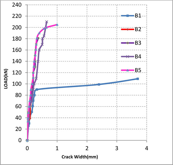
5.7. Load-crack Width Curve
The load-crack width relationship for B1 can be observed from Fig. (7). The failure was under flexural, and the stress in longitudinal bars was increased after yield load, so the crack width was increased to reach 3.7mm. In B2, the crack width was very small as shown in Fig. (7), which indicates that the failure was shear and the first crack was appearing after load (32 kN). For B3, the first crack appeared with load (35 kN), and this increase in crack load was a result of strengthening by CFRP but this strength was not enough to change failure from shear to flexural (Fig. 7). It can be observed from Fig. (7) that the crack width of B4 was greater than B3 and the failure changed from shear to flexural. In flexural failure, crack width was larger than shear failure because it allowed longitudinal bar to yield increase in crack width. The curve of B5 (Fig. 7) showed that crack width for this beam was greater than (B2, B3, B4), explaining that the CFRP inclined location was better than vertical and the failure changed from shear to flexural. We did not measure the crack for B6 because it was all covered by rubber (Table 5).
| Specimens | Pcr (kN) | Max. Crack Width (mm) | No. of cracks |
|---|---|---|---|
| B1 | 30 | 3.7 | 10 |
| B2 | 32 | 0.20 | 11 |
| B3 | 35 | 0.37 | 13 |
| B4 | 35 | 0.64 | 15 |
| B5 | 34 | 1.00 | 12 |
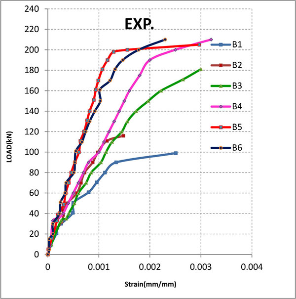
5.8. Load- concrete Stain Curves of Beams
Load concrete strain curves explain the behaviour of beams and the magnitude of strain in top face of concrete. For B1, the strain reached 0.00251 mm/mm which indicates that the failure was flexural as shown in Fig. (8). But for B2 shear failure occurred and the strain was about 0.0015 because the longitudinal bar did not reach to degree of yield (Fig. 8).
The strain result in compression zone of concrete of B3 reached to the permitted value (0.003) in ACI318-14 [17] code and this result shows the capacity of CFRP in development and increases shear strength, causing increase in flexural strength in the zone of tension and compression as mentioned in Fig. (8). For B4, the strain in concrete was greater than (0.003) as shown in Fig. (8), which increased magnitude of strain due to the increase in the CFRP strip by decreasing the spacing between it.
It can be observed from Fig. (8) for B5 that the magnitude of strain was equal to crushing strain in ACI318-14 [17] code (0.003). This value of strain explains that the failure changed from shear to flexural. The strain in B6 was about 0.0023 and this reduction in value caused because the demic point was fixed in the rubber and this rubber restricted the strain reading to an approximate value (Fig. 8).
CONCLUSION
- The strengthening by CFRP strips increased the crack, yield and ultimate loads by 10%, 71% and 77%, respectively on average.
- For shear strengthening, inclined CFRP-strips showed a better performance than vertical CFRP strips with same distances and increased the yield and ultimate load by 11% and 13%, respectively.
- Decreasing the spacing between the vertical CFRP-strips by 33% gave increase in the yield and ultimate loads by 11% and 16%, respectively.
- By covering all faces of specimen with CFRP strips, the yield and ultimate load increased by 82% and 95%, respectively.
- Using CFRP strips changed the failure model from shear to flexural by increasing the shear strength, so the ductility was increased by 198% on average.
- By using the CFRP, the defection was increased at yield and ultimate load by 85% and 198% on average respectively, as a result of increasing the yield and ultimate loads.
- CFRP increased the strain in compression face of concrete and the value was greater than 0.003.
- For all strengthened specimens, there was no failure in CFRP strips.
- The crack width for specimen having no CFRP was less than specimens strengthened by CFRP because the failure was shear, but in other beams fail under flexural failure.
CONFLICT OF INTEREST
The authors confirm that this article content has no conflict of interest.
ACKNOWLEDGEMENTS
Declared none.

