All published articles of this journal are available on ScienceDirect.

Passive Control Systems for the Blast Enhancement of Glazing Curtain Walls Under Explosive Loads
Abstract
Glass curtain walls are used in modern buildings as envelopes for wide surfaces due to a multitude of aspects. In glass curtain walls, tensile brittle panels are connected - through mechanical or adhesive joints - with steel frameworks or aluminum bracing systems, and due to the interaction of several structural components, the behaviour of the so assembled system is complex to predict, especially under exceptional loading conditions such as explosive events. In the paper, glazing curtain walls are investigated by means of Finite-Element (FE) numerical simulations, under the effect of air blast pressures of variable intensity. Their typical dynamic behaviour and criticalities under high-strain impact loads are first analyzed. By means of extended nonlinear dynamic FE parametric studies, innovative devices are applied to traditional curtain walls, at their support points, in order to improve their expected dynamic response. Two possible solutions, namely consisting of viscoelastic (VE) or elasto-plastic (PL) dampers, are proposed as passive control systems for the mitigation of maximum effects in the façade components deriving from the incoming blast pressures. As shown, although characterized by specific intrinsic mechanical behaviours, either VE or PL dampers can offer beneficial structural effects. In the first case, major advantages for the façade components derive from the additional flexibility and damping capacities of VE devices. In the latter case, PL dampers introduce additional plastic energy dissipation in the traditional curtain wall assembly, hence allowing preventing severe damage in the glazing components. It is thus expected that the current outcomes could represent a valid background for further experimental validation as well as detailed assessment and optimization of the proposed design concept.
1. INTRODUCTION
Over the last years, practical examples of structural glass applications in buildings as load-carrying elements and complex structural assemblies have been largely increased, due to a multitude of aesthetic, lightening, thermal motivations. Several studies, experimental researches, Finite-Element investigations have been focused on the analysis of single glass components or assemblies under specific loading and boundary configurations, in order to provide design recommendations, practical rules, novel assemblies concepts, etc. Various studies have been also related to fully glass façades and curtain wall systems. Their structural behaviour is typically associated to the interaction of multiple components, such as glass panels, appropriate mechanical or adhesive connections and bracing metal systems (e.g. frames, cable-nets, etc.). While the structural response of these glazing assemblies under ordinary loads can be rationally estimated and optimized, careful consideration should be paid in their design under exceptional loads, such as explosive events typically characterized by high-strain impulsive pressures and abrupt release of energy. Due to the intrinsic tensile brittle mechanical behaviour of glass and its vulnerability to impacts or high-strain loads, the achievement of an optimal structural behaviour for a given glazing system under blast events directly reflects on the protection of occupants and minimization of possible injures. To this aim, experimental and Finite-Element (FE) studies related to the dynamic response of single glass panels and the interaction with the restraints have been discussed [1-4]. Numerical modelling concepts and validations have been proposed [5-7]. Multi-hazard design concepts and simplified analytical methods have been proposed [8, 9] for glazing façades under explosive events. The application of cementitious crash materials for the implementation of innovative connectors in cable-supported façades under impulsive loads has been assessed [10, 11], while the feasibility of passive control devices for cable-net glazing systems under blast has been explored by means of FE and analytical models [12-14].
In this paper, in accordance with C. Amadio et al., [15], the dynamic response of a stick curtain wall subjected to air blast loads is investigated by means of FE dynamic nonlinear simulations [16]. The stick curtain wall solution typically consists of modular units composed of a laminated (and/or insulated) glass panel attached to a split screw spline mullion system by means of a continuous bead of structural sealant. Four steel rigid brackets are then used to connect each modular unit to the structural backup. The feasibility and potential of passive control systems for the mitigation of blast effects and optimization of the façade components is then assessed. Over the past decades, passive, semi-active or active control systems have been largely applied in buildings and infrastructures, as additional sources of structural damping, stiffness or strength – especially for vibration control applications and mitigation of wind or earthquake effects [17-24]. In the current investigation, calibration and validation of FE models are first provided towards experimental data of literature and simple analytical formulations. Several blast loading scenarios are then taken into account, so that the criticalities in the façade components under high or medium/low blast pressures could be emphasized. In order to avoid severe damage in the glass panels, as well as in the supporting frame and the structural background, hence minimizing possible injures, two typologies of dissipative devices are introduced at the support points of each modular unit. In the first case, viscoelastic (VE) solid dampers able to provide additional flexibility at the façade restraints and significant damping capacities are proposed. Their structural effects are compared with the benefits deriving from elasto-plastic (PL) dampers (e.g. ADAS), introduced at the points of connections of the bracing frame and able to provide energy dissipation by means of yielding of their steel components. The effects deriving from both the explored device typologies are critically discussed, on the basis of parametric FE nonlinear dynamic simulations. As shown, when the devices components are properly calibrated, the dynamic response of a traditional curtain wall can be markedly improved, and damage on its components and occupants prevented.
Based on the discussed design concepts and results, it is expected that the current outcome could represent a reference background for further experimental validation, FE investigations and implementation of design recommendations.
2. CURTAIN WALLS
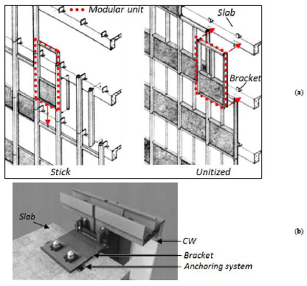
Curtain walls (CW) are largely used in modern practice, due to a multitude of aspects, both in new buildings as well as in the form of re-cladding envelopes for existing structural systems. The typical CW consists of ‘pre-glazed’ units (e.g. manufactured under controlled conditions), that is modular assemblies obtained by connecting metal profiles or steel frameworks with glass panels or other cladding elements (e.g. stainless steel metal panels, insulated spandrels, etc.). Typically spanning from floor to floor, CW modular units are usually attached to the floors by means of special rigid brackets (Fig. 1). Wind and gravity loads, as well as other external pressures, are thus transferred to the building at the level of inter-storey floors.
The method of fabrication and installation of CWs allows classifying this façade typology in ‘stick’ and ‘unitized’ systems. In the first case, the basic modular unit consists of a single glass (or other infill) panel and metal mullions, which is installed on-site piece by piece. Depending on the spacing of columns and the design loads, in the typical stick modular unit the bracing mullions can be spaced from ≈1.2m to ≈1.8m. In ‘unitized’ CWs, conversely, the modular assembly is composed of large units (e.g. more than a single panel). A direct effect deriving from the CWs technology is that stick or unitized CWs can be more or less suitable solutions for large envelopes and building enclosures with modular/repetitive design and/or complex geometries.
2.1. Case Study
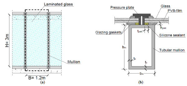
In this work, as a reference case study, a modular unit belonging to a stick CW is investigated. In it, four key components are involved, and namely (i) the glass panel, (ii) the supporting frame; (iii) the connection between the glass panel and the frame, as well as (iv) the connection at the interface between the frame restraints and the structural background. The studied façade unit is H= 3m tall and B= 1.20m wide (Fig. 2a). A laminated glass (LG) panel having a total nominal thickness equal to 28.52 mm, e.g. obtained by assembling two 12 mm thick glass lites and a middle 4.52 mm Polyvinyl-Butyral (PVB®) interlayer, is taken into account. The glass panel is continuously supported along the four edges by means of an aluminum frame (hm= 135mm, bm= 70mm, th= tb= 10mm, Fig. (2b)), while the physical interaction between the glass lite and the frame is ensured by a continuous layer of structural sealant (thickness tjoint= 7mm and width hjoint= 21mm). Glazing gaskets are also used to prevent possible rotations and splitting of the sealant joints, so that the original position of the glass panel could be kept fix (e.g. Fig. (2b)). Fully rigid steel brackets provide, finally, a strong restraint between the façade unit and the building, hence ensuring possible local deformations under the effects of high-strain impulsive loads such as explosion.
3. BLAST DESIGN PRINCIPLES AND ENHANCEMENT OF GLAZED CURTAIN WALLS
Under high impulsive external loads, the glazing system should be able to offer appropriate resistance, in order to avoid the collapse of the structural system. At the same time, the building envelope should be as flexible as possible, so that the incoming blast pressure should be properly stored in each façade component and the possible number of injured occupants could be minimized.
For several decades, ‘laminated glass’ panels able to flex after glass cracking but at the same time to hold the cracked panes together, thus limiting the scattering of glass fragments, have been considered the conventional blast-resistant glazing system [26], since able to provide additional plasticity to typical tensile brittle glass structures, hence guaranteeing large post-cracked deformations and blast energy absorption, and preserving possible injures. Anti-shatter and blast mitigation films have been also proposed for the blast mitigation of glass systems, so that flying glass due to explosions could be avoided and major damages due to shards minimized [27, 28]. Special blast resistant ‘glass block systems’ have also been developed, enhancing traditional glass block structures by means of appropriate silicone sealants and spacers, so that flexible, resistant and blast pressure absorbing units could be obtained [29]. In this work, the possible application of viscoelastic (VE) or elasto-plastic (PL) dampers at the points of connection between the curtain wall and the structural background is assessed by means of Finite-Element calculations. For both the devices typologies –characterized by specific mechanical behaviours and intrinsic advantages or limitations – critical discussion is provided for some configurations of practical interest.
3.1. Viscoelastic Solid Dampers (VE)
Viscoelastic solid dampers have been largely used in buildings and structural systems (Fig. 3). First applications of VE dampers to structures was in the form of shock absorbers for military and aerospace applications, while successively – due to their intrinsic high damping and flexibility capacities – their application has been extended to buildings and infrastructural systems under seismic, wind or impact vibrations [19-21].
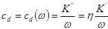
The main advantages of VE dampers are in fact given by (i) activation at very low displacements and incoming impulse, (ii) availability of restoring force and (iii) almost linear mechanical behaviour, thus resulting in simplified design rules and recommendations. Recent applications of VE dampers to glazing systems have been proposed [13, 15], for example, where it was shown through analytical models and FE nonlinear dynamic simulations that VE devices introduced at the points of connection between the glass panels and the metal framework can have multiple benefits on the behavioural trends of the entire system, e.g. mainly deriving from the introduction of additional flexibility and damping capacities. Under well-defined loading conditions (e.g. operating frequency and temperature), the key parameters of a VE device are in fact the damping ratio cd deriving from the VE compound and the corresponding elastic stiffness kd ≡ K', where [18]:
 |
(1) |
with ω the damper operating frequency, η the loss factor of the VE compound and,
 |
(2) |
 |
(3) |
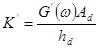
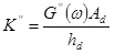
the storage and loss stiffnesses respectively, defined as a function of the storage and loss shear moduli G'(ω), G'(ω); the total shear area Ad of the VE layer and its thickness hd.
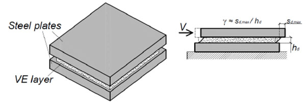
Based on Eqs. (1)-(3), once the operating frequency ω and expected loading conditions (e.g. temperature and strain level) are known, a given VE solid damper can be rationally described in the form of a linear dashpot (e.g. cd) and spring component (e.g. kd ≡ K'). At the same time, however, careful consideration should be paid in the design of VE dampers, so that (a) possible failure mechanisms, e.g. maximum shear strains γ or deformations sd,max in the VE layer would not provide tearing in the layer itself (Fig. 3):
 |
(4) |
and (b) possible delaminations at the interface between the VE layer and the steel supports could be avoided.
Finally, (c) design rules of general validity should properly consider the moderate sensitivity of the constitutive VE mechanical properties to frequency, as well as temperature conditions. As a result, Finite-Element numerical studies discussed in this work were carried out by taking into account as a reference configuration the operational frequency ω of the studied CW modular unit, under the hypothesis of constant temperature. Since the aim of this research work is to provide a first assessment of the possible structural effects of VE devices introduced in conventional curtain walls, in first approximation, the elastic parameters of the VE system (e.g. Eqs.(1-3)) were calculated as a function of G'(ω), with ω the fundamental pulsation of the curtain wall modular unit (see Section 3.3) and G'(ω) derived from experimental literature works (G'(ω) ≈ 1MPa and η ≈ 0.6 [20, 22]).
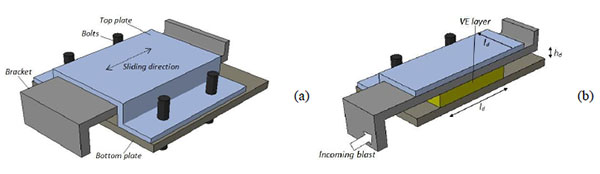
The typical viscoelastic (VE) device consists of two metallic plates and a middle VE layer, namely composed of natural rubber. The VE layer is supposed to have a nominal thickness hd and a square base shape of surface Ad (with ld the edge size (Table 1) and (Fig. 4). The lower and bottom plates are directly attached to the structural backup (e.g. the reinforced concrete slab) by means of anchoring bolts, whereas the rigid steel bracket supporting the tubular frame is properly constrained by means of inner steel plates enabling possible crushing of the VE layer and rotations of the steel bracket within the device. In this manner, due to the assigned design explosion, the full VE device is able to slide only in the direction perpendicular to the plane of the curtain wall Fig. 4.
| Device # |
Rk(Eq.(12)) [-] |
hd [mm] |
ld [mm] |
cd (Eq.(1)) [N/m] |
|---|---|---|---|---|
| VE-01 | 4 | 25 | 120 | 27149 |
| VE-02 | 2 | 25 | 85 | 19197 |
| VE-03 | 0.5 | 25 | 40 | 9599 |
3.2. Elasto-Plastic Devices (PL)
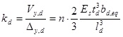
Yielding metal dampers able to dissipate the incoming energy due to inelastic deformation of metals are also widely used in civil constructions [23, 24]. Often, these elasto-plastic mechanisms consist in triangular or X-shaped mild steel plates, so that an almost uniform yielding throughout the device could be offered. ADAS (added-damping-and-stiffness) dampers, for example, have been largely used in civil buildings, especially for the vibration control of buildings under earthquake loads. From a practical point of view, the simplest way to mechanically reproduce the mechanical response of ADAS devices is the use of an elasto-plastic bi-linear constitutive behaviour, in accordance with A.S. Whittaker et al., [23], where the key input parameter are the elastic shear stiffness kd and the shear yielding force Vy,d.
 |
(5) |
 |
(6) |
In Eqs. (5 and 6), Es and σy,s denote respectively the Young’s modulus of steel and its yielding stress, while td and ld (with bd,eq = ld/2) signify the nominal dimensions of the ADAS yielding components (Fig. 5), n is the number of metal plates and
 |
(7) |
represents the yielding shear displacement of the ADAS device.
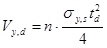
In Fig. (5), a possible ADAS damper for application in CW assemblies is proposed. The device consists of (i) a rigid metal bracket (e.g. representing the connection between the curtain wall mullions and the device), (ii) a well calibrated number n of X-shaped steel components with ld and td nominal dimensions and (iii) a system of anchoring bolts and rigid plates able to provide a fully rigid connection between the ADAS damper and the sub-structure (e.g. the concrete slab).
When subjected to external loads impacting on the CW surface, the CW modular unit transfers a maximum reaction force to the ADAS device. As far as this reaction force does not exceeds the shear yielding force Vy,d of the ADAS damper, the device behaves as a linear elastic support for the CW assembly. Conversely, when subjected to shear loads exceeding Vy,d, the ADAS mechanism is activated and the bracket slides in the direction perpendicular to the façade, hence providing plastic dissipation of the incoming energy. A bottom steel plate rigidly connected to the concrete slab ensures the appropriate position of the bracket when the dissipative mechanisms activates. The same bottom plate provides an appropriate transmission of vertical loads to the structural background.
3.3. Equivalent Dynamic Properties of the Curtain Wall System
To preliminarily estimate the dynamic behavioural trends of the studied curtain wall equipped by four VE or PL devices introduced at the support points of the CW unit, the dynamic parameters (e.g. equivalent elastic stiffness ktot, damping ctot and mass Mtot) may be rationally estimated by considering a simplified single-degree-of-freedom (SDOF) analytical model.
Certainly, an accurate analytical calculation of the expected dynamic response for the examined glazing system would require a precise calculation of its equivalent dynamic parameters in both the elastic (e.g. uncracked) and post-cracked stages, due to the typical tensile brittle behaviour of glass plates and almost elasto-plastic constitutive response of the PVB foils. Several studies have been in fact dedicated to the calibration of appropriate transformation coefficients able to take into account – throughout the full dynamic response of a glass panel system – the actual mechanical behaviour of each component [30, 31], so that simplified but accurate dynamic calculations could be developed in accordance with classical theories of structural dynamics [32]. As a result, the formulations here provided are intended for the estimation of the fundamental period of vibration T* only for CW assemblies with fully elastic behaviour. This assumption is rationally justified by the aim of this research contribution, since it is expected that the proposed VE or PL dampers could avoid the development of possible damage mechanisms in the CW assembly components (e.g. glass cracking, interlayer yielding and tearing, frame damage, etc.).
In accordance with the schematic CW modular unit depicted in (Fig. 6) it is in fact expected that – due to the additional VE or PL dissipative dampers – the glazing system would behave as a structural assembly in which:
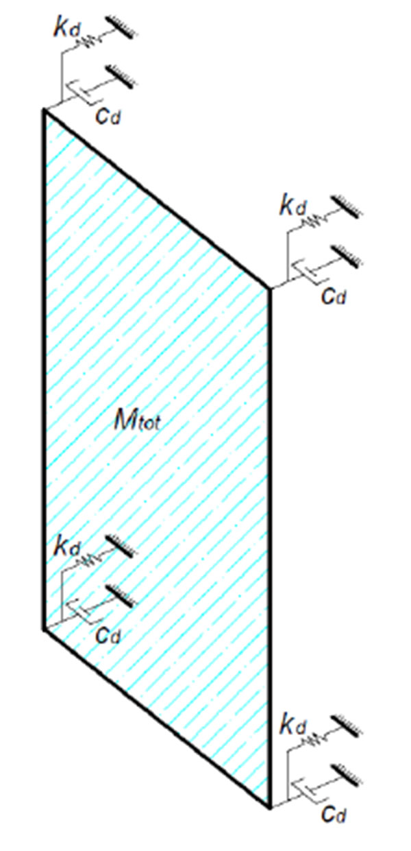
- Mtot is the equivalent mass, e.g. namely represented by the mass of the glass panel (Mglass), the interlayer (Mint) and the supporting metal frame (Mframe):
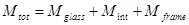 |
(8) |
- ktot represents the elastic stiffness deriving from the VE or PL devices themselves (e.g. assuming a fully rigid continuous support provided by the bracing frame to the glass panel edges):
 |
(9) |
where kd is given by Eqs.(2) or (5), for VE and PL devices respectively;
- ctot is the total damping of the CW modular unit, and should be properly calculated. Possible damping contributions could in fact derive from material (e.g. the PVB foils bonding together the glass plies, cint), aeroelastic phenomena (cair) and dissipation mechanisms deriving from the proposed devices (cd):
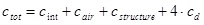 |
(10) |
In Eq. (10), specifically, cd is given by Eq. (1) in presence of VE devices (cd for the CW assembly with PL dampers). The aeroelastic, structural and material damping contributions, at the same time, are preliminary neglected. Scarce experimental studies are in fact available in literature for an appropriate assessment of the damping capacities of laminated glass panels and CWs under blast loads. In any case, such data are often in the order of 1-2% [33-37].
In conclusion, once the equivalent mass Mtot and stiffness ktot of the CW unit are calculated by means of Eqs. (8) and (9), its fundamental period of vibration is given by:
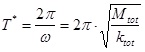 |
(11) |
Based on Eq. (11), it can be noticed that as far as the flexibility provided by devices increases, the fundamental period of the assembled system increases, hence requiring an appropriate calibration of the proposed devices.
In order to assess the accuracy of Eq. (11), extended analytical calculations were carried out on the CW assembly of Fig. (2), by taking into account a wide set of supports stiffnesses ktot.
The elastic stiffness ktot, specifically, was expressed in the form of the non-dimensional ratio:
 |
(12) |
with,
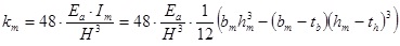 |
(13) |
representing the bending stiffness of a single tubular mullion, Ea the Young’s modulus of aluminum and hm, bm, tm, tb its nominal dimensions (Fig. 2b), with H the total CW span (Fig. 2a).
The so calculated vibration periods T* (with 0 < RK < 10) are collected in (Fig. 7a), and compared with the corresponding TFE values. These latter fundamental periods of vibration TFE, in particular, were obtained by means of FE frequency analyses carried out in ABAQUS/Standard, on FE models representative of the CW unit of Fig. (2), assembled and calibrated as discussed in Section 4.3. In the same (Fig. 7a), T0= 0.0511s represents the fundamental period of the CW modular unit with fully rigid supports (ABAQUS/Standard).
As shown, a rather good agreement was generally found between calculations given by Eq.(11) and the corresponding FE estimations. Parametric calculations highlighted, for the studied CW assembly, that as far as the frame supports behave as rigid restraints (e.g. RK > ≈5), the fundamental modal shape of the glazing system does not modify and is almost coincident with the deformed configuration of a pinned-pinned beam (e.g. blue-to-red contour plot of (Fig. 7a) (ABAQUS/Standard)). For the same range of stiffness ratios RK > ≈5, small variations can be seen in terms of the reference vibration period To Fig. 7b.
For lower RK ratios (RK < ≈5), conversely, the CW assembly almost behaves as a rigid body on flexible supports and T0 further increases, in accordance with the exponential law provided in Fig. (7b).
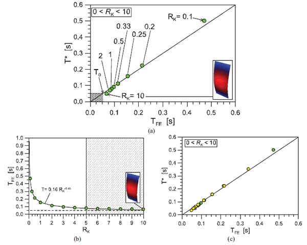
The close agreement between analytical estimations given by Eq.(11) was then further assessed by means of frequency modal analyses carried out in ABAQUS on additional CW modular units. In this latter case, in order to emphasize the general validity of Eq. (11), variation of the RK ratio was taken into account (with 0 < RK < 10) for several CW modular units. The difference between these latter CW assemblies and the case study of Fig. (2) was represented by (i) the tubular section of the frame elements (th= tb= 6mm, 8mm, 15mm, 20mm; hm= 100mm, 150mm), (ii) the thickness of the glass panels (10mm, 15mm, 19mm), (iii) the overall BxH dimensions of the CW unit (H= 2.5m, 3.5m; B= 1.5m, 1.8m). The so obtained comparisons are collected in Fig. (7c).
4. FINITE-ELEMENT INVESTIGATION
4.1. General Numerical Approach
Nonlinear dynamic Finite-Element numerical simulations were then carried out on the examined façade modular unit, by taking into account several possible applications of VE or PL devices, as well as various blast loading scenarios.
Tables 1 and 2 summarize a selection of the main input parameters considered throughout the performed exploratory numerical investigations.
| Device # |
Rk(Eq.(12)) [-] |
ld [mm] |
td [mm] |
n [-] |
Vy,d(Eq.(6)) [kN] |
|---|---|---|---|---|---|
| PL-01 | 36 | 100 | 10 | 3 | 17.6 |
| PL-02 | 36 | 70 | 8 | 3 | 10.9 |
| PL-03 | 38 | 100 | 10 | 6 | 22.6 |
| PL-04 | 9 | 200 | 10 | 3 | 17.6 |
4.2. Air Blast Loading Scenarios
In order to assess the dynamic behaviour of the studied façade module to impact pressures of various intensities, as well as the structural efficiency of VE or PL devices, several air blast loading scenarios were taken into account. Although the pressure wave impacting on a building depends on several parameters (e.g. the equivalent mass MTNT of explosive, the stand-off distance HTNT of the explosive from the building, etc.), the corresponding time-pressure waves can be idealized by means of approximating fitting curves.
In this work, explosive air blast waves corresponding to the free field detonations of 150kg, 75kg and 25kg respectively – at a stand-off distance of 30m from the CW surface – were taken into account. (Fig. 8) shows the corresponding pressure-time idealized curves, with BLAST-150, BLAST-75 and BLAST-25 denoting the respective MTNT charges. The positive phase is calculated in accordance with the semi-empirical modified Friedlander equation [38, 39]:
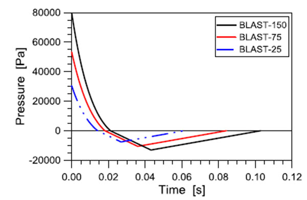
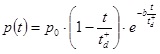 |
(14) |
with
- po denoting the maximum peak of reflected pressure
- b the decay parameter, e.g. a coefficient able to describe the rate of decay of the pressure-time curve
- t+d signifying the positive phase duration of the air blast wave
while the negative phase, typically characterized in terms of negative duration t-d and under-pressure peak po,min, is described in the form of a bi-linear relationship.
4.3. FE-Model Assembly of the Curtain Wall Modular Unit
Careful consideration was paid for a rational assembly and mechanical calibration of each façade unit component, as well as their reciprocal interaction, in order to correctly reproduce the expected dynamic and preserve the computational cost of nonlinear dynamic simulations. First, the modular unit with fully rigid brackets was investigated (M01 model, (Fig. 9). The difference between the so assembled and calibrated M01 model was then given by the introduction, at the point supports of the metal frame, of equivalent springs and dashpots able to reproduce – both in the case of VE or PL devices – the mechanical behaviour of dampers with geometrical and mechanical properties listed in Tables 1 and 2 (detail of Fig. 9).
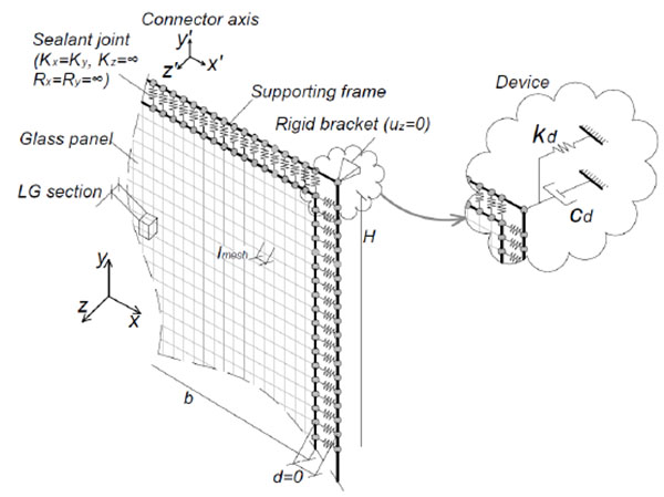
In accordance with C. Amadio et al., [15], the laminated glass panel was modelled in the form of S4R 4-node type, composite quadrilateral stress/displacement shell elements with reduced integration and large-strain formulation. Five integration points through the thickness of the composite section were taken into account, while the nominal cross section of the panel was considered. This modelling approach, typically characterized by low computational cost compared to fully 3D models, is also in agreement with Larcher et al. [6], where the comparison of FE numerical results obtained from laminated glass layered shell models or 3D solid models showed a close agreement between them, especially in the case of failure of both the glass plies. The supporting frame (e.g. the aluminium mullions and transoms) was then modelled of three-dimensional beam elements (B31), with equivalent cross-sectional properties able to reproduce the actual geometry and inertial contributions of the examined case study (Fig. 2b).
Meshing of the frame was based on beam elements with 50mm of length. In the case of the laminated glass panel, a free meshing technique was used, so that the reference element size lmesh could be set equal to 50mm along the panels edges, and decreased up to 15mm towards the centre of the panel (e.g. where maximum tensile stresses were expected). In this manner, mechanical connectors able to reproduce the effects of continuous sealant joints were introduced along the panel edges, in the form of node-to-node joints interconnecting each glass edge node and the corresponding mesh node in the metal frame (Fig. 9). These equivalent springs, representative the bead of silicone sealant interposed between the glass panel and the frame, were characterized in terms of in-plane stiffness Kx and Ky (Fig. 9), with Kz = ∞ – in accordance with the discussed simplified modelling assumptions – and fully rigid rotational stiffnesses Rx, Ry. The corresponding in-plane stiffnesses Kx and Ky were calculated by taking into account the influence length of each connector and the mechanical properties of sealants of practical use in practice for structural glass applications (see Section 4.3.1).
Structural, material and aeroelastic damping terms, based on Eq. (10), were fully neglected in this exploratory investigation, so that the main contributions of VE or PL dampers could be emphasized and assessed.
4.3.1. Materials
Regarding the mechanical characterization of materials, both the aluminum and the silicone sealant were described in the form of idealized elasto-plastic constitutive behaviours, by taking into account nominal or experimental parameters available in literature. In the case of aluminum, the Young modulus, Poisson ratio and density were assumed equal to Ea = 70GPa, νa= 0.3 and ρa= 2700 Kg/m3, respectively, with σy,a= 200MPa the yielding stress and σu,a= 280MPa the stress at failure [40]. Concerning the structural silicone joints, otherwise, average elastic mechanical properties of sealants of typical use in the practice of glazing systems were considered. An average Young modulus Ejoint= 0.7MPa was taken into account, with σjoint,u = τjoint,u = 1.2MPa and εjoint,u =400% the corresponding tensile/shear resistance and ultimate strain [41, 42]. A tensile brittle mechanical damage model was also implemented in the equivalent connectors, so that at the first attainment of the ultimate stress (e.g. σjoint,max = σjoint,u) or strain (e.g. εjoint,max = εjoint,u) configurations, the single connector could be deactivated and the possible detachment of the glass panel from the tubular frame could be considered.
4.3.1.1. Glass
The tensile brittle behaviour of glass was then taken into account by means of the ‘brittle cracking’ material model available in ABAQUS/Explicit library [16]. In it, a Rankine failure criterion is used for the crack detection and glass is assumed to behave linear elastically until the maximum principal tensile stress exceeds the characteristic tensile strength σRk,g. As input parameters, glass was described as homogeneous, isotropic material with nominal Young modulus (Eg= 70GPa), Poisson ratio (νg= 0.23) and density (ρg= 2500 Kg/m3) [43]. A fully indefinitely linear elastic behaviour was then considered to characterize the compressive response of glass. This assumption was justified by the typically high compressive resistance of glass (with σc,g ≈ 1000MPa the theoretical value [43]), as well as by the specific loading and boundary conditions taken into account in this research work. Careful consideration, conversely, was given to assessment of the characteristic tensile strength. As also discussed in detail by Bedon et al., [44], due to the impulsive nature of explosive loads, strain rate effects should be properly taken into account. A possible tool is represented by the use of magnified nominal characteristic tensile strengths given by production standards. The tensile strength of glass strictly depends in fact on the duration of the applied loads. Under exceptional high-speed loads like explosions, with a typical duration of ≈0.005-0.025 seconds, tensile strengths of glass are generally assumed higher than the corresponding nominal values, due to the increased reference probability of failure. In this paper, in accordance with Bedon et al., [44], the static bending strengths σRk,g of annealed glass (45MPa) was replaced with “dynamic” reference strength of ≈85MPa.
The post-cracked behaviour was then described by means of the “brittle shear” retention model available in ABAQUS/Explicit [16]. Consequently, the cracked shear modulus of glass
 was estimated in each simulation as a fraction of the uncracked shear modulus Gg:
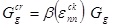 |
(15) |
For the shear retention factor
 , being its value dependent on the crack opening strain
 (
(
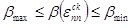 , with
 before crack initiation and
 at the complete loss of aggregate interlock), an exponential low was used:
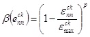 |
(16) |
with
 the ultimate crack opening strain. The material parameter p, based on earlier calibration [44, 45], was assumed equal to p= 5. The “brittle failure” sub-option was also taken into account in simulations, so that the cracked glass elements were physically removed from the mesh at the attainment of a critical displacement uck:
 |
(17) |
with Gf,g the glass fracture energy equal to Gf,g= 3J/m2 [44, 45].
4.3.1.2. PVB
The mechanical behaviour of PVB foils is also strictly strain-rate and temperature dependent. Differing from the typical non-linear viscoelastic behaviour under low-strain rates, impulsive and high-strain rates are commonly associated to an elasto-plastic mechanical response for PVB-films and high elastic stiffness Eint.
As also highlighted by Bedon et al. [44], based on dynamic test results of literature, a detailed and rigorous description of its constitutive characteristic curve would require the implementation of hyperelastic material laws. X. Zhang et al. [46], for example, the mechanical constitutive response of PVB foils in laminated glass windows under the dynamic impact of wood debris (e.g. for application to automotive products) has been deeply investigated – throughout the full pre-cracked and post-cracked phases –by means of high-strain rate experiments and calibrated FE-numerical models.
In this work, in accordance with the FE mechanical calibration proposed [44], a stress-strain characteristic curve with σy,int= 11MPa the yielding strength, εu,int= 300% the ultimate strain and Eint= 500MPa the Young modulus was used. For FE-modelling purposes, hardening effects were totally neglected and an idealized elasto-plastic σ-ε relationship was taken into account (with σu,int≡ σy,int the ultimate strength). Material density and Poisson’s ratio were finally set equal to ρint= 1100kg/m3 and νint= 0.49, respectively.
Certainly, the full post-cracked dynamic analysis of the examined CW modular unit would require careful assessment of the mechanical modelling assumptions for all the CW components (e.g. characteristic behaviour of materials in the post-cracked stage and, for example, proper description of glass-to-interlayer interaction or possible tearing and delaminations in the post-failure stage). The numerical investigations presented in this paper are based in fact on a fully bonding interaction between glass and PVB layers, up to failure. However, since the purpose of this exploratory research is the development of preliminary recommendations for the implementations of VE or PL dampers able to prevent glass failure, these mechanical modelling assumptions were rationally justified.
4.4. Validation of the FE Modelling Approach and Mechanical Calibration of Devices
Preliminary validation of the general FE modelling approach presented in Section 4.3 was performed by taking into account some experimental and FE numerical data available in literature. Finite-Element numerical simulations can in fact be used to develop parametric investigations, sensitivity studies and design optimizations [47]. In the blast response of a glazing system, however, several mechanical and geometrical aspects can manifest in improper predictions, hence requiring – when possible – the validation towards experimental data. In (Fig. 10), time-displacement predictions are proposed for two laminated glass panels subjected to shock tube experiments performed by Hooper et al. [48] and numerically assessed by M. Larcher et al. [6], together with a past FE investigation proposed [6] and the corresponding ABAQUS/Explicit estimations.
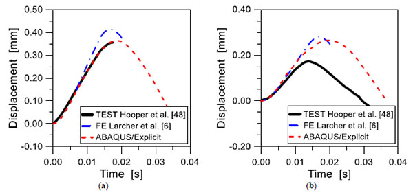
In Fig. (10a), comparisons are proposed for a 3/1.52/3 mm laminated glass panel (1.5 m × 1.2 m the nominal sizes) subjected to 12.8kg of C4-explosive (e.g. 15kg of equivalent TNT) at a distance of 10m. The glass panel was connected by means of a 6mm thick and 20mm wide silicone joint to a rigid frame. (Fig. 10b), otherwise, refers to a laminated glass specimen of identical nominal dimensions and mechanical properties, subjected to 12.8kg of C4-explosive at a distance of 13m. For FE purposes, the corresponding time-pressure waves were calculated in accordance with Section 4.2, and implemented in the corresponding ABAQUS/Explicit models in the form of impulsive distributed pressures.
As shown, close agreement was generally found between test results and corresponding FE predictions, both in terms of uncracked stiffness of the panel and (especially for (Fig. 10a) maximum deflections. Partial overestimation of maximum displacements was conversely found for (Fig. 10b), hence suggesting the rational pre-cracked FE modelling assumptions (e.g. appreciable time-displacement estimations for the initial instants of the dynamic response) but emphasizing the intrinsic possibilities and limitations of FE studies, typically related to the use of simplified layered shell models. Especially in the post-cracked phase, several aspects can markedly affect the obtained test and FE data (e.g. the possible PVB foil tearing after glass cracking, or the failure of the sealant joints along the panel’ edges, etc.).
For both the experiments of (Fig. 10) [48], for example, no tearing of PVB foils was observed after glass cracking, but a joint failure mechanism occurred along the panel’ edges (after a further glass panel rebound, in the case of (Fig. 10b)). Appropriate post-cracked FE simulations should be consequently able to take into account and properly describe a multitude of possible damage scenarios that are not fully included in the current ABAQUS/Explicit models, based on the purpose of this research project (e.g. full prevention of damage and cracking in CW units by means of the proposed VE or PL devices). As also highlighted [6, 48], apart from the mechanical and geometrical calibration of all the FE model components and the FE model assembly (e.g. composite shell elements rather than full 3D solid models, etc.), it should be noticed that large sensitivity of FE results and their agreement with the corresponding experimental data is often given by small variations in the time-pressure waves input parameters (e.g. Eq. (14)).
In order to assess the major effects of VE and PL devices on a typical CW modular unit, however, the validation of FE models collected in (Fig. 10) was considered satisfactory.
Further FE assessment was in fact successively carried out towards the design concept for the VE and PL dampers proposed in (Figs. 4 and 5). In order to verify the mechanical calibration of the VE or PL devices, preliminary FE simulations were in fact carried out in ABAQUS/Explicit on full 3D solid models representative of possible damper prototypes, with geometrical properties, assembly concept and nominal dimensions according to (Figs. 4 and 5) and Tables 1 and 2. Some results are proposed in Fig. (11).
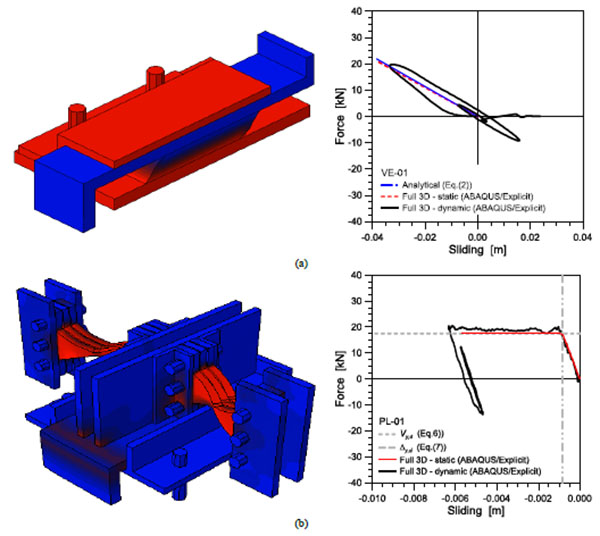
Fig. (11a), specifically, presents the expected deformed configuration for the VE-01 prototype (Table 1), under the action of external pressures acting in the direction perpendicular to the façade surface (mid-span transversal cross-section). The corresponding mechanical response is proposed in the form of shear force vs. in-plane displacements of the device, as obtained respectively from analytical calculations (Eq.(2)) and a FE nonlinear dynamic analysis of the device under an impulsive load (‘Full 3D – dynamic’). The VE device, specifically, was subjected to a pressure-time impulse according to (Fig. 8), with a positive phase duration of 0.07s, acting on the bracket end surface (e.g. to reproduce the reaction force deriving from the frame). The obtained cyclic response was then monitored in the time interval 0 ≤ t ≤ 0.2s. The elastic stiffness of the same full 3D model under linearly increasing, static shear loads is also proposed in (Fig. 11a) (‘Full 3D – static’). (Fig. 11b), similarly, refers to the mechanical response of the PL-01 damper. A distribution of Von Mises stresses in the steel components (blue-to-red contour plot) is proposed, together with a comparison of analytical (Eqs.(6)-(7)) and FE numerical calculations obtained for the full 3D model under an impulsive load (‘Full 3D – dynamic’) or static actions (‘Full 3D – static’).
As for the case of the VE-01 device, a rather close agreement was found between the discussed modelling approaches, hence suggesting the validity of the FE models implemented for the nonlinear dynamic simulations on the CW assemblies (see Section 5).
5. FE PARAMETRIC STUDY AND DISCUSSION OF RESULTS
Parametric FE results obtained by nonlinear dynamic simulations were then properly analysed, in terms of maximum effects of the assigned blast loads on the whole system dynamic behaviour as well as its key components (e.g. the glass panel, the supporting frame, the sealant joints and the additional dissipative devices), for the M01 curtain wall model and the façade modules with VE or PL devices.
In the so assembled glazed systems, for example, the silicone joints play an important role. The external loads acting on the glass surface are in fact transferred from the glass panel itself to the silicone sealant joints and hence – through the supporting frame – to the structural background. Two main components of action are activated in the sealant joints. The first one, deriving from the pressures acting on the glass surface, acts in the direction perpendicular to the panel and involves normal compressive stresses in the bead of silicone. Gaskets and steel setting blocks are often used in practice, through the thickness of sealant joints, in order to avoid crushing phenomena. The second component of stress, conversely, acts in the plane of glass and takes the form of shear stresses in the sealant joints, and thus in transversal loads in the tubular mullions. The structural integrity of glass panels, consequently, should be achieved by means of a proper design of all the CW components.
5.1. High-Level Blast Loading Scenarios
Incremental nonlinear dynamic analyses were carried out first on the M01 and VE / PL models subjected to the BLAST-150 air pressure wave of (Fig. 8). Throughout the dynamic simulations, having a total duration of 0.2s (e.g. ≈2 times the assigned pressure-time wave (Fig. 8) and ≥ 4 the fundamental period of vibration T0 of the CW modular unit), the impulsive pressure was described in the form of a uniformly distributed, impulsive load.
The main results are proposed in (Figs. 12-14) (in the time range comprised between the impact (t= 0) and t=0.1s) and Tables 3 and 4.
| Device # |
σg,max [MPa] |
Cracking [Y/N] |
σm,max / Yielding [MPa] / [Y/N] |
τjoint,max [MPa] |
Vd,max [kN] |
umax / H [-] |
sd,max / hd |
TFE ** [s] |
|---|---|---|---|---|---|---|---|---|
| M01 | 85.0 | Y | 209.7 / Y | 0.0232 | 54.4 | 0.03015 | - | 0.0511 |
| VE-01 | 58.9 | N | 194.7 / N | 0.0124 | 33.9 | 0.0131 | 2.057 | 0.0874 |
| VE-02 | 50.2 | N | 151.2 / N | 0.0079 | 26.1 | 0.0105 | 2.927* | 0.1142 |
| VE-03 | 39.3 | N | 86.65 / N | 0.0029 | 13.56 | 0.0042 | 4.518* | 0.2141 |
| Device # |
σg,max [MPa] |
Cracking [Y/N] |
σm,max / Yielding [MPa] / [Y/N] |
τjoint,max [MPa] |
umax / H [-] |
sd,max [mm] |
Vd,max [kN] |
Vd,max / Vy,d [-] |
TFE ** [s] |
|---|---|---|---|---|---|---|---|---|---|
| M01 | 85.0 | Y | 209.7 / Y | 0.0232 | 0.03015 | - | - | - | 0.0511 |
| PL-01 | 72.2 | N | 199.8 / N | 0.0134 | 0.0142 | 72.1 | 17.6 | 1.0 | 0.0511 |
| PL-02 | 53.9 | N | 136.3 / N | 0.0067 | 0.0101 | 110.6 | 10.9 | 1.0 | 0.0511 |
| PL-03 | 72.7 | N | 200.2 / Y | 0.0194 | 0.0180 | 49.9 | 22.6 | 1.0 | 0.0511 |
| PL-04 | 66.6 | N | 192.9 / N | 0.0126 | 0.0140 | 77.6 | 17.6 | 1.0 | 0.0534 |
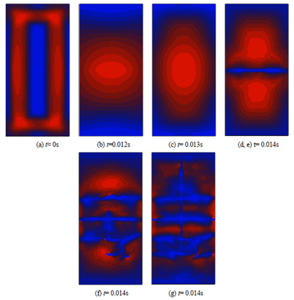
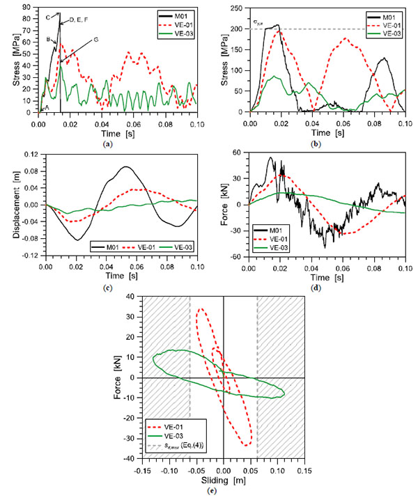
In Fig. (12), specifically, the qualitative distribution of maximum principal stresses in glass is proposed for the first instants of the CW dynamic response (maximum stresses tending from blue to red). The correspondence between these (a)-(g) contour plots is provided in (Fig. 13a). As shown, the assigned blast pressure acts as a moving, impulsive load on the glazed system. The BLAST-150 wave pressure, however, clearly involves maximum effects exceeding the M01 curtain wall capacities. The maximum principal stresses are in fact first located near the glass panel supports (e.g. the metal frame, (Fig. 12a)), but rapidly moves towards the panel centre (Fig. 12b and c), leading to the almost simultaneous failure of both the glass plies at about 0.014s (Fig. 12d-g). After glass cracking (Fig. 13a), the dynamic response of the M01 system largely modifies, being characterized by yielding of the tubular mullions (Fig. 13b), a smaller frequency of vibration of the damaged system and largest relative deflections attained in the cracked panel (Fig. 13c), while the effect of glass cracking can be noticed also in terms of distribution in time of the maximum reaction forces transmitted from the damaged CW unit to the structural background (Fig. 13d). In terms of in-plane behaviour of the sealant joints, the FE studies highlighted an almost linear elastic response under the assigned blast load, and no damage occurred in them (Table 3).
A totally different dynamic response was obtained for the same CW unit equipped by VE or PL dampers. In Figs. (13 and 14) and Tables 3 and 4, additional comparative results are in fact proposed for the M01 module towards the glazing system equipped by some of the VE or PL devices configurations collected ion (Tables 1 and 2). The maximum blast effects on the façade components (e.g. supports, bracing frame, sealant joints) are collected in the form of:
- maximum tensile stress in glass (σg,max), and possible cracking
- maximum stresses in the bracing mullions (σm,max), and possible yielding
- maximum shear stresses in the sealant joints (τjoint,max)
- reaction forces transmitted to the structural background (Vd,max). In presence of PL devices, Vd,max is also compared with the yielding force Vy,d of the proposed ADAS dampers (Eq.(6))
- deformation ratio umax/H, defined as the maximum relative deflection at the centre of the glass panel, as a function of the panel height H
- deformation ratio sd,max/hd, signifying the maximum shear strain γ in the VE compound (Fig. 3)
- fundamental period of vibration TFE of the curtain wall modular unit, as obtained from FE simulations and also in accordance with Eq.(11)
The main advantage of VE devices, as also in agreement with past investigations discussed [15], is given by a double beneficial contribution represented by the additional flexibility they introduce at the support points, as well as their significant damping capacity (Eq.(1)). As far as the stiffness of VE devices decreases, specifically, their damping effect increases and an important reduction of maximum stresses in the whole façade components is expected. On the other hand, careful consideration should be paid in the estimation of the optimal VE key parameters, since a high flexibility would also result in maximum deformations of the VE compound leading the device to failure (Table 3). For the CW object of study, in particular, an interesting beneficial effect was obtained with the VE-01 solution (Table 3), while the VE-02 and VE-03 proposals typically resulted in important mitigation effects, but maximum deformations in the VE layer progressively leading the same VE dampers to failure (Fig. 13e).
Interesting structural effects in the CW components were obtained also in presence of PL devices (Fig. 14 and Table 4). In this latter case, however, particular attention should be dedicated in the design of two key parameters, represented by the elastic stiffness kd and the shear resistance/sliding force Vy,d.
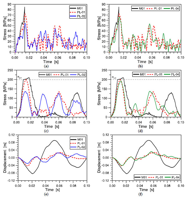
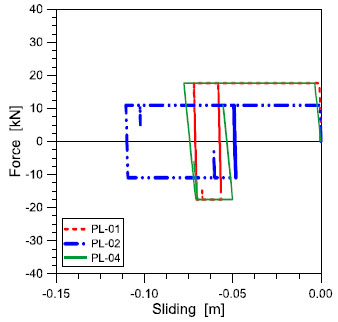
In order to highlight the effects of both PL stiffness and resistance parameters, in accordance with Table 2, (Fig. 14) shows in fact the different effects obtained in the CW assembly by means of PL devices characterized by variable stiffness kd (Fig. 14a,c,e) or variable shear resistance Vy,d (Fig. 14b,d,f) respectively, together with the cyclic response of the three examined PL configurations (Fig. 15). Comparisons are proposed in terms of maximum (i) principal stresses in glass, (ii) stresses in the tubular mullions, (iii) relative deflections at the centre of the panel.
As also highlighted in (Table 4), the performed FE studies generally emphasized that ADAS devices can provide beneficial structural effects on the examined CW unit under the BLAST-150 wave pressures.
As in presence of VE devices, due to deformations of the ADAS themselves, the maximum relative deflections in the glass panel are almost half the M01 reference configuration (Fig. 14e and f) and yielding of the tubular mullion is preserved (Fig. 14c and d). In terms of maximum stresses in glass (Fig. 14a and b), the application of PL dampers generally avoided the failure of glass plies, for all the studied configurations. While the maximum stresses in glass resulted almost independent on the ADAS elastic stiffness kd (Fig. 14a and b and Table 4), however, FE comparisons highlighted the importance of a proper calibration of the shear resistance Vy,d of the same dampers. The design of ADAS devices with high shear resistance Vy,d, compared to the incoming reaction forces, would in fact result in PL dampers behaving as fully rigid restraints, hence leading to maximum stresses in glass almost comparable with the M01 reference configuration.
5.2. Medium/Low Level Blast Loading Scenarios
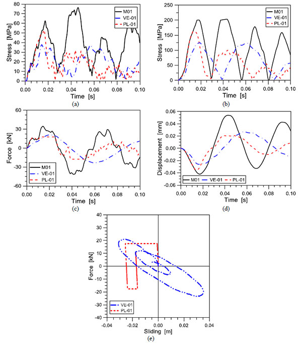
Final preliminary assessment of the proposed VE and PL devices was made by taking into account impulsive pressures of low/medium intensity. Parametric results obtained for the M01, VE-01 and PL-01 systems under the BLAST-75 pressure wave are compared in (Fig. 16), in the form of maximum principal stresses in glass (Fig. 16a), maximum stresses in the tubular mullions (Fig. 16b), reaction forces transmitted to the structural background (Fig. 16c) and relative displacements at the centre of the panel (Fig. 16d).
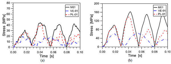
Additional comparative calculations are also collected in (Fig. 17), for the same glazing assemblies subjected to the BLAST-75 pressure-time wave, while Table 5 summarizes the main outcomes of BLAST-75 and BLAST-25 loading scenarios.
| Blast load | Device # |
σg,max [MPa] |
Cracking [Y/N] |
σm,max ; Yielding [MPa] ; [Y/N] |
Vd,max [kN] |
umax / H [-] |
sd,max [mm] |
|---|---|---|---|---|---|---|---|
| BLAST-75 | M01 | 76.4 | N | 203.5 ; Y | 34.6 | 0.0180 | - |
| VE-01 | 37.7 | N | 124.8 ; N | 21.1 | 0.0090 | 35.3 | |
| PL-01 | 52.9 | N | 161.9 ; N | 17.6 ** | 0.0118 | 25.6 | |
| BLAST-25 | M01 | 44.4 | N | 162.3 ; N | 24.3 | 0.0110 | - |
| VE-01 | 19.3 | N | 64.14 ; N | 9.9 | 0.0048 | 14.1 | |
| PL-01 | 40.74 | N | 137.35 ; N | 17.6 ** | 0.0067 | 13.1 |
As expected, as far as the blast wave intensity decreases, the effectiveness of PL-01 dampers vanishes, compared to VE-01 devices, due to the intrinsic mechanical behaviour of VE and PL dampers respectively (Section 3). While VE dampers provide additional damping capacities under dynamic loads affecting the CW unit, independently on their amount, the activation of PL dampers strictly depends on their shear resistance Vy,d. As a result, it can be seen that although the M01 curtain wall modular unit behaves fully elastically under the assigned BLAST-75 and BLAST-25 pressure waves (e.g. fully undamaged glass panels and tubular mullions), the investigated VE-01 and (partially) PL-01 dampers can in any case improve the CW dynamic response, compared to the reference M01 system.
In conclusion, it is clear that the design and optimization of VE or PL dampers should be properly calibrated, based on the CW mechanical properties and the expected loading scenarios. The presented FE parametric studies, however, emphasized the feasibility and potentiality of the proposed passive control system applications, hence suggesting further research developments and detailed validations.
SUMMARY AND CONCLUSION
In this paper, the behaviour of a conventional glazing curtain wall subjected to air blast loads has been investigated by means of Finite-Element numerical simulations. The structural efficiency, criticalities and feasibility of two different typologies of dissipative devices introduced at the point of supports of each curtain wall modular unit have been assessed. In the first case, visco-ealstic (VE) solid dampers have been proposed.
The use of the proposed VE devices, as shown, involves interesting benefits in the global behaviour of the curtain wall, since they cut down the maximum stresses in the glass lites, as well as in the silicone joint and in mullions, reducing their deflection and the maximum reactions transmitted to the structural backup. The main advantage of these devices consists of the introduction of additional deformability in the conventional curtain wall. In addition, they dissipate a part of the incoming energy due to explosion, preventing such brittle structures from serious damage and hence possible injures. As shown, the structural effectiveness of appropriately-dimensioned VE devices guarantees satisfactory levels of dynamic performances for similar curtain walls in the presence of high-level air blast loading as well as in presence of low-level explosions or ordinary dynamic loads (traffic vibrations, wind, etc.). Their effectiveness is strictly dependent on the flexibility of the VE compound. Careful consideration, however, should be paid in their optimal design, in order to avoid large strains in the VE layer leading the device to failure.
In the second case, elasto-plastic (e.g. ADAS) devices have been examined. The implicit advantage of this device typology – compared to VE solutions – is given by a stable mechanical behaviour (e.g. independency on the operational frequency and temperature conditions). Conversely, being the key input parameters of ADAS dampers represented by the elastic stiffness and shear resistance, their components should be properly designed, so that an appropriate flexibility and strength could be ensured at the curtain wall supports, under impact loads and dynamic pressures of variable intensity. Compared to VE devices – typically characterized by activation under dynamic loads of variable intensity – PL dampers can exploit their effectiveness under specific loading ratios only, hence behaving as fully rigid supports under external loads not exceeding the PL shear resistance. In any case, both the examined solutions highlighted important benefits for application in glazing structural systems, hence suggesting further detailed experimental validation and full 3D investigations for the development of design rules and recommendations of practical use.
CONFLICT OF INTEREST
The authors confirm that this article content has no conflict of interest.
ACKNOWLEDGEMENTS
Declared none.

