1. INTRODUCTION
Lightness of thin-walled beams is one of the reasons for their high performance. These beams are widely used in structures and aerospace industries. If the cross section of the thin-walled beams is mono- symmetric or asymmetric, the center of mass and the center of shear will not fit in each other. This causes a relative complexity in the behavior of these beams. Because in such a case, the bending and torsion modes are coupled and ultimately make it difficult to precisely predict the dynamic characteristics of these beams. One of the most powerful tools for solving such problems is the use of the dynamic stiffness matrix method. This method has advantages over finite element method. In the finite element method, the characteristics of an element is extracted using assumed shape functions for that element, so they are not exact. In dynamic stiffness matrix method, the dynamic characteristics are obtained from the analytical solution of the governing differential equations, so we can say that they are exact. Over the last few years, many studies have been performed in the field of formulation of dynamic stiffness matrix (DSM) of beams. The dynamic stiffness matrix of a Timoshenko beam was investigated by Cheng [1] for the first time. Williams and Howson [2] considered the effect of axial load on the natural frequencies of Timoshenko beam. Banerjee [3] studied a beam with a section having one axis of symmetry and derived some explicit terms for the stiffness matrix arrays regardless of axial load effect. Banerjee and Williams [4] investigated dynamic stiffness matrix for coupled flexural-torsional vibration of Timoshenko beam. Banerjee et al. [5] studied warping effect on the formulation of dynamic stiffness matrix. Bercin and Tanaka [6] surveyed coupled flexural-torsional vibrations of uniform beam having single symmetric section, considering conventional support conditions. Li Jun et al. [7] derived the free vibrations of thin-walled Timoshenko beam under axial load, in which the effects of axial load, warping stiffness, shear deformation, and rotational inertia were taken into consideration and it was used from continuous model. Rafezy and Howson [8] derived the dynamic stiffness matrix of a three-dimensional (3D) shear-torsion beam with an asymmetric cross-section. The beam had the unusual theoretical property, so that, it allowed only for shear deformation but not bending deformation. Ghandi et al. [9] replaced Euler-Bernoulli theory with Timoshenko theory when the external layer of thin-walled beam is modeled and they assumed that the thin-walled part of the beam could have either open or closed section shape and would create flexural, shear, warping and Saint- Venant rigidities. Ghandi et al. [10] also derived the dynamic stiffness matrix of uniform beam with asymmetric cross section and elastic support under axial load. The mentioned beam consisted of an external enclosed thin-walled layer that was combined with a shear resistant filled core. Ghandi and Shiri [11] investigated the effect of the eccentricity of axial load on the natural frequencies of asymmetric thin-walled beams using exact dynamic stiffness matrix method.
Many researches have been performed in the field of the response of beams with symmetric cross-section subjected to deterministic and random dynamic loads. Eslimi-esfahani et al. [12] analytically investigated the dynamic response of beam with coupled flexural-torsional vibration subjected to deterministic and stochastic dynamic loads for the first time. In another study, Eslimy-Isfahany and Banerjee [13] analytically calculated dynamic response of beam with constant axial load with coupled flexural-torsional vibration under definitive and stochastic dynamic loads by using modal analysis method. Li Jun et al. [14] derived an explicit term for dynamic response of single symmetric Timoshenko beam subjected to stochastic excitations. Following the previous work, Li Jun et al. [15] derived the effects of axial load by the calculation of dynamic response of single symmetric Timoshenko beam against stochastic excitations.
In most of these researches, cross-section of the beam was mono-symmetric and Euler-Bernouli theory was used to model bending of beam. Moreover, to model beam bending, Euler-Bernouli theory is not capable of providing correct results when beams with large sections compared to their lengths or extraction of natural frequencies of higher modes are under study. In such conditions, Timoshenko beam theory in which, shear deformation and rotary inertia parameters are considered, should be employed. In this paper, considering the effect of definitive dynamic load, the analytical dynamic response of 3D flexural-torsional beam with asymmetric cross-section will be investigated by the help of exact dynamic stiffness matrix and modal analysis methods.
2. THEORY
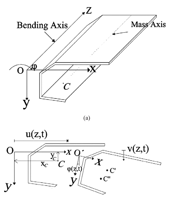
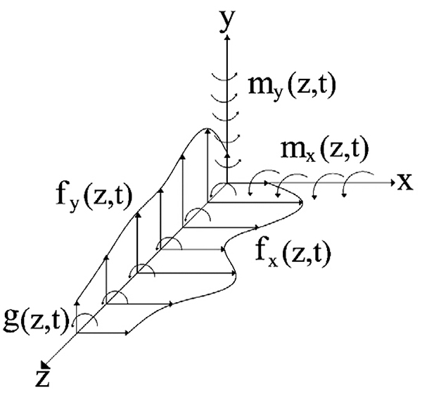
The cross-section of the intended beam is shown in Fig. (1). This beam is a uniform 3D beam with asymmetric cross-section. The Timoshenko beam theory is used for modeling the bending beam. This beam has flexural rigidities of EIx and EIy in x - z and y - z planes, torsional warping rigidity of EIω, torsional Saint- Venant rigidity of GtJt and shear rigidities of GtAxt and GtAyt, where Gt is the shear modulus, Jt is the section torsional constant, Axt and Ayt are equivalent shear section in x and y directions, respectively. In Fig. (1), the center of gravity is denoted by C, and shear center is shown by O. The axes crossing the center of gravity and shear center are known as mass axis and bending axis, respectively. The origin of the coordinate system, is placed at O, x and y axes are in the direction of main axes of the cross-section and z axis coincides with the bending axis. The location of the point C in the co-ordinate system Oxy is given by (xc, yc). The beam total mass is distributed along its length as uniform distributed load and m is the beam mass per unit length. The flexural translation in the x and y directions and torsional rotation about the z-axis are represented by u (z, t), v(z, t) and φ(z, t), respectively. During the translation phase u(z, t) and v(z, t)) the shear center moves to O´ and the mass center C moves to C´. During the rotation phase (φ(Z, t)), the mass center moves additionally from C´ to C˝. The external loads applied on the thin-walled beam include unit length forces fx (z, t) and fy (z, t), which are applied on the bending axis in the directions of x and y axes, respectively, unit length bending moment mx (z, t) in the x - z plane around y axis, unit length bending moment mx(z,t) in the x-z plane around y axis and also unit length torsion moment g (z, t) that is applied around the bending axis (Fig. 2).
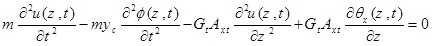
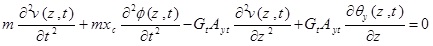
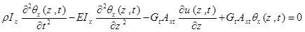
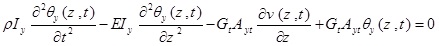
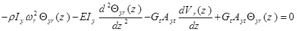
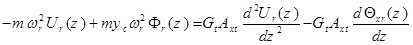
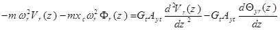
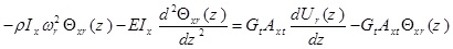
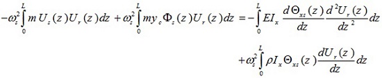
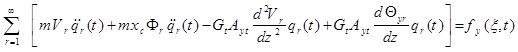
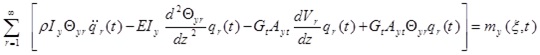
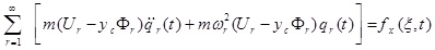
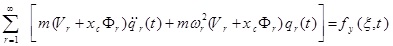
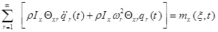
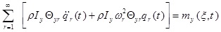
The differential equations governing the beam moment are as five coupled partial differential equations that are defined bellow using Hamilton’s principle:
 |
(1a) |
 |
(1b) |
 |
(1c) |
 |
(1d) |
 |
(1e) |
where θx (Z, t) and θy (Z, t) are the rotation of the cross-section due to bending in the x-z and y–z planes, respectively. p, is the material density of the thin-walled beam.
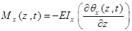
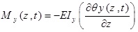
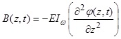
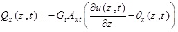
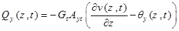
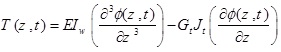
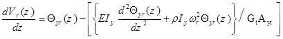
Also by using Hamilton’s principle, the expressions for shear forces Qx (z, t) and Qy (z, t), bending moments Mx (z, t) and My (z, t), torsional moment T(z, t) and Bi-moment B(z, t) can be obtained as follows:
 |
(2a) |
 |
(2b) |
 |
(2c) |
 |
(2d) |
 |
(2e) |
 |
(2f) |
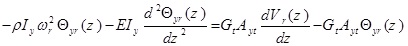
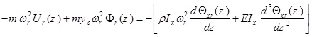
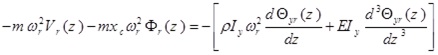
3. FREE VIBRATION ANALYSIS
In order to determine natural frequencies and vibration modes, it is required to perform the undamped free vibration analysis of the system. For this purpose, the external applying forces are considered equal to zero and thus, the above equations could be written as follows
 |
(3a) |
 |
(3b) |
 |
(3c) |
 |
(3d) |
 |
(3e) |
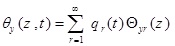
In order to analyze the free vibration, the answers of u (z, t), v (z, t) θ (z, t), and θ (z, t) are written as follows
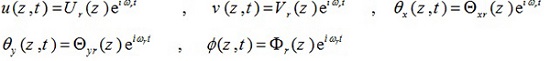 |
(4) |
In the above relations, r = 1,2,3... represents the vibrational mode number.
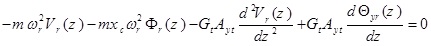
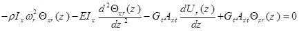
Substituting equation (4) into equation (3), gives
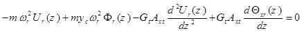 |
(5a) |
 |
(5b) |
 |
(5c) |
 |
(5d) |
 |
(5e) |
By applying the dynamic stiffness matrix method on the above governing differential equations, we can obtain the natural frequencies and mode shapes. For this purpose, [9-11] references can be seen.
Equations (5a- d) can be rewritten as follows:
 |
(6a) |
 |
(6b) |
 |
(6c) |
 |
(6d) |
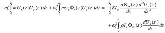
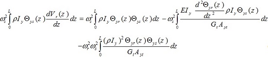
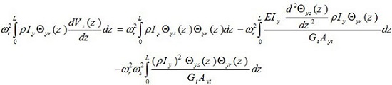
4. EXTRACTION OF THE ORTHOGONALITY PROPERTIES
The most significant property of the mode shapes is that they form a set of orthogonal mathematical functions. To analyze the forced vibrations, the orthogonality condition would have to be used. The orthogonality conditions are applied to any two different modes, they cannot be applied to two modes having the same frequency. For discrete systems, the orthogonality conditions are available in all references related to the dynamics of structures. The studied beam in this paper is a distributed properties system. The vibration mode shapes derived for beams with distributed properties have orthogonality relationships equivalent to those for the discrete parameter systems. Orthogonality conditions for three-dimensional asymmetric thin-walled Timoshenko beam is derived in this paper as follows:
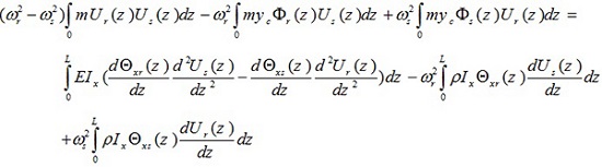
Substituting equation (6c) into (6a) and also equation (6d) into (6b) gives
 |
(7a) |
 |
(7b) |
Multiplying (7a) by Us (z) (sth vibrational mode) and integrating with respect to Z gives
 |
(8) |
If the last integration in this equation is performed by parts, it is found to give
 |
(9) |
The integrated term is nil because from equations (6c) and (2d), it can be seen that the contents of the square brackets are equal to the shear force which vanishes at the boundaries z = 0 and z = L at a free end. Also at a fixed end, simply supporting the end value of U (z), it is equal to zero and then the above integrated term is nil.
 |
(10) |
Following this, again the integrated term vanishes since the bracketed term is equal to bending moment which is zero at the extremities, so finally the equation (8) is expressed as follows:
 |
(11) |
Similarly, the solving stages begin with equation (7a) rewritten for the sth mode and multiplied throughout by Ur (z) (rth vibrational mode), and by following the same steps it gives,
 |
(12) |
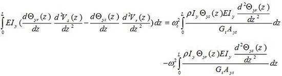
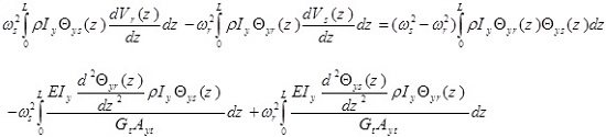
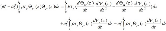
If the last two equations are subtracted, it can now be observed that
 |
(13) |
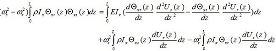
By performing the similar operation for equation (7b), the following result is finally obtained
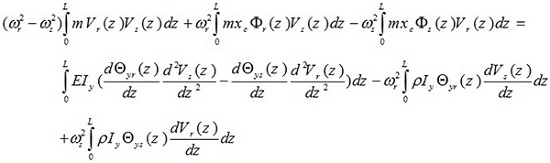 |
(14) |
By dividing equation (6c) to GtAxt and (6d) to GtAyt find that
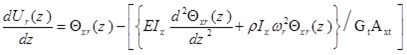 |
(15a) |
 |
(15b) |
When equation (15a) is differentiated with respect to z, multiplied by  and then integrated with respect to z, finally it gives
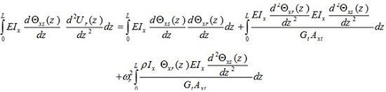 |
(16) |
When the suffices r and s in this last equation are interchanged, it is found that
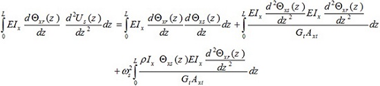 |
(17) |
By subtracting equation (16) from (17), the following relation is obtained.
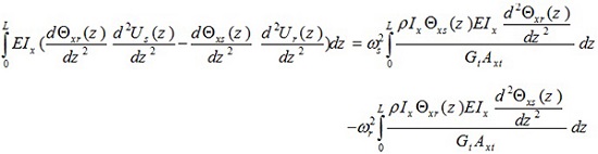 |
(18) |
By performing the similar operation for equation (15b), the following result is finally obtained
 |
(19) |
Multiplying equation (15a) throughout by
 and integrating with respect to z, give,
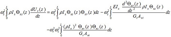 |
(20) |
Interchanging r and s gives:
 |
(21) |
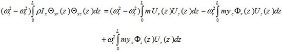
When these last two equations are subtracted, they give
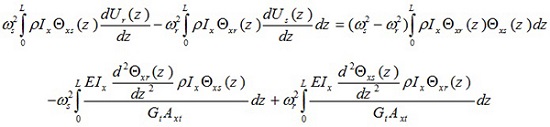 |
(22) |
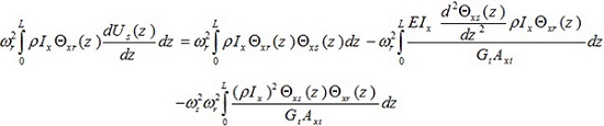
Multiplying equation (15b) throughout by
and integrating with respect to z, give:
 |
(23) |
When the suffices r and s in this last equation are interchanged, the equation becomes
 |
(24) |
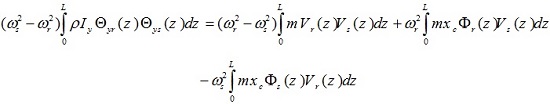
Subtraction now reveals that,
 |
(25) |
If equation (18) and (22) are now added together, they give
 |
(26) |
Also if equations (19) and (25) are now added together, they give
 |
(27) |
Comparison of equation (26) with that of equation (13) reveals that
 |
(28) |
Also the comparison of equation (27) with (14) gives
 |
(29) |
In this step, equation (5e) is written for the rth and sth modes; these are multiplied throughout by Фs (Z) and Фr (Z) integrated with respect to z. Finally it gives
 |
(30) |
Equations (28), (29) and (30) may be added together to give
 |
(31) |
In the above equation, if r = s, then the following equation is obtained.
 |
(32) |
The above relation is satisfied because, (ω2r-ω2r) = 0, so the result of the integral is a constant value as follows,
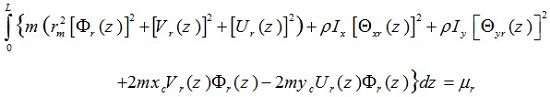 |
(33) |
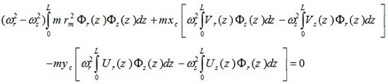
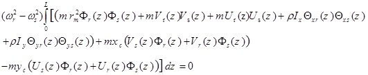
For r ≠ s, so that (ω2r-ω2r) ≠ 0 therefore, to derive equation (31), we must have the following relation:
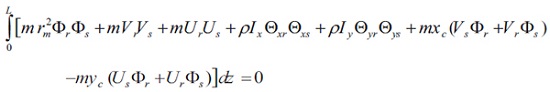 |
(34) |
Equations (33) and (34) can be shown as the following general form
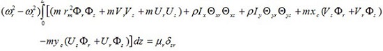 |
(35) |
The above equation shows the orthogonality condition for different mode shapes of the thin-walled Timoshenko beams with asymmetric cross-section. µ is the generalized mass in the rth mode, and δsr the Kronecker delta function defined as follows:
 |
(36) |
With the free vibration natural frequencies, mode shapes and orthogonality condition described above, we can calculate dynamic response of the Timoshenko thin-walled beam under deterministic loads.
5. DYNAMIC RESPONSE ANALYTICAL CALCULATION
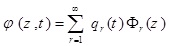
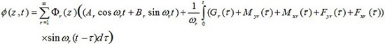
Now, the partial differential equations (1) are taken into consideration that are required to be solved for the applied external forces of fx (z, t), fy (z, t), mx (z, t), my (z, t), and g (z, t). Assuming that the eigenvalue problem is solved for extracting natural frequencies and modes, the response against the applied loads is obtained from the linear combination of the modes as follows:
 |
(37a) |
 |
(37b) |
 |
(37c) |
 |
(37d) |
 |
(37e) |
In the above equations, qr (t) is the modal coordinate (time coordinate) of the rth mode. As a result, the responses u (z, t), v (z, t), θx (z, t), θy (z, t) and ϕx (z, t) are defined as the total participation effects of each mode. The rth term in the series of equation (37) represents the participation rate of the rth mode.
Substituting equations (37) into equations (1) and the introduction of the non-dimensional variable
 then yields
 |
(38a) |
 |
(38b) |
 |
(38c) |
 |
(38d) |
 |
(38e) |
Substituting equations (5) into equations (38) gives:
 |
(39a) |
 |
(39b) |
 |
(39c) |
 |
(39d) |
 |
(39e) |
In this step, each sentence of (39a) in Us , each sentence of (39b) in Vs, each sentence of (39c) in Θxs, each sentence of (39d) in Θys and each sentence of (39e) are multiplied by Фs and integrated throughout the beam. After adding the obtained equations, the equation becomes
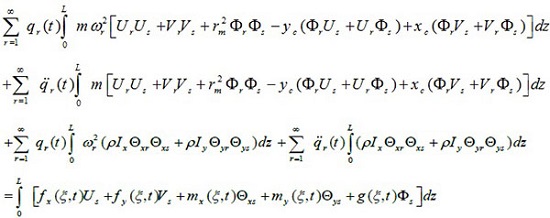 |
(40) |
The above equation is as follows after simplifying and changing the order of integral and sign

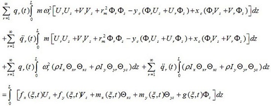 |
(41) |
Regarding the property of the orthogonality of modes given in (35), it was observed that for all values of r ≠ s, the value of the two integrals on the left of the above equation is eliminated, only for r = s the following equation will remain:
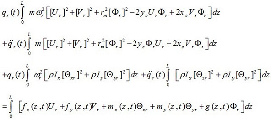 |
(42) |
The above equation can be expressed in the following form
 |
(43) |
By introducing the following parameters,
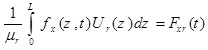 |
(44a) |
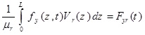 |
(44b) |
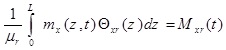 |
(44c) |
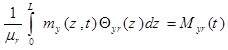 |
(44d) |
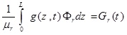 |
(44e) |
Now, equation (43) is rewritten as follows
 |
(45) |
Therefore, there are an infinite number of equations similar to equation (45) and one equation for each mode. The partial differential equation (1) for unknown functions u (z, t), v (z, t) θx (z, t) θy (z, t) and Ф (z, t) are transferred into an infinite set of ordinary differential equations (45) in terms of qr(t) unknowns.
For the applied dynamic loads of fx (z, t), fy (z, t), mx (z, t), my (z, t) and g(z, t) the unknown system functions u (z, t), v (z, t), θx (z, t), θy (z, t) and ϕ (z, t) could be determined by solving the modal equations in terms of qr (t). The equation of each mode is independent to the other modes; thus, it could be solved separately. For solving equation (45), which is similar to the form of movement equation for single degree of freedom (SDOF) system, Duhamel's integral is used. Therefore, the answer of equation (45) is defined as:
 |
(46) |
After determining and qr (t), by using equations (37) and (46), system response to arbitrary dynamic forces fx (z, t), fy (z, t), mx (z, t), my (z, t) and g (z, t) is as follows
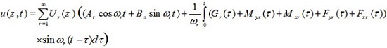 |
(47a) |
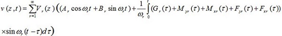 |
(47b) |
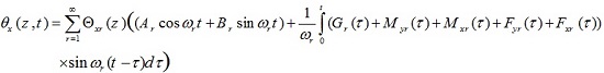 |
(47c) |
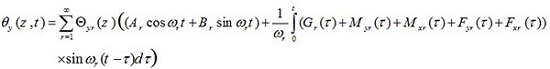 |
(47d) |
 |
(47e) |
The obtained responses can be used for any arbitrary deterministic loading. In the following, the response against deterministic harmonic load is calculated using equations (47) for instance.
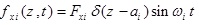
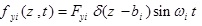
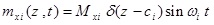
In this part, it was assumed that the centralized harmonic forces having Fxi amplitudes are applied in the direction of x axis in the points Zi = ai the forces with Fyi amplitudes are applied in the direction of y axis in the points Zi = bi, bending moments having Mxi amplitudes are applied in x-z plane around y axis and in the points Zi = Ci, bending moments with Myi amplitudes are applied in y-z plane around x axis and in the points Zi = di, and torsional moments with Gi amplitudes are applied around z axis and in the points Zi = ei, where i = 1,2,3,.....,N.
The mentioned applied loads are defined as follows:
 |
(48a) |
 |
(48b) |
 |
(48c) |
 |
(48d) |
 |
(48e) |
where, ωi is the rotational frequency of the applied loads.
In this state, by using equations (44), the generalized loads functions become,
 |
(49a) |
 |
(49b) |
 |
(49c) |
 |
(49d) |
 |
(49e) |
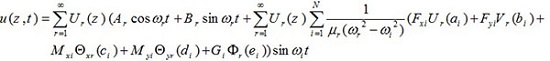
Finally, the response of u (z, t), v (z, t), θx (z, t), θy (z, t) and ϕ(z, t) to assumed applying loads is as follows
 |
(50a) |
 |
(50b) |
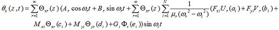 |
(50c) |
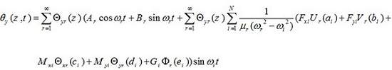 |
(50d) |
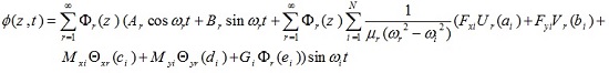 |
(50e) |
6. NUMERICAL RESULTS
The following example is presented in order to validate the formulation proposed in the present paper.
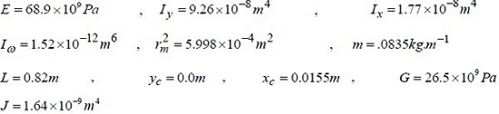
In this example, a thin-walled cantilever beam having semicircular section with one axis of symmetry is investigated. The physical and geometrical specifications of the studied section are as follows (Fig. 3):
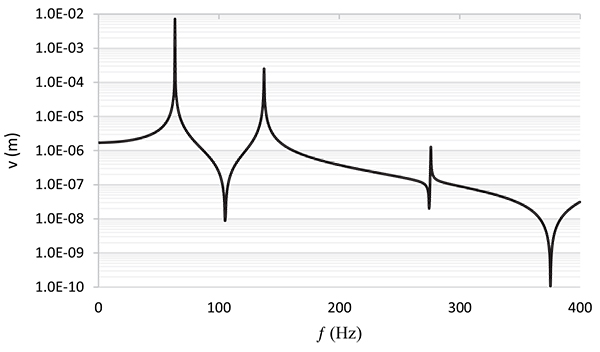
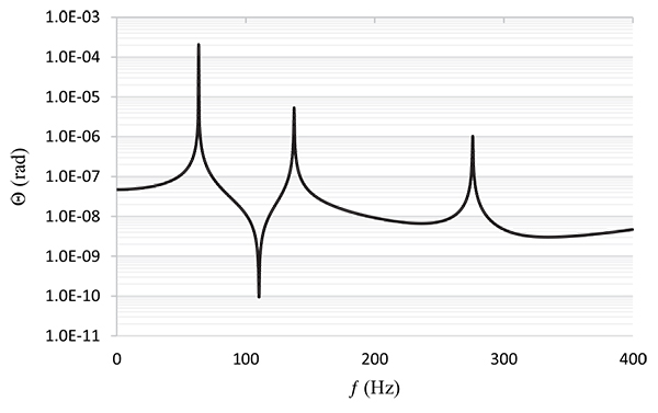
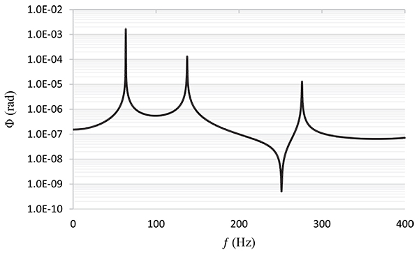
In this example, it was assumed that unit harmonic forces with unit amplitude are applied to the tip of the cantilever beam and the transitional bending displacement, rotational and torsional angles were calculated at the cantilever beam tip under the applied harmonic load with different frequencies. For calculating the response, the first five modes of vibration were used. Therefore, the first five bending–torsion coupled natural frequencies and vibrating modes were first calculated with the help of the dynamic stiffness matrix. The calculated natural frequencies are presented in Table 1.
Then, for each mode, the values of µ were calcluted. For the first five modes, the µ as follows:
By using equations (50) and considering Fx = 0, Mx = 0, G = 0 and Fy = 1 as well as the location of the point, b = 0.82m, the intended responses were calculated at the cantilever edge point and plotted in the semi-logarithmic diagrams of Figs. (4, 5, and 6). In the mentioned figures, the absolute magnitudes of the obtained values were considered on the vertical axis, which is a logarithmic axis.
CONCLUSION
In the present study, an analytical method is proposed for determining the dynamic response of asymmetric thin-walled beams subjected to different types of centralized and distributed definitive dynamic loads. In order to solve vibration problems, the study used accurate dynamic stiffness matrix. Since the dynamic stiffness matrix is derived from analytical solution of the differential equations of movement, it makes it possible to calculate natural frequencies and vibrating modes accurately and without any loss in the precision. The natural frequencies and mode shapes were obtained by using Wittrick–Williams algorithm.
Due to the general shape of the beam (i.e. a perfect asymmetric section), the mass and shear centers were not coincident and thus, flexural and torsional vibrations were observed to be dependent on each other. Accordingly, determining the analytical response of the 3D thin-walled beam with asymmetric section against dynamic deterministic loads is considered as a very complicated problem. Using the introduced dynamic stiffness matrix in combination with modal analysis method, this complexity can be addressed.
By using the formulation presented in this paper, the dynamic response of members with arbitrary asymmetric section can be derived also with different boundary conditions under any arbitrary applied definitive dynamic loading at various points.
CONSENT FOR PUBLICATION
Not applicable.
CONFLICT OF INTEREST
The authors declare no conflict of interest, financial or otherwise.
ACKNOWLEDGEMENTS
Declared none.