All published articles of this journal are available on ScienceDirect.
Experimental and Numerical Analyses of Steel-concrete Composite Floors
Abstract
Background:
The performances of composite steel-concrete slabs are strongly influenced by the connection between the concrete and the steel decking, which is essentially assured by bonding, interlocking, and adhesion. The connection can be continuous or localized by means of connectors. In order to increase the bonding between steel and concrete elements and to allow their collaboration, typically, a continuous connection with indentations or embossings is realized.
Objective:
In this study, the simulation of the concrete-steel bond interaction of a typical composite decking is analyzed. In particular, the objective is the investigation of the role of the main geometric parameters of the indentations or embossings that determine the effective functionality of the connection.
Methods:
To this scope, the results of four-point bending tests on five specimens of a typical layout of a composite floor are reported and discussed. Then, the obtained results are used to determine the shear bond strength according to the partial interaction method, by following the procedure provided by the Eurocode 4. Successively, the experimental results are exploited in order to calibrate a FE model in Abaqus software to be able to account for the basic effects involved in the shear bonding mechanism, i.e. interlocking, friction, and adhesion.
Results & Conclusion:
Finally, the obtained results are discussed, and the FE model is used to evaluate the geometrical and mechanical parameters influencing the longitudinal shear bonding resistance.
1. INTRODUCTION
Composite deck slab floors are widely adopted in many countries as they lend themselves to faster, lighter, and economical construction in buildings [1-14]. Consequently, since their introduction, a high proportion of steel structures are designed compositely. Within the USA, the first use of concrete-encased beams was on a bridge in Iowa and a building in Pittsburgh in 1894. Composite beams were first tested in Canada at the Dominion Bridge Works in 1922. Welded shear studs were first tested at the University of Illinois in 1954, which led to the publication of a design formula in 1956 and the first use of shear studs in bridges and building projects in the same year. Metal decks first appeared in the 1950s, with the first recorded use of deck stud welding on the Federal Court House in Brooklyn in 1960. It was not until 1978, however, that this arrangement was recognized in the AISC specification. Within Europe, parallel developments had been taking place, in fact, in 1950, a “Provisional Regulations for the Design of Girders in Composite Construction” was published. The British researchers Chapman & Johnson mentioned a research project in progress and buildings under construction that had been designed compositely at City University London, Imperial College London, and Cambridge University. The early UK composite bridge applications and background studies for buildings have appeared in the late 1950s [15]. The conventional jack arch flooring system was first established in the UK at the end of the 1990s and was extensively used in industrial buildings. In contrast, a new type of composite system which is used in steel frame building construction is the Steel-Concrete Composite (SCC) beam, which behaves better than the jack arch slab for the seismic loads. Composite beams are defined as “elements resisting only flexure and shear that comprise two longitudinal components connected together either continuously or by a series of discrete connectors” [16].
In steel-concrete composite structures, it is typical to adopt thin-walled steel elements to realize the floor. In fact, in a composite building, the most usual type of floor is realized with a profiled steel sheeting finished with cast-in-situ concrete, a steel mesh and, eventually, steel rebars, leaning on a grid of steel beams (referred as primary beams if connecting the columns or secondary if connecting relatively the primary beams). The steel-concrete composite slab is, therefore, composed of a profiled steel sheeting and a concrete slab. It constitutes the floor only when the composite slab is not connected to the underlying beam. Conversely, it may also be used to improve stiffness and strength of the steel members, taking advantage of the composite action, when the floor is mechanically fastened to the steel beams (e.g. with studs or other devices). The role of the steel decking is twofold. Initially, in the construction phase, it allows to cast concrete directly on site (without propping or with a limited number of supports) and, basically, it works as a formwork. Therefore, it is normally realized starting from a flat coil that is profiled to provide to the steel section, stiffness and resistance adequate to support the construction loads with a limited deflection (e.g. the concrete and/or the machinery weight). Subsequently, after that concrete is completely cured (conventionally after 28 days), concrete and steel realize a monolithic cross-section, in which the connection between profiled steel sheeting and concrete is assured mainly by adhesion or friction. In this second phase, the steel sheeting acts as a tension reinforcement for a sagging bending moment. The only additional steel that is needed in practice is normally provided to take care of shrinkage, to limit cracking, for temperature effects, and, in case of continuous slabs, it has to be provided to resist hogging bending moments.
The design of steel-concrete composite slabs is related to the definition of: nominal strengths for bending, vertical shear, and longitudinal shear resistances. The determination of the bending and vertical shear resistances follows the same specifications of reinforced-concrete members, these are based on the full interaction between the steel plate and the concrete slab assuming the steel plate as reinforcing bars of reinforced-concrete members. Conversely, the evaluation of the longitudinal shear resistance needs to consider the degree of interaction (or partial-interaction) between the steel plate and the concrete slab. However, the longitudinal shear resistance influences the structural performance, strength, stiffness, and failure mode. Therefore, it is important to exactly evaluate the longitudinal shear resistance of steel-concrete composite slab [17].
As mentioned before, the performances of the composite steel-concrete decking floor are strongly influenced by the connection between the concrete slab and the steel sheet, which is essentially assured by steel-concrete adhesion and by the mesh of the concrete on the indentations made on the steel sheet. The connection of the steel-concrete interface, made by means of connectors [18], can be continuous or localized at the end of the slab [16]. In particular, in the case of continuous connections, three different solutions are possible.
• Mechanical meshing with indentations or embossings in order to increase bonding between steel and concrete elements and to allow their collaboration.
• Frictional meshing with particular shapes of the sheeting, such as recessed corners, which, under load, determine normal mutual stresses that guarantee the friction between the concrete and the sheet.
• Adhesive connection by means of steel mesh welded to the extrados of the sheet.
In practice, in case of mechanical interlock, the design slip resistance at the steel-concrete interface evaluated with reference to the adopted sheet and determined by means of experimental tests has to be provided by the manufacturer. In particular, the check for longitudinal shear is typical of composite cross-sections. Due to the variability of the typologies of profiled steel decking, normally, it is not possible to characterize this resistance with simple and reliable equations and design assisted by testing procedures are needed. This means that for any typology of steel decking, it is normally needed to carry out specific laboratory tests on the composite floor under bending loading conditions to determine the longitudinal shear resistance.
The determination of the longitudinal shear strength is possible by means of two methods currently available in EC4: the m-k method and the partial interaction method [19, 20]. The first is based on the test data, which are used to determine a correlation between transverse shear (in this procedure, the longitudinal shear check is transformed into an equivalent transverse shear check) and the geometrical properties of the steel decking. The second is based on physical modeling of the concrete-steel connection. While the peculiarity of the first modeling approach is the simplicity, the main advantage of the second methodology is the possibility to adopt a modeling approach which is consistent with the mechanical response of the composite floor. Nevertheless, while on the one hand, the partial interaction method is more accurate in providing a physically consistent interpretation of the interaction phenomena, on the other, it has the main drawback to lead to a formulation in which the bending resistance of the composite floor at any cross-section depends on the distance of considered section from the closest support. This obviously results in more onerous and less practical calculations.
In this work, experimental flexural tests have been performed in order to evaluate the shear resistance at the steel sheet-concrete slab interface [21-26]. Subsequently, with reference to the continuous and mechanical meshing, a preliminary investigation of the role of the main geometric parameters of the indentations or embossings that determine the effective functionality of the connection at concrete slab to steel sheet interface has been assessed by means of a FE model, calibrated by means of experimental results. To this scope, the finite element software package ABAQUS [27], which has been widely used in the past for the analysis of composite elements [28-34], has been chosen for performing numerical investigation.
2. MATERIALS AND METHODS
The experimental investigation described in the following is devoted to the determination of the unitary sliding stress Tu,Rd of a composite steel-concrete [35-43] slab realized by means of “H55” corrugated steel panels with a height of 55 mm, a width of 645mm, and a nominal thickness of 0.8 mm (8/10), with a final concrete casting.
Two different sets of specimens have been developed:
Set 1: TEST L3200 - 3 slim composite slabs with a length of 3200 mm labeled H55-L3200. The three experimental tests are:
1. Monotonic test on the specimen labeled H55-L3200-MON. In this way, the cyclic load to be applied in the other tests have been determined (the load range is in between 0.2 and 0.6 times the ultimate load);
2. Tests on the specimens labeled H55-L3200-CYC+MON1 and H55-L3200-CYC+MON2 subjected before to cyclic load (5000 cycles per 3 hours) and after to monotonic load until the achievement of the collapse of the sheets (in more than 1 hour).
Set 2: TEST L1920 - 2 stocky composite slabs with a length of 3200 mm labeled H55-L1920. The two experimental tests are:
1. Monotonic test on the specimen labeled H55-L1920-MON;
2. Test on the specimen labeled H55-L1920-CYC+MON1 and H55-L3200-CYC+MON2 subjected before to cyclic load (5000 cycles per 3 hours) and after to monotonic load until the achievement of the collapse of the sheets (in more than 1 hour).
The concrete class is C20/25, while the panel sheet is made in galvanized steel S280G.
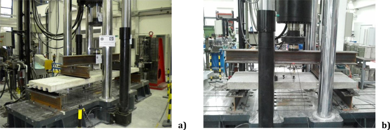
All the experimental tests have been developed at the STRENGTH laboratory (STRuctural ENGineering Test Hall) of the University of Salerno through the test setup reported in Fig. (1). In particular, as an example, the positioning of the four transducers on specimens L3200 is reported in Fig.( 2).
Flexural tests have been executed considering the specimens constrained at the ends by means of a roller and a hinge while the two concentred forces have been applied at a distance equal to L/4 from the supports, where L is the clear length of the specimens. The specimens during their instrumentation are shown in Fig. (2).
The load has been applied by a vertical hydraulic actuator (load capacity 3000 kN) divided into two nominally equal actions through a HE200B steel profile.
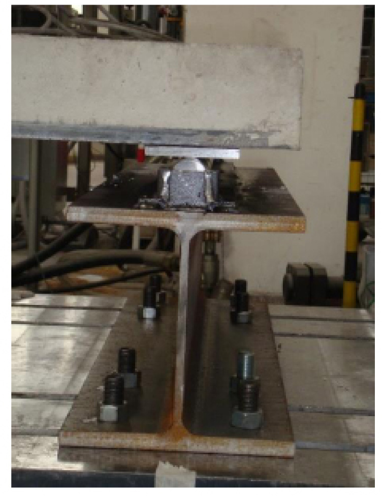
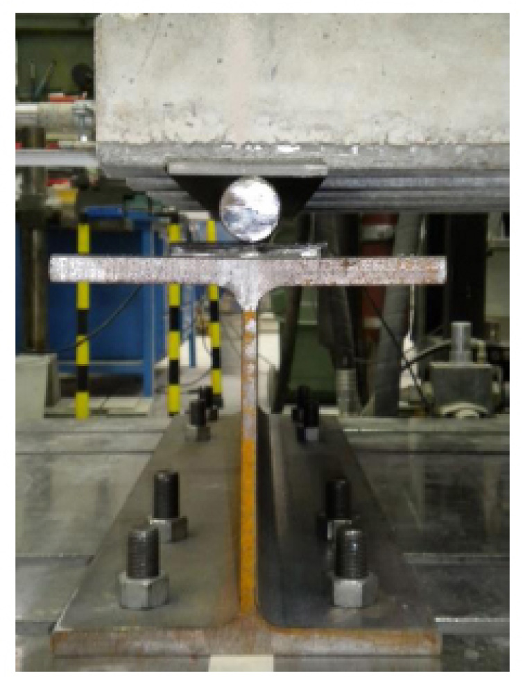
At one end of the slab, the constraint is represented by a hinge made by means of a steel plate (800x100x10mm), resting on a steel roller, which is prevented from sliding horizontally through lateral retainers (Fig. 3). While at the other end of the composite slab, a sliding support has been realized by means of a steel roller with a diameter of 40mm and a length of 800mm (Fig. 4).

During the tests, the load force was monitored by means of load cell “LT Lonos Test” with maximum loading capacity equal to 200 kN in compression, while the displacements were acquired by means of LVDT transducers “Luchsinger LDT 700”. The compression tests on the concrete coupons were carried out simultaneously to the corresponding composite sheets.
The results of the tests on the two series of coupons are summarized in Table 1. In particular, with reference to the concrete coupons, the mean values of the resistance are equal to 28.3 MPa and 28.1 MPa for the coupons of set 1 and set 2, respectively. The results of the tensile tests on the sheet are shown in Table 2. The mean value of the yield resistance is greater than the nominal one and, in particular, is equal to 290.3 MPa.
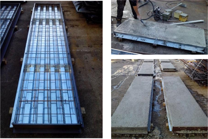
The cross-section of the tested elements is represented in Fig. (5), while in Fig. (6), the realization phases of the specimens are illustrated.
| - | Coupon |
Weight [kg] |
Dimensions [cm] |
Resistance [MPa] |
||
|---|---|---|---|---|---|---|
| Set 1 | 1 | 8.09 | 15.3 | 15.5 | 15.2 | 31.5 |
| 2 | 8.04 | 15.2 | 15.4 | 15.3 | 34.0 | |
| 3 | 7.90 | 14.9 | 15.4 | 15.1 | 26.0 | |
| 4 | 7.90 | 15.4 | 15.2 | 15.3 | 21.5 | |
| - | - | - | - | - | - | |
| - | - | - | Mean Value | 28.3 | ||
| Set 2 | 1 | 8.09 | 15.0 | 15.6 | 15.0 | 31.0 |
| 2 | 8.14 | 15.8 | 15.3 | 15.2 | 34.5 | |
| 3 | 7.90 | 15.1 | 14.9 | 15.2 | 24.5 | |
| 4 | 7.91 | 15.0 | 15.0 | 15.0 | 22.2 | |
| - | - | - | = | - | - | |
| - | - | - | Mean Value | 28.1 | ||
| Coupon |
Thickness [cm] |
Width [cm] |
Yield Resistance [MPa] |
|---|---|---|---|
| 1 | 0.81 | 48.0 | 289.5 |
| 2 | 0.79 | 52.0 | 290.3 |
| 3 | 0.80 | 49.0 | 291.0 |
| - | - | Mean Value | 290.3 |
From Fig. (6), it could be possible to observe the presence of a welded mesh ϕ6/15x15 and the crack inducers.
The specimens are subjected to the concentrated force and, simultaneously, to the distributed load corresponding to the weight of the profiles used for the load application (IPE200-HE200B-cylinderD40=218.45kg) and to the dead weight (Set 1=366.20kg; Set 2=219.72kg)).
Therefore, in order to take into account the increase in the value of the applied force measured by means of the load cell, due to the additional loads, the maximum force F and the maximum bending moment M corresponding to the real load distribution have been summarized in Table 3.
| - | specimen | Maximum load F [kN] | Maximum Moment M [kNm] |
|---|---|---|---|
| Set 1 | H55 - L3200 - MON | 42.10 | 15.79 |
| H55 - L3200 - CYC+MON 1 | 43.85 | 16.44 | |
| H55 - L3200 - CYC+MON 2 | 44.08 | 16.53 | |
| Set 2 | H55 - L1920 - MON | 53.44 | 11.49 |
| H55 - L1920 - CYC+MON 1 | 56.72 | 12.19 |
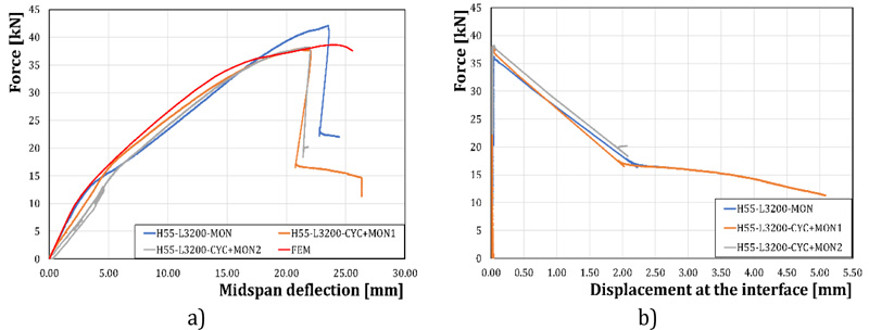
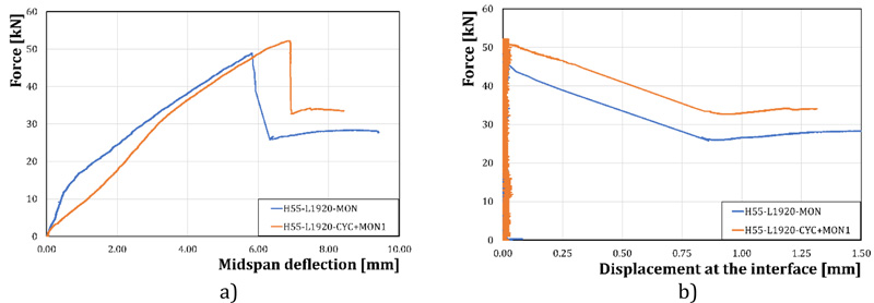
With reference to the tests of the Set 1 specimens, the results have been reported in Fig. ( 7 ) . In detail, the maximum force F versus the midspan deflection - measured by means of the LVDT transducers n.2 and n.4 - (Fig. 7a ) and the maximum force F versus the displacement at the steel-concrete interface - acquired by means of the LVDT transducers n.1 and n.3 - (Fig. 7b ) have been reported in the graphs. Similarly, In Fig (8 ), the results of the set 2 experimental tests have been reported.
3. RESULTS
3.1. Determination of the Composite Floor Resistance
On the basis of the experimental results, the slip resistance at the steel-concrete interface has been evaluated, applying the partial interaction method codified by UNI EN 1994-1-1 [20] and herein introduced. The application of this method needs the evaluation of the resistance domain of the specimens in order to evaluate the interaction factor
3.1.1. Determination of the Bending Resistance Domain
The check-in bending of a composite floor may be based on elastic-plastic or plastic material modeling. Clearly, for hand calculations, the fully plastic approach is simpler to apply and fully in agreement with EC4 provisions. The fully plastic approximation is unconservative because part of the steel of the metal decking may not be yielded at the achievement of the ultimate deformation of the concrete slab. Similarly, concrete may not be fully yielded at failure. Nevertheless, comparisons with experimental results have shown that these simplified assumptions can still provide acceptable results for practical applications. In the check methodology that is currently considered well-established for the usual design practice, the following assumptions are made: i) concrete in tension is not contributing to the overall resistance;ii) plane sections remain plane after the deformation and no uplift of the concrete slab occurs;iii) for simplicity, concrete web contribution is neglected when considering sagging bending moments:iv) no slip occurs at the concrete-steel interface;v) the longitudinal reinforcement for a negative bending moment is limited so that, normally, the neutral axis is within the sheeting. Hypothesis iv) may be removed, as explained later, when describing the partial interaction methodology suggested by Eurocode 4 [20]. Based on these assumptions, the following equations will be derived only for sagging bending moments since, in all the examined cases, the specimens are always subjected to this stress.

For the determination of the domain, the tensile resistance of the sheet and the compressive resistance of the concrete are to be determined in order to identify the position of the neutral axis. In particular, the tensile resistance of the sheet is equal to:
 |
(1) |
Where, As is the sheet area, ƒys is the yielding resistance of the steel and Ys is the partial safety factor for steel [44] fixed equal to 1 because coupon tests have been performed.
The compressive resistance of the concrete is equal to:
 |
(2) |
Where, ƒc is the effective compressive resistance of the concrete, b and hc define the slab geometry, αc is the coefficient taking account of long term effects on the compressive strength and of unfavorable effects resulting from the way the load is applied equally to 0.85 [45] and Yc is the partial safety factor for concrete fixed equal to 1 because coupon tests have been performed.
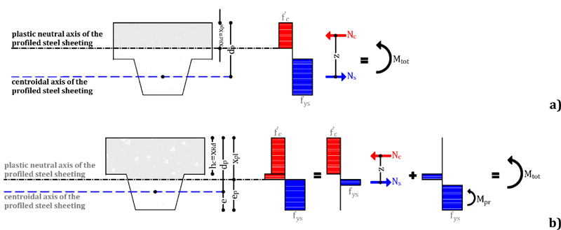
Depending on the position of the neutral axis (Fig. 9), different design equations can be written.
When the neutral axis is in the concrete flange (above the sheeting), its position is evaluated as (Fig.9a):
 |
(3) |
As a consequence, the force transmitted by the steel sheeting is given by:
 |
(4) |
and the lever arm z is evaluated as:
 |
(5) |
Differently, when the neutral axis is in the concrete web (within the sheeting), its position is evaluated as (Fig.9b):
 |
(6) |
Because of the aforesaid assumptions considered in the common practice,
the force transmitted by the steel sheeting is given by:
 |
(7) |
In this case, the lever arm is evaluated as:
 |
(8) |
Where, e* represents the conventional position of the tensile force acting in the metal decking, which is defined according to EC4 methodology as:
 |
(9) |
In this equation, e represents the position of the centroidal axis of the metal decking (it can be calculated by simply equating to zero the first moment of area). Conversely, ep is called plastic barycentre of the metal decking and corresponds to the position of the neutral axis when the sheeting is subjected to pure bending. Considering a rigid-plastic approach, it can be calculated by simply equating the areas above and under the neutral axis. From the practical point of view, the previous equation linearly interpolates the position of the tensile force acting in the decking, considering the two extreme situations which can arise in practical applications. The first is when the steel sheeting is under pure tension: in this situation, the neutral axis is located at the upper edge of the metal decking xpl = hc and, therefore, the sheeting is in pure tension. In this case, the axial force is applied in the geometrical barycentre of the steel decking (e). Subsequently, it is possible to define the resistance domain of the composite slab fixing the positions of the neutral axis x starting from its maximum value XRd defined in the case of η = 1 to a minimum value equal to 0. For each value of the position the neutral axis is possible to define the force transmitted by the sheet Nc by means of Eq. (4) and the interaction factor η as:
 |
(10) |
The plastic moment of the sheet in case of partial interaction Mpr, according to Eurocode 4 [20], is given by:
 |
(11) |
Where, Mpl.Rd is the plastic moment of the sheet. The flexural resistance of the composite decking is given by the sum of the contribution of sheeting and slab:
 |
(12) |
Therefore, considering the experimental values of the materials resistances, the parameters of the resistance domain has been evaluated and reported in Table 4 with reference to the specimens of set 1 and set 2.
3.1.2. Determination of the Longitudinal Shear Strength
The evaluation of the longitudinal shear strength is made by means of the partial interaction method that is based on a more accurate physical interpretation of the interaction mechanism arising between the concrete slab and metal decking. With the partial interaction method, the hypothesis of full connection is removed, while concrete and steel are assumed to be only partially connected. In this case, shear-bond tests data are used to define the ultimate resistance for longitudinal shear, expressed usually in terms of stress τu. Such stress represents the value at which a relative longitudinal slip between the concrete slab and metal decking occurs due to the overcoming of the bond resistance. It is worth observing that, in this model, even though the longitudinal stresses arising between concrete and steel decking are distributed along the lateral surfaces of the sheeting, the longitudinal shear resistance is conventionally calculated dividing the experimental value of the longitudinal shear force by the composite floor width b ( Table 5). The behavior of the interface, within this modeling approach, is assumed to obey a Mohr-Coulomb law, in which the stress normal to the sliding surface is assumed to be equal to the reaction at the support Vt. Nevertheless, in most of the practical cases, the effect of the transversal stress is neglected, and the longitudinal resistance is computed, referring only to the cohesive contribution (adhesion or bonding). The mechanical modeling in the partial interaction method is based on the assessment of the plastic resistance of the composite cross-section accounting for the effect of the partial shear connection.
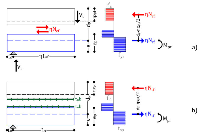
Making reference to the case of a sagging bending moment, from Fig. (10a), it can be easily recognized that owing to equilibrium conditions, the shear force in the connection Vt is equal to the compression force acting in the concrete flange. The compressive force in the slab calculated under the assumption of full interaction Ncf, in general, depending on the distance of the considered section from the point of zero moments, may be higher or lower than the resistance of the shear connection. In fact, considering simple equilibrium conditions, the longitudinal shear connection resistance in the hypothesis of rigid-plastic behaviour at the generic abscissa (Fig. 10b), is equal to τub(L0 + Ls), where (L0 + Ls) is the distance of the cross-section being considered from the point of zero bending moment (Fig. 1). The partial interaction factor η = τub(L0 + Ls),/Ncf assume values lower than 1 and must be higher than zero.
Specifically, considering that at the point of zero bending moment, (L0 + Ls) is equal to zero, in the same section η is zero. Conversely, moving far from the point of zero moment, the resistance of the shear connection increases and so does the partial interaction factor. A unitary value of τu is achieved when the distance of the considered section from the point of zero bending moment becomes at least equal to LsƒNcf/τub.
In the examined cases, the ultimate resistance for longitudinal shear can be determined as:
 |
(13) |
Where, η is the partial interaction factor corresponding to the maximum bending moment reached during the tests and reported in Table. 3, and Ncf, b and (Ls + L0) are the parameters previously described.
Finally, according to EC4 [20], starting from the experimental of longitudinal shear strength of a composite slab, its characteristic value can be obtained by means of the following equation:
 |
(14) |
Where, ηk is the interaction factor determined by means the resistance domain of the specimen using the maximum moment reached during the test, mτuu is the mean value of the obtained experimental results (in terms of τu) and Vτu is the coefficient of variation evaluated as follows:
 |
(15) |
Where, η is the number of the executed tests. The value of the coefficient kη is reported in Tab D1 of EN1990 - annex D [46] as a function of the number of experimental tests. In the analysed case,
 |
Therefore, the characteristic value of longitudinal shear strength of the composite slab determined by means of Eq. (14) is equal to 0.225 N / mm2 being the Sτu = 0.036 and Vτu = 0.10.
4. DISCUSSION
4.1. Finite Element Modeling
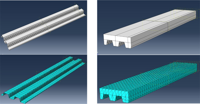
In order to evaluate the influence of the geometrical and mechanical parameters on the longitudinal shear strength at concrete-steel sheeting interface, numerical simulations by means of advanced finite element model have been performed using ABAQUS 6.14 software [27]. The finite element 3D-model has been developed according to the following steps: geometrical characterization of the components, definition of material properties, definition of the interactions between the elements, definition of the boundary conditions and choice of the elements and definition of the size of the mesh (Fig. 11).
| Set 1 | xRd | Nc | ηk | Mpr | z | Mtot | Set 2 | xRd | Nc | ηk | Mpr | z | Mtot |
|---|---|---|---|---|---|---|---|---|---|---|---|---|---|
| [mm] | [kN] | [kNm] | [mm] | [kNm] | [mm] | [kN] | [kNm] | [mm] | [kNm] | ||||
| 0.00 | 0.00 | 0.00 | 5.04 | 82.50 | 5.04 | 0.00 | 0.00 | 0.00 | 5.04 | 82.00 | 5.04 | ||
| 0.77 | 11.90 | 0.05 | 5.04 | 82.12 | 6.02 | 0.77 | 11.90 | 0.05 | 5.04 | 81.62 | 6.02 | ||
| 1.53 | 23.80 | 0.10 | 5.04 | 81.73 | 6.99 | 1.53 | 23.80 | 0.10 | 5.04 | 81.23 | 6.98 | ||
| 2.30 | 35.71 | 0.15 | 5.04 | 81.35 | 7.95 | 2.30 | 35.71 | 0.15 | 5.04 | 80.85 | 7.93 | ||
| 3.07 | 47.61 | 0.20 | 5.04 | 80.97 | 8.90 | 3.07 | 47.61 | 0.20 | 5.04 | 80.47 | 8.87 | ||
| 3.83 | 59.51 | 0.25 | 4.73 | 80.58 | 9.52 | 3.84 | 59.51 | 0.25 | 4.73 | 80.08 | 9.49 | ||
| 4.60 | 71.41 | 0.30 | 4.41 | 80.20 | 10.14 | 4.60 | 71.41 | 0.30 | 4.41 | 79.70 | 10.11 | ||
| 5.37 | 83.32 | 0.35 | 4.10 | 79.82 | 10.75 | 5.37 | 83.32 | 0.35 | 4.10 | 79.32 | 10.71 | ||
| 6.13 | 95.22 | 0.40 | 3.78 | 79.43 | 11.35 | 6.14 | 95.22 | 0.40 | 3.78 | 78.93 | 11.30 | ||
| 6.90 | 107.12 | 0.45 | 3.47 | 79.05 | 11.94 | 6.90 | 107.12 | 0.45 | 3.47 | 78.55 | 11.88 | ||
| 7.67 | 119.02 | 0.50 | 3.15 | 78.67 | 12.52 | 7.67 | 119.02 | 0.50 | 3.15 | 78.16 | 12.46 | ||
| 8.43 | 130.93 | 0.55 | 2.84 | 78.28 | 13.09 | 8.44 | 130.93 | 0.55 | 2.84 | 77.78 | 13.02 | ||
| 9.20 | 142.83 | 0.60 | 2.52 | 77.90 | 13.65 | 9.21 | 142.83 | 0.60 | 2.52 | 77.40 | 13.58 | ||
| 9.97 | 154.73 | 0.65 | 2.21 | 77.52 | 14.20 | 9.97 | 154.73 | 0.65 | 2.21 | 77.01 | 14.12 | ||
| 10.73 | 166.63 | 0.70 | 1.89 | 77.13 | 14.74 | 10.74 | 166.63 | 0.70 | 1.89 | 76.63 | 14.66 | ||
| 11.50 | 178.53 | 0.75 | 1.58 | 76.75 | 15.28 | 11.51 | 178.53 | 0.75 | 1.58 | 76.25 | 15.19 | ||
| 12.27 | 190.44 | 0.80 | 1.26 | 76.37 | 15.80 | 12.27 | 190.44 | 0.80 | 1.26 | 75.86 | 15.71 | ||
| 13.03 | 202.34 | 0.85 | 0.95 | 75.98 | 16.32 | 13.04 | 202.34 | 0.85 | 0.95 | 75.48 | 16.22 | ||
| 13.80 | 214.24 | 0.90 | 0.63 | 75.60 | 16.83 | 13.81 | 214.24 | 0.90 | 0.63 | 75.10 | 16.72 | ||
| 14.57 | 226.14 | 0.95 | 0.32 | 75.22 | 17.33 | 14.58 | 226.14 | 0.95 | 0.32 | 74.71 | 17.21 | ||
| 15.33 | 238.05 | 1.00 | 0.00 | 74.83 | 17.81 | 15.34 | 238.05 | 1.00 | 0.00 | 74.33 | 17.69 |
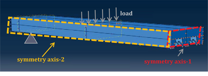
The model is essentially constituted by two elements: the concrete slab and the steel sheeting. For the sake of simplicity, the steel mesh embedded in the concrete slab in this analysis was neglected. In the modeling, the two symmetry axes were considered reducing the number of modelled elements. For the discretization of both the sheet and the slab, finite elements suitable for dividing surfaces characterized by geometric irregularities have been used. In particular, the sheet was modelled using S3 triangular shell elements while the slab was discretized with C3D10 solid tetrahedral elements. The mesh size was established by carrying out preliminary analyses that assured the stability of the results and an acceptable relationship between computational time and accuracy of the results. In particular, both steel sheet and concrete slab were discretized using the same mesh size, with a maximum size of 40 mm of the side of the finite element and a deviation factor of 0.1 of the curved surfaces.
The materials were defined taking into account the non-linear behaviour of both concrete and steel. The mechanical behaviour of concrete was described using the “Concrete Damaged Plasticity” (CDP) model. This formulation allows the modeling of concrete and, in general, fragile materials. The CDP model uses the concept of damaged isotropic elasticity in combination with isotropic plasticity in both tensile and compression sides in order to represent the inelastic behaviour of concrete. CDP is able to take into account the confinement effect of concrete and assumes that the two main collapse mechanisms are tensile cracking and compression crushing. The identification of the parameters of the CDP model for concrete, in general, can be carried out starting from compression and uniaxial tension experimental tests, from the knowledge of the collapse curve in case of biaxial stress and from triaxial tests at different confinement stresses. In the examined cases, only the ultimate values of the compression tests on cubic specimens are available, therefore, it was necessary to refer to mathematical models and to literature values. In particular, the uniaxial behaviour of concrete was described in accordance with the Saenz constitutive low [47] (Fig. 12a), while the tensile behaviour was defined as linearly degrading by specifying in the software the amount of the fracture energy (Fig. 12b). The plastic parameters assumed are the typical ones recommended by the ABAQUS manual and in particular: dilatancy angle equal to 40°, eccentricity of the potential flow equal to 0.1, ratio between biaxial compression resistance on uniaxial equal to 1.16 and viscosity parameter equal to 0.0001.
The constitutive low of the corrugated sheet was defined starting from the experimental tests on the material which, for the analysed steel (S280D), showed an elastic-perfectly plastic behaviour without significant strain hardening. Therefore, steel was defined using an elastic-plastic isotropic low with yield stress defined in accordance with the tests on materials previously reported.
The definition of the interaction between the sheet and the concrete is fundamental for the prediction of the elastic and plastic behaviour of the composite floor. In this work, the interaction has been defined both in the normal and tangential directions by inserting a cohesive link between the interface of the elements. The introduction of the cohesive link establishes a kinematic relationship between the nodes of the two surfaces, necessary to model the friction and the adhesion of the sheet-concrete, as well as the phenomena of detachment and loss of adhesion in the normal direction of the surface. The assumed cohesive interaction is characterized by an elastic initial branch with complete loss of adherence when the maximum tangential tension is achieved. Stiffness and strength of the cohesive constitutive low have been determined according to the mathematical model proposed by Verderame et al. [48, 49] based on experimental pull-out tests on smooth bars. For the modeling, a shell-to-solid interaction formulation was adopted as provided by ABAQUS. In the shell-to-solid of Abaqus, constraints are assembled coupling both the displacements and rotations of each shell node to the average displacement and rotation of the solid surface in the vicinity of the shell node.
The boundary conditions were defined in order to fix the symmetry conditions on the slab and sheet edges which, as mentioned before, was modelled with reference to a quarter of a specimen. Therefore, the longitudinal displacements of the nodes, at symmetry axis-1, were constrained, while at symmetry axis-2, the transverse displacements was fixed. The slab was constrained at the support by suppressing the vertical displacements. In addition, as in the experimental test, a roller with vertical axis was introduced. The external action was applied in displacements control in the section corresponding to the experimental loading point, imposing a lowering of 40 mm (Fig. 13).
4.1.1. Validation of the FE Model and Parametric Analysis
The FE simulation of the behavior of the specimen of Set1, subjected to flexural tests, have been performed. The comparison between the analytical and experimental results shows an adequate prevision in terms of stiffness, resistance, and ductility supply (Fig.14a). In particular, the ultimate resistance obtained in the FEM analysis is similar to the experimental one demonstrating the possibility of predicting the ultimate sliding force by means of an accurate finite element simulation of the steel-concrete interaction mechanisms. In fact, the ratio between the ultimate resistance and the average value of the experimental resistance is equal to 0.974.
Starting from the obtained results, a preliminary parametric analysis has been carried out evaluating the influence of the thickness of the sheet on the ultimate resistance of the composite floor and, therefore, on the longitudinal shear resistance defined in EC4. The results of the FEM analysis performed considering an increasing thickness of 10/10 and 12/10 mm with the same shape and depth of the tested sheet is reported in Fig. (14b). It can be noted that as the thickness increases, stiffness and strength gradually increase, while a decrease in ductility is observed.


The application of the partial interaction method proposed by EC4 allows to evaluate the influence of the sheet thickness on the conventional value of the longitudinal shear strength (Table.6). In Table 6, starting from the FE results, through the procedure suggested by EC4, based on the partial interaction method, the longitudinal shear resistance has been calculated for three different configurations. The procedure applied is that described in section 3, based on the assessment of the failure load and partial interaction domain. The results show the influence that the sheeting thickness has on the conventional value of the longitudinal shear resistance. In addition, the comparisons show that the prediction for the 8/10 mm matches rather well than the experimental response providing only a slight approximation (ration between experimental/ FEM=0.346/0.352=0.985). This work represents only a first step and, up to now, only few comparisons have been made, while in subsequent steps of the same work, the authors intend to extend the number of cases investigated so as to perform a parametric validation of the partial interaction method suggested by EC4.
|
Average Experimental Value [MPa] |
FEM Value 8/10mm [MPa] |
FEM Value 10/10mm [MPa] |
FEM Value 12/10mm [MPa] |
|---|---|---|---|
| 0.346 | 0.352 | 0.312 | 0.284 |
In particular, it is possible to note that the resistance decreases with increasing thickness, varying from 0.35 MPa to 0.28 MPa, considering a sheet from 8/10 to 12/10 mm. This underlines that the value of the longitudinal stress estimated by EC4 for a certain thickness cannot be straightforwardly extended to other thicknesses. Nevertheless, since the longitudinal stress decreases with the increase of the thickness, it can be concluded that the experimental estimate obtained with certain thickness can be adopted as a conservative estimate for design purposes only for thinner sheeting.
CONCLUSION
In this work, the behavior of a composite floor composed of corrugated steel sheet and concrete slab has been examined, evaluating the capability to transfer stress at the concrete-steel interface by means of experimental and numerical analysis. In particular, five experimental tests on the composite floor have been carried out and the characteristic longitudinal shear resistance has been assessed applying the method of partial interaction provided by EC4. Subsequently, starting from the experimental results, a finite element model was developed in ABAQUS software in order to simulate the behavior of the composite floor both in terms of applied force versus midspan deflection and in terms of applied force versus displacement at the steel-concrete interface. The FEM modeling allows the investigation of the role of geometric and mechanical parameters on the sliding resistance at sheet and concrete interface. To this scope, a first parametric analysis has been developed investigating the influence of the thickness of the sheet. On the base of the preliminary results obtained, the main conclusions are:
• The finite element analyses allow to demonstrate that as the thickness increases, stiffness and strength gradually increase while ductility decreases;
• The longitudinal shear resistance decreases with the increase of the thickness of the sheet.
• Future analyses will be devoted to the evaluation of the role of mechanical properties ofmaterials and on shape and geometrical properties of the sheet.
CONSENT FOR PUBLICATION
Not applicable.
AVAILABILITY OF DATA AND MATERIALS
Not applicable.
FUNDING
None.
CONFLICT OF INTEREST
The authors declare no conflict of interest, financial or otherwise.
ACKNOWLEDGEMENTS
Declared none.


