All published articles of this journal are available on ScienceDirect.

Seismic Vulnerability Assessment of Existing Italian Hospitals: The Case Study of the National Cancer Institute “G. Pascale Foundation” of Naples
Authors Info & Affiliations
Abstract
Introduction:
A large portion of the Italian built heritage is characterized by a significant seismic vulnerability since many structures were designed with outdated criteria, i.e., without accounting for seismic actions. This aspect is particularly relevant for strategic structures and infrastructures, whose functionalities are crucial in case of seismic events.
Objective:
The main aim of the present paper is to share the key findings related to the seismic vulnerability assessment of the National Institute for the Study and Treatment of Cancer (IRCCS) “Giovanni Pascale Foundation” in Naples. In particular, the main evidences could be easily extended to existing hospitals realized in the last century, with the main reference to: construction techniques, quality of constructional material, overt and convert seismic vulnerabilities and possible intervention strategies for risk mitigation.
Methods:
In the present paper, the assessment methodologies adopted for such a strategic hospital complex are provided, focusing in particular on: i. preliminary research of original design documents and on-site investigation for determining constructional details; ii. material tests on structural elements; iii. vulnerability seismic assessment by means of non-linear FE analyses (push-over and capacity spectrum method); iv. recommendations on retrofitting measures and cost estimations.
Results:
The conducted study puts into clear evidence the inadequacy of the investigated buildings to face the design seismic actions provided by the current Italian code and thus showed the significant seismic vulnerabilities affecting the Institute “G. Pascale Foundation” of Naples. Among these, particular attention has also been focused on the so-called intrinsic vulnerabilities, namely the ones not measurable explicitly and interesting non-structural elements (e.g., connection of shelves, stained glass windows, facilities, etc.).
Conclusion:
The presented case study highlights the strong seismic vulnerability affecting structures realized in the past century, despite their strategic functions. On the whole, the examined structures can be considered as representative of this building typology, and the adopted calculation criteria, as well as the assumptions of the assessment process, could be easily extended to similar case studies.
1. INTRODUCTION
The seismic vulnerability of existing buildings is an issue of primary importance, which also interests strategic structures. This is particularly relevant in seismic-prone areas, especially where the building stock is affected by a significant ancientness, such as in Italy [1, 2]. Indeed, according to a qualitative estimation provided by the National Department of Civil Protection (DPC), in Italy, there are about 75000 public buildings realized without accounting for seismic criteria, and at least half of them are placed in areas affected by a significant seismic hazard [3].
Given the large scale of the problem in this zone, following the collapses of many strategic buildings due to the seismic event that occurred in Molise (October-November 2002), in 2003 an Ordinance of the President of the Ministers’ Council [4] has set the tone for solving such a situation. In particular, it gave a mandatory temporal limit of five years to assess the seismic vulnerability of strategic structures and infrastructures (e.g., hospitals, headquarters of the Department of Civil Protection, bridges, etc.), whose functionalities are crucial in case of seismic emergency. Such a limit was subsequently postponed several times; nevertheless, nowadays, there are many strategic structures for which a seismic vulnerability assessment is still missing.
Among all typologies of strategic buildings, particular attention should be focused on medical facilities. Indeed, it can be qualitatively stated that about a quarter of the Italian hospitals are placed in historical buildings, namely realized before 1900, while another large portion was erected after the post-World War II. These data highlight the potential seismic vulnerability affecting this type of structures, as well as the need to adopt far-sighted policies aimed at guaranteeing their functionality in case of seismic emergency. In this context, many studies have been carried out by several authors concerning both Italian and world-spread medical facilities by means of different approaches: from the most general ones (i.e., at a large-scale) [5-11] to the most specific ones (i.e., at a single-scale level) [12-15]. These studies clearly highlighted the unacceptable seismic vulnerabilities affecting such strategic structures, whose function is crucial in case of seismic events.
The present study deals with the seismic vulnerability assessment procedure that has recently interested one of the most important hospitals of southern Italy, namely the cancer institute “G. Pascale Foundation” of Naples. For the development of the structural assessment of such a building, the professional service has been carried out by the AIRES Engineering of Caserta, while the activity has been validated by the supervision of the Department of Architecture and Industrial Design of the University of Campania Luigi Vanvitelli.
The whole activity has been phased in four different steps, as follows:
● Phase 1: acquisition of historical information and geometrical survey, which are essential for reaching a good level of knowledge of the investigated structures;
● Phase 2: destructive and non-destructive on-site tests aimed at mechanically characterizing the existing materials;
● Phase 3: implementation of Finite Element Models (FE Model) for running non-linear analyses aimed at evaluating the safety level of each building constituting the investigated hospital facility;
● Phase 4: recommendation of retrofitting provisions to guarantee the functionality of the structures in case of seismic events.
The main aim of presenting this case study is to share the complex procedure behind the seismic safety assessment of an articulated medical facility, such as the one under investigation. In addition, a critical approach is proposed for defining the investigation campaign and the mechanical characteristic of the existing materials. Given the typical structural features of the period, as well as the fragility factors returned by the assessment process, the investigated buildings could be considered very representative of this typology of structures mainly realized more than fifty years ago. Hence, the Authors have found it interesting to share the key findings obtained during the activities, providing in detail the entire assessment process. Finally, a section of the manuscript is also devoted to the possible structural interventions to be applied in order to ensure a sufficient seismic capacity of the structures.
2. MATERIALS AND METHODS
2.1. The Investigated Buildings
2.1.1. General
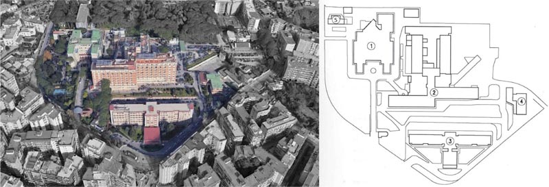
The National Institute for the Study and Treatment of Cancer (IRCCS) “Giovanni Pascale Foundation” in Naples is composed of five independent buildings whose total plan extension, also comprising the access zones and car parks, amounts to about 60000 m2. A satellite view of the entire complex and a general plan with the position of the different buildings are provided in Fig. (1), where:
- Edifice 1 is the “Scientific Building” (hereinafter stated as [SB]);
- Edifice 2 is the “Hospitalization Building” (hereinafter stated as [HB]);
- Edifice 3 is the “Day-Hospital Building” (hereinafter stated as [DH]);
- Edifice 4 is the “Administrative Building” (hereinafter stated as [AB]);
- Edifice 5 is the “Nun Building” (hereinafter stated as [NB]).
It is worth mentioning that Edifice 1 [SB] has not been involved in the assessment process, and Edifice 2 [HB] consists of several structural units, as better shown in the following section.
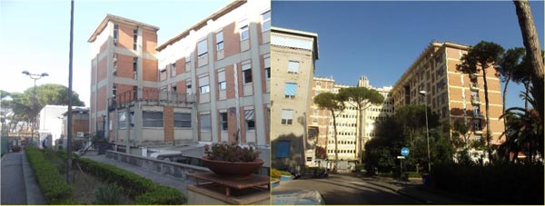
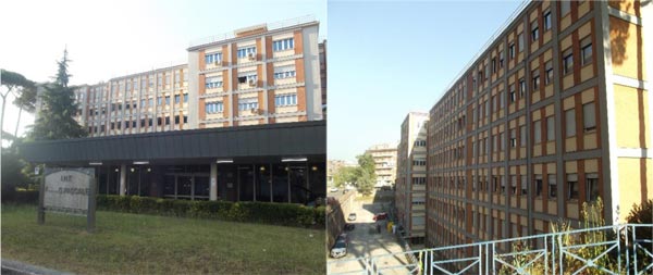
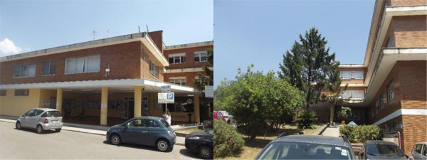
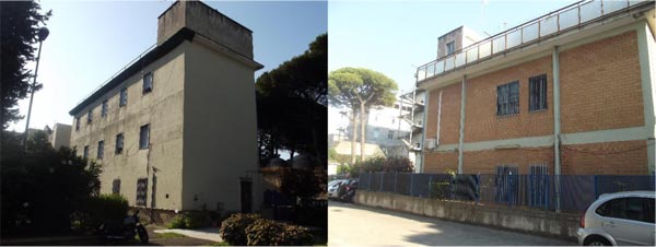
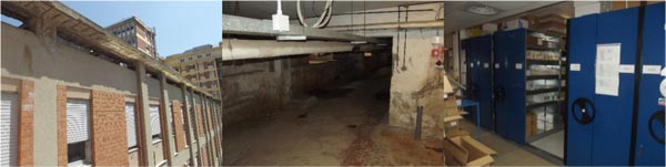
The predominant construction materials of the structures of the “G. Pascale” Institute are reinforced concrete and steel. In particular, [HB] and [AB] buildings were entirely realized in reinforced concrete, while [DH] presents beams and columns in structural steel with r.c. cores and [NB] consists of two different portions made of masonry and r.c. Some photos of the investigated buildings are shown in Figs. (2-5).
2.1.2. Available Information
The activities started with a wide research aimed at finding all the historical information necessary to achieve a deep knowledge of the investigated structures. The history of the hospital complex has been reconstructed in detail. In particular, the realization of the first building, i.e., [SB], began in March 1934. Probably, it is hypothesized that in the same period, the masonry portion of the [NB] was erected, too. Between 1960 and 1985, several enlarging projects of the hospital were drawn up, which have deep transformed its organization and have led to the complex architectural and structural system that nowadays distinguishes the entire hospital plexus.
As far as the construction time of each building is concerned, by means of the obtained documents and some oral information, it has been possible to determine the historical evolution of the “G. Pascale Foundation” as follows:
- The first enlargement of the original hospital (intended as the “Scientific Building”) dates back to February-August 1961 and consisted of realizing a small portion of the unit A of the [HB] building (the first two stories);
- Between June and November in 1968, the [HB] building was significantly expanded by adding two additional stories and a staircase attached to unit A and by erecting the units B, C and D;
- The following year, between February and June, a portion of the units F and G of the [HB] building were built;
- In the period between November 1975 and December 1980, all the units of the [HB] building were completed;
- The realization of the [AB] and [DH] dates back to the period between June 1977 and August 1982.
As far as the [NB] is concerned, it can be assumed that the erection of the masonry portion was completed in the same period of the [SB], while the r.c. structure dates back after 1980, despite precise information have not been found.
2.1.3. Description of the Buildings
2.1.3.1. The Hospitalization Building [HB]
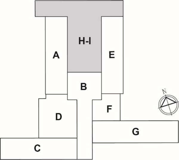
The Hospitalization Building is characterized by a very articulated plan shape: from a central volume (unit B) having a “T” shape and with a North-South orientation, the various units detach, as shown in Fig. (6). It is worth noticing that the portion “H-I” has not been the object of investigation since a seismic retrofitting intervention was already designed when the activities started.
All the investigated structural units of [HB] present an underground floor, while a very heterogeneous in-elevation development characterizes them. In particular, the highest units, i.e., B, C and G, consist of additional ten aboveground floors, while the shortest ones, i.e., F and H-I, are two-story buildings. Moreover, units E and A present five and four aboveground stories, respectively, while D has two intermediate-level floors in addition to the underground one. Then, two vehicular ramps are present, which permit the connection between the ground floor of C and F units to the external ground level. From a structural point of view, all the units are independent between themselves since they are separated by means of technical joints (i.e., Gerber supports).
Unit A, which is the most complex one, can be in turn considered composed of three independent structural sub-units: A1, A2 and A3. The sub-unit A1 is affected by a strong historical stratification since many interventions aimed at improving existing structures due to change of use or enlargement have been made. From a structural point of view, it consists of mono-directional r.c. frames with transversal beams placed both along the perimeter (having infill-bearing scopes) and in intermediate positions, which support limited inverted-oriented portions of the slab. As far as the horizontal structures are concerned, they are mainly West-East oriented and consist of different typologies in the function of their destination of use. In particular, r.c. with hollow blocks slabs, solid r.c. slabs and concrete slabs with embedded steel beams are present in this sub-unit. On the other hand, the sub-unit A2, which represents the staircase of the sub-unit A1, consists of a r.c. structure with beams and cantilever steps, while the A3 one is a two-story r.c. structure with hollow blocks slabs. The foundation system of all sub-units is of the superficial type.
Unit B is characterized by r.c. frames, which are oriented in both directions and four r.c. cores. It presents eleven stories, and the horizontal structures are made of r.c. with hollow blocks slabs. The foundations consist of plinths supported by piles.
Unit C also presents eleven stories and consists of eight mono-directional r.c. frames (oriented in the North-South direction) and infill-bearing perimeter beams. Moreover, in the basement, some r.c. walls are present, which are obtained from the union of the upper-story columns. The horizontal structures consist of r.c. with hollow blocks slabs, while the foundations are of the deep type (i.e., plinths supported by piles). The access to unit C is guaranteed by means of a straight carriageable r.c. ramp having a slope of about 10% and a circular arrival square at the level of the ground floor of the unit. The structure of the ramp is characterized by a r.c. solid slab supported by pillars founding on a superficial system of foundation.
The structure of unit D consists of three-story r.c. frames oriented in the North-South direction with typical r.c. with hollow blocks slabs. Moreover, this unit has been recently subjected to an enlargement intervention, namely a steel structure connected to the r.c. beams have been realized. Also in this case, the foundations consist of plinths on piles.
The next investigated unit of the [HB] is the E one, which is a six-story building with frames oriented in the sole North-South direction. The first two levels present r.c. solid slabs, while the remaining horizontal structures are made of r.c. with hollow blocks; superficial foundations support the entire building.
As far as the unit F is concerned, it can be considered composed by two separated sub-units, i.e. F1 and F2. Despite their independency guaranteed by means of a technical joint, the sub-units present similar structural characteristics: They both consist in three-story r.c. frames supported by deep foundation systems. On the contrary, with reference to horizontal structures, different slab types are present: r.c. with hollow blocks and solid r.c. ones have been surveyed.
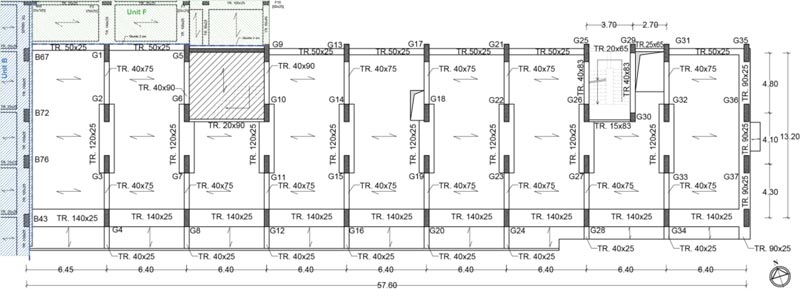
Then, the last unit of the Hospitalization Building is the G one, whose in-height elevation amounts to eleven stories. The structural system consists of nine mono-directional frames (oriented in the North-South direction) and perimeter beams serving as infill bearing. All slabs are of the r.c. with hollow blocks type, with prefab prestressed concrete joists (from first to the fourth story) and cast-in-situ ones (from fifth to the eleventh story). Moreover, an articulated staircase is present, which is prevalently composed of three ramps per story (from second to ninth-story), while it consists of two ramps in the first and tenth stories. Plinths on piles support the unit at issue.
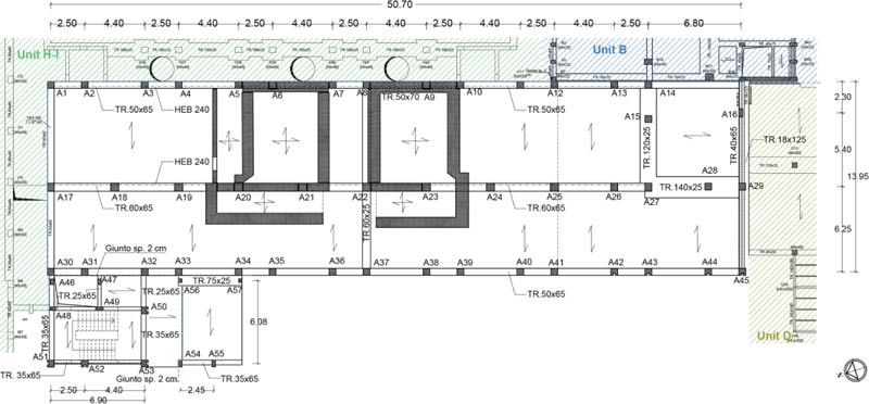
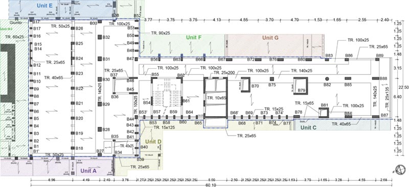
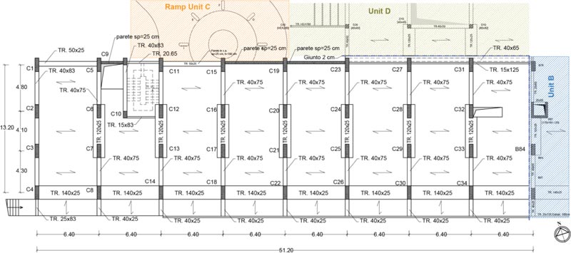
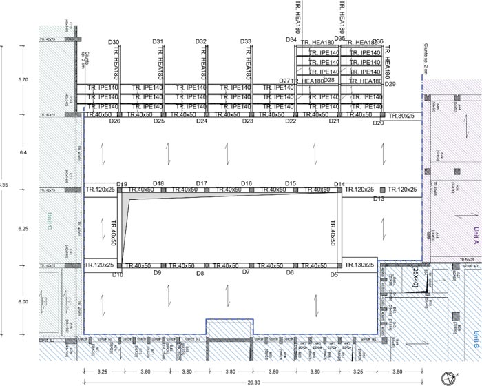
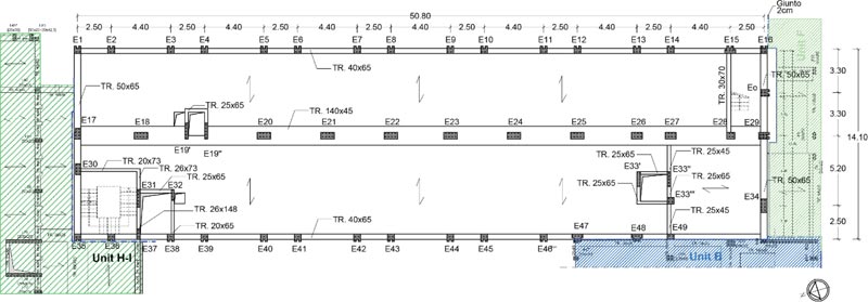
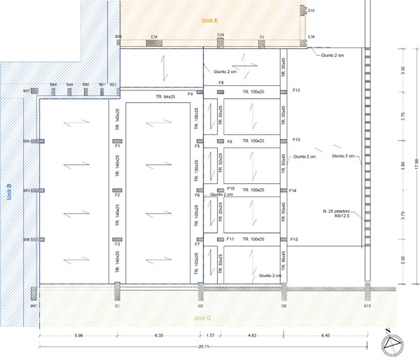
Carpentry plans of the afore-described buildings are provided in Figs. (7-13).
2.1.3.2. The Day-Hospital Building [DH]
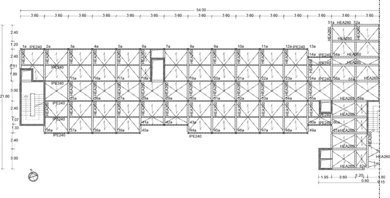
The [DH] building consists of a singular seven-story steel structure integrated with r.c. cores. Moreover, on the ground floor, a single-level artefact, serving as reception, is present, which is independent of the main steel structure. The steel structure consists of steel frames oriented in both direction and with beams connected to full-height columns by means of hinge nodes. Moreover, for each portion of slab, which is composed of a steel trapezoidal sheet and a concrete upper slab and is oriented in the longitudinal direction (West-East), an intermediate steel beam is present, whose aim is to reduce the total span of the slab itself. The seismic-resistant portion of the structure consists of nine r.c. cores (serving as staircases and elevators) disposed of symmetrically with respect to the barycentric vertical axis (North-South direction). On the contrary, the single-level additional portion of this building presents r.c. frames and a curve-shaped wall. The flat roof is a typical r.c. with hollow blocks slab, which distinguishes two portions having different heights. All the foundation systems are deep with pile-cap systems. Some additional information about the structural elements of the [DH] building can be found in Fig. (14), where the sole left half (due to its symmetry) of the carpentry plan is shown.
2.1.3.3. The Administrative Building [AB]
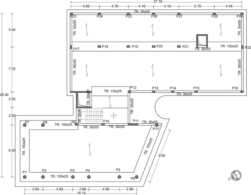
The Administrative building [AB] is an articulated r.c. structure with a similar H-shaped plan. In particular, a central body hosting the staircase and elevator blocks connects the two wings of the building, which have North-South orientation and different dimensions. The West portion of the building presents, on the ground floor, a two-side open space, which serves as an access portico. The whole structure is composed by r.c. frames and walls; the latter work both as structural systems of the two elevator shafts in the central body and as retaining walls in the underground level of the West portion of the building. Horizontal structures prevalently consist of r.c. with hollow blocks slabs with steel trapezoidal sheets, but in the first story of the West portion, the upper slab is in r.c. The superficial foundations consist of inverted T-beams. The [AB] carpentry plan is provided in Fig. (15).
2.1.3.4. The Nun Building [NB]
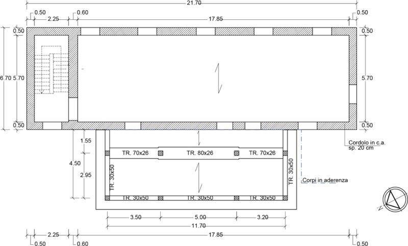
The last building of the medical facility under investigation, i.e. [NB], is composed of two structural units: an original tuff masonry building with an adjacent r.c. concrete portion, which is the result of a subsequent enlargement intervention. With reference to the masonry portion, the plan distribution of the structural elements provides the presence of perimeter walls and of a transversal panel delimiting the staircase placed in the East zone. The thickness of the masonry walls is in the range of 50-60 centimetres and two different types of horizontal structures are present: Hollow block combined with r.c. slab (first and second story) and steel slab (third story). On the other hand, r.c. structure presents frames mainly disposed in the West-East direction with r.c. with hollow blocks slabs, which also present a cantilever portion in the proximity of the connection with the masonry unit. As far as the foundation system of the building under investigation is concerned, it is of the superficial type, with a r.c. curb for both masonry and r.c. portion. In Fig. (16) the carpentry plan of [NB] is shown.
3. RESULTS
3.1. Material Characterization
3.1.1. General
The structural analysis of the existing buildings has been carried out according to the Italian and European technical codes, thus following a “Performance approach” [16-18]. In particular, coefficients to reduce material strengths (namely confidence factors, FC) based on the achieved level of knowledge (KL) have been used. Since a wide preliminary investigation campaign involving both geometries and material tests has been performed, as well as original design documents were prevalently available, the highest level of knowledge (i.e., KL3), to which corresponds a confidence factor FC=1, was adopted for the cases under consideration. In this section, a general description of the destructive and non-destructive tests conducted with the aim to mechanically and geometrically characterize the investigated structural elements, as well as the main outcomes, is provided.
In particular, the wide investigation campaign foresaw: i. compressive tests of cylindrical concrete samples; ii. tensile tests of reinforcement steel bars; iii. tensile tests of steel structural elements; iv. durometer tests of steel structural elements; v. Vickers hardness tests on steel bolts; vi. flat jack tests of masonry elements; vii. pachometer tests or visual inspections on constructional details. A summary of the number of executed tests for each building and story is provided in Tables 1-4.
| - | Compressive Tests on Concrete | Tensile Tests on Steel Bars | Pachometer Tests |
| -2nd floor | 36 | 8 | 44 |
| -1st floor | 25 | 7 | 61 |
| Ground floor | 20 | 5 | 57 |
| 1st floor | 20 | 5 | 57 |
| 2nd floor | 19 | 4 | 53 |
| 3rd floor | 14 | 3 | 50 |
| 4th floor | 10 | 2 | 30 |
| 5th floor | 12 | 5 | 30 |
| 6th floor | 12 | 3 | 36 |
| 7th floor | 13 | 4 | 26 |
| 8th floor | 7 | 3 | 20 |
| Total | 188 | 49 | 464 |
| - | R.c. Portion | Steel Portion | ||||
| - | Compressive Tests on Concrete | Tensile Tests on Steel Bars | Pachometer Tests | Tensile Tests on Steel Elements | Durometer Tests | Vickers Hardness Tests on Steel Bolts |
| -1st floor | 5 | 3 | 7 | 2 | 4 | 2 |
| Ground floor | 5 | 2 | 2 | 2 | 3 | 2 |
| 1st floor | 3 | 2 | 5 | 2 | 4 | 2 |
| 2nd floor | 3 | 2 | 4 | 2 | 3 | 2 |
| 3rd floor | 3 | 2 | 3 | 2 | 4 | 2 |
| 4th floor | 3 | 2 | 6 | 2 | 4 | 2 |
| 5th floor | 3 | 2 | 5 | 2 | 2 | 0 |
| Total | 25 | 15 | 32 | 14 | 24 | 12 |
| - | Compressive Tests on Concrete | Tensile Tests on Steel Bars | Pachometer Tests |
| -1st floor | 6 | 3 | 8 |
| Ground floor | 6 | 3 | 9 |
| 1st floor | 6 | 3 | 16 |
| 2nd floor | 4 | 3 | 13 |
| Total | 22 | 12 | 44 |
Table 4.
| - | R.c. Portion | Masonry portion | |||
| - | Compressive Tests on Concrete | Tensile Tests on Steel Bars | Pachometer Tests | Flat Jack Tests | Visual Inspections |
| Ground floor | 1 | 2 | 5 | 1 | 4 |
| 1st floor | 1 | 2 | 4 | - | - |
| 2nd floor | - | - | - | - | - |
| Total | 2 | 4 | 9 | 1 | 4 |
3.1.2. Definition of Design Strength
3.1.2.1. The Adopted Approach
In order to achieve the maximum level of knowledge, the Italian code provides that an “extended” or “comprehensive” number of destructive tests on the investigated building should be carried out depending on whether the original design documents are either available or not, respectively. In particular, as far as r.c. buildings are concerned, the code provides that two concrete samples per 300 m2 of floor and two reinforcement elements per floor must be tested to reach an “extended” level of in-situ investigations, while another test for each component (concrete and steel) has to be added for obtaining a “comprehensive” level. With reference to steel structures, similar quantities are required: two tests per floor on steel samples and bolts in case of availability of original documents and one additional test in case of unavailability. It is worth mentioning that the Italian provisions are in a full agreement with Eurocodes, where, however, references to the national Annex are provided. Moreover, the Italian code gives the possibility to perform at least a triple number of non-destructive tests instead of destructive ones at the maximum limit of 50% and to reduce the number of tests in case of homogeneity of the material. It is a different matter in the case of masonry buildings. In particular, the code suggests typical reference values for each masonry typology, which can be modified according to the outcomes obtained with in-situ tests and their quality.
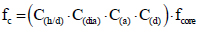
If, on the one hand, the definition of mechanical characteristics of steel (both structural and reinforcement bars) and masonry can be unequivocally defined according to original certificates and reference values, respectively, on the other hand, the same concept cannot be stated with reference to concrete, given that its strength is strongly influenced by several aspects. Indeed, compressive tests of concrete samples taken from the same building usually return very heterogeneous results. Moreover, an additional significant variance is represented by the interpretation of test outcomes, namely in the definition of the effective cylindrical compressive strength (fc) of the samples starting from the test result (fcore). In this context, many studies and methods are present in literature, as well as in the national codes. In this activity, the calculation criteria provided in [19], and reported in Eq. (1) has been adopted.
 |
(1) |
In Eq.(1):
- C(h/d) is the corrective coefficient accounting for height-to-diameter ratio of the sample (h/d) different from standard value 2, equal to C(h/d)=2/(1.5+d/h);
- C(dia) is the corrective coefficient related to the sample diameter, which is 1.06, 1.00 and 0.98 in case of d equal to 50, 100 and 150 millimetres, respectively, and linearly interpolated for intermediate values;
- C(a) is the corrective coefficient to adopt in the case of reinforcement steel elements included in the sample and it assumes values in the range 1.03÷1.13 according to steel bar diameters;
- C(d) is the corrective factor accounting for the noise of the sample due to extraction operations and can be assumed C(d)=1.20 and C(d)=1.10 in case of fcore<20MPa and fcore>20MPa, respectively.
Once that the cylindrical strength fc is determined, the corresponding cubic strength Rc is evaluated according to Eq.(2).
 |
(2) |
For the sake of brevity, in the following sections some considerations about the elaboration of the test outcomes and the characteristic strengths adopted for each building are reported, instead of the values arisen from each test.
3.1.2.2. Mechanical Characterization of [HB] Materials
Since for the buildings of [HB] original design documents were available, extended in-situ tests were carried out. It is worth noticing that in general the definition of the investigation plan has to respond to two main key needs: the preservation of the existing structures by executing as less as possible destructive tests, and the ensuring of the ordinary functionality of the medical facility during the extraction of material samples.
In particular, the first investigation plan has been defined hypothesising a good homogeneity of the results, and therefore a reduced number of tests, compared to the dimensions of the buildings, has been set. Definitively, 177 compressive tests on concrete samples and 49 tensile tests on reinforcement elements have been executed.
As far as the concrete is concerned, the homogeneity check has been carried out by analysing the data distribution respect to the declared value in the design phase (Rck=25MPa). Hence, strength ranges have been defined considering the standards provided in the Italian code for new buildings, which considers acceptable a variance of ±3.5 MPa for the characteristic value. In particular, starting from the mean value obtained for all units of [HB] (Rcm=31.2 MPa), the intervals were automatically determined. In Fig. (17) the distribution analysis for all units of [HB] is provided.
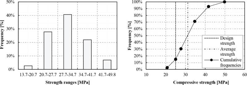
In the above graphs, it is clearly shown the Gaussian distribution of the compressive strength obtained with the destructive tests, as well as that the original design cubic strength (i.e., 25 MPa) resulted overcame in about 85% of cases. Moreover, can be asserted that 41%, which is the frequency obtained for the range containing the average value, is surely an acceptable value in order to justify the homogeneity of the material. According to these statements, it has been considered reasonable to adopt a characteristic strength equal to those foreseen in the designing phase, i.e. Rck=25MPa. Such an assumption has been even more corroborated by comparing the distributions obtained unit by unit. The additional analyses, which are not reported here for the sake of brevity, always returned values less than 20% of the cumulative frequencies at the original design value.
It is worth specifying that the so-defined strength of the concrete represents a conservative assumption and does not result in fully complying with both the Italian code and Eurocode 8, which suggest to adopt the average strength as a characteristic value. Nevertheless, such an assumption is in strong contradiction with the standards regarding a new building, for which the characteristic strength must be assumed less than the 5% fractile (hence overcame in 95% of cases). Moreover, in both new and existing buildings, the characteristic strength is reduced by means of the partial safety factor, which in the case of concrete is γc=1.5. Finally, in the sole case of existing structures, the obtained strength value must be reduced according to the level of knowledge and, thus, the confidence factor. Hence, since the codes are based on the semi-probabilistic methods, it could be asserted that the level of safety of new buildings, with such an approach, could result higher than those foreseen for existing ones, especially in the case of the maximum level of knowledge. In the meanwhile, with reference to the concept of homogeneity of the material, according to which the number of destructive and non-destructive tests can be reduced, a method aimed at defining in a close form the suitability of such an approach is still missing in the Italian code. Hence, in this sense, current codes for existing buildings would need to be revised or at least extended.
On the other hand, with reference to reinforcement bars, it is worth noticing that, being steel an industrialized product already since the construction periods of the investigated structures, its mechanical characteristics were ascertained in production plants. Hence, a significant dispersion of the results arising from tensile tests have not been obtained. In particular, in the buildings of [HB], the presence of Aq42, FeB2 and FeB44 steels has been surveyed from original design documents. Aq42 and Feb22 steels can be traced back to the same material quality referred to as smooth bars, despite regulated by two different codes: Circular n. 1472 of 1957 [20] and Ministerial Decree of 30/05/1972 [21], respectively. Hence, a single type of steel has been considered. On the other hand, FeB44 steel refers to improved-adherence bars, and again it is standardized in [21].
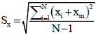
The design values and the yield strengths adopted for the cases under consideration are summarised in Table 5, with also the standard deviations Sx of the tests, calculated according to Eq.(3).
 |
(3) |
Where:
- N is the number of tests;
- xi is the value of the yield strength obtained in the i-th test;
- xm is the average value of the tests.
| - | Yield Strength According to Past Codes [MPa] | Average Yield Strength fym [MPa] |
Standard Deviation Sx [MPa] |
| Aq42 – FeB22 | ≥ 220-230 | 383.3 | 42 |
| FeB44 | ≥ 440 | 458.5 | 21.4 |
According to the outcomes obtained in the investigation campaign, given also the good homogeneity of the results, the average yield strengths have been adopted as design values, namely 383.3 MPa and 458.5 MPa for Aq42-FeB22 and FeB44, respectively.
3.1.2.3. Mechanical Characterization of [DH], [AB] and [NB] Materials
The investigation campaigns that interested the [DH], [AB] and [NB] buildings have been also planned according to the minimum invasiveness principle and taking care to not interrupt the functionality of the structures. As far as the structural steel of [DH] is concerned, the investigation interested both elements and bolts. In particular, according to original design documents, a Fe37 was adopted for steel elements, which corresponds to the nowadays called S235 typology. Nevertheless, the tests (both destructive and non-destructive, with the latter adopted to define solely the ultimate strength ftu) returned average values higher than those corresponding to a better quality of steel (i.e. Fe44 or S275) but less than those of Fe52 (or S355): fym=327.3 MPa and ftum=451.5 MPa. Hence, considering the good homogeneity of the results, once again, obtained (standard deviation Sx=33.6 MPa), S275 steel has been adopted in the calculation, with: fyk=275 MPa and ftk=430 MPa. With reference to bolts and nuts, the Vickers tests always returned values higher than declared ones in design documents, namely class 8.8 with yield and ultimate strengths equal to fyb=640 MPa and fub=800 MPa, respectively. Hence, these characteristics for the structural checks have been adopted.
To define the mechanical characteristics of the tuff masonry of [NB], a double flat jack test was executed. The test returned an elastic modulus and a compressive strength very close to the mean value defined in the table C8.5.1 of the 2019 Circular [12], hence the following parameters have been adopted:
- Compressive strength fm= 2.60 MPa;
- Shear strength τ0=0.06 MPa;
- Elastic Modulus: E= 1410 MPa;
- Tangential Modulus: G= 410 MPa
To determine the strengths of existing concrete and reinforcement steel, similar considerations to those stated for [HB] have been assumed in the other buildings. In particular, the homogeneity of the test results has been checked for each building, following the same procedure mentioned in the previous sub-section. In general, for [DH] the compressive tests on concrete specimens confirmed the declared class of concrete (C20/25 with Rck=25 MPa). With reference to buildings for which original design documents were missing, instead, similar results have been obtained for [AB] (Rm=25.3 MPa), while in [NB] the compressive tests returned a significantly higher average strength of the concrete (Rm=34.2 MPa). On the contrary, the tensile strengths obtained by tests on reinforcement steel bars resulted quite homogeneous, ranging from 426.3 MPa to 444.3 MPa for all buildings. Hence, the design and the average values have been adopted for concrete compressive strength and steel tensile strength, respectively, guaranteeing a good safety margin accordingly to the adopted confidence factor, which was assumed equal to 1.00 even in the absence of original design documents. A summary statement of the adopted strength compared to the original design values is provided in Table 6, where for the number of tested data references to Table 4-6 can be made.
3.2. Structural Modelling
3.2.1. FEM Models Geometry
The structural capacity of investigated buildings, for both seismic forces and vertical actions, has been analysed by means of numerical models implemented in Sismicad, which is commercial software for the structural calculation based on the Finite Element Method theory.
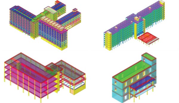
With reference to r.c. elements, frames have been modelled as mono-dimensional elements (hereinafter stated as beams, for both horizontal and vertical elements), while the presence of walls has been introduced in the models by means of 4-node shell elements. As far as structural steel elements are concerned, again, beams have been adopted, taking care to release the extremity bending moment in the horizontal elements to account for the hinge connections. Finally, for the masonry structure, a typical equivalent frame modelling has been used, with beam elements for piers and spandrels and rigid offset simulating their connections. In Fig. (18), the pictures of the implemented numerical models are shown.
Since the condition of a concrete slab thicker than 5 cm was always guaranteed, the horizontal structures have been considered as rigid diaphragms, after sensitive analyses that returned similar outcomes in both deformable and undeformable conditions. The stiffness contributes of partitions and infill walls have been neglected, while their masses have been accounted for by means of external loads. Finally, the foundation systems, given the sufficient stiffness and the geotechnical characteristics of the underlying grounds, have been always simulated by introducing total constraint conditions at the base nodes of the models.
3.2.2. Load Definition
As far as the applied loads are concerned, they have been defined according to the Italian and European code provisions. In particular, other than structural and non-structural permanent actions, superimposed live loads, depending on the use of the various structures, and snow have been considered. Hence, in Table 7 a summary of the adopted values of vertical live loads are provided for each investigated unit, where are also mentioned the corresponding categories as defined in the Italian Standards for the constructions.
| - | Concrete | Reinforcement Steel | |||
| - | Original Design Compressive Strength Rck [MPa] | Average Compressive Strength Rm [MPa] | Type of Declared Steel | Yield Strength according to Past Codes fyk [MPa] | Average Yield Strength fym [MPa] |
| [DH] | 25 | 25.8 | Feb 32k | ≥320 | 434.7 |
| [AB] | - | 25.3 | - | - | 426.3 |
| [NB] | - | 34.2 | - | - | 444.3 |
| - | - | Areas Considered with the Relative Load | |||
| Category | Live Load | [HB] | [DH] | [AB] | [NB] |
| Cat. A (residential use) |
2.00 kN/m2 | Hospitalization rooms | - | - | Residential areas |
| Cat. B.2 (offices opened to the public) | 3.00 kN/m2 | Surgeries and laboratories | Surgeries and laboratories | Offices opened to the public | - |
| Cat. C.1 (susceptible to crowding areas) | 3.00 kN/m2 | Dining area | - | Boardroom | |
| Cat. C.2 (susceptible to crowding areas) | 4.00 kN/m2 | Waiting areas | Waiting areas | - | - |
| Cat. C.3(susceptible to crowding areas) | 5.00 kN/m2 | Entrance halls | Entrance halls | - | - |
| Cat. G (veichular ramps) |
5.00 kN/m2 | Vehicular ramp | - | - | - |
The vertical loads have been combined according to the so-called fundamental combination, which has been adopted for checking the structures in the Ultimate Limit State conditions and foresees the amplification of the loads with partial safety factors and combination coefficients.
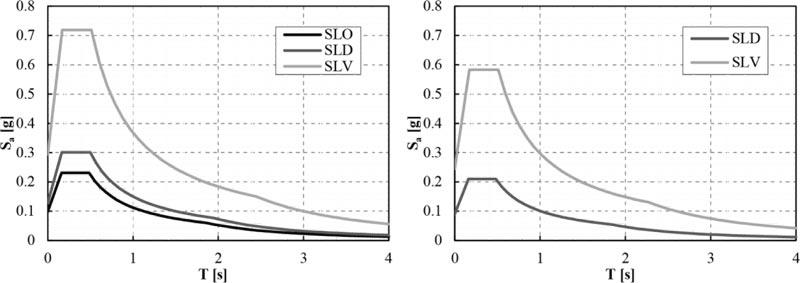
With regards to the seismic action, it has been defined as a function of the site, the soil characteristics, the exceeding probability depending on the considered limit state (PVR), and the use coefficient of the structures according to their strategic importance (CU), as well as the nominal life VN, which has been considered equal to 50 years for all buildings. Hence, it is worth noticing that the investigated structures being almost all considered as strategic, a CU=2 have been always adopted except for [NB], to which CU=1 has been assigned. Furthermore, for the latter cases, the solely Life Safety (SLV) and Damage Limit States (SLD) have been considered (PVR=10% and PVR=63%, respectively), while for the strategic units also the attainment of the Operatively (SLO) one (PVR=81%) has been investigated. Graphs of the adopted response spectra are plotted in Fig. (19).
3.2.3. Structural Check Criteria
The vertical checks have been executed based on linear analysis. On the other hand, the numerical analyses and the relative seismic checks to define the risk index (IR) have been carried out by means of non-linear static analyses (Pushover), assuming both mass and modal proportional distribution of loads applied in the centre of the masses of each story. The risk indexes have been expressed in terms of both peak ground acceleration (PGA) and return period (TR). Hence, the checks have consisted in comparing the displacement capacity of each structure or unit, obtained assuming the structure behaviour as a system having a Single Degree of Freedom (SDOF) and thus bi-linearizing the relative force-displacement curve, with the displacement demand arisen from the elastic displacement response spectra related to each specific limit state, opportunely reduced to account for the ductility of the structures.
In particular, the bilinear curves have been obtained from the numerical force-displacement curves, by assuming: i. a stiffness of the initial branch equal to those corresponding to the 60% of the maximum lateral force; ii. an ultimate displacement corresponding to those for which a decreasing up to 20% of the maximum lateral force occurs; iii. a maximum force obtained by equalling the areas under the real and the bilinear curves.
Hence, once that the elastic response spectrum (Spectral elastic Acceleration Saeversus period T) has been defined, it is converted and plotted in the Spectral elastic Acceleration versus Displacements (Sde) plan (Acceleration Displacement Response Spectra –ADRS) by means of Eq. (4).
 |
(4) |
Then, by adopting the so-called N2 method implemented by Fajfar [22, 23], the demand spectrum (Saversus Sd) is evaluated according to Eq. (5):
 |
(5) |
where, μ is the ductility factor defined as the ratio between the maximum and yielding displacement of the bi-linearized curve and Rμ is the reductive factor due to the ductility of the SDOF system, which could be calculated according to Eq.(6) [24]:
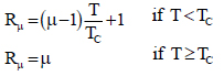 |
(6) |
Hence, the demanded displacement is evaluated by estimating the so-called performance point, which is obtained by the intersection between the capacity spectra (i.e., the bi-linearized Acceleration versus Displacement curve) and the reduced response one. On the other hand, the capacity is evaluated by checking the attainment of the relative limit state, depending on the material of the structures, as better explained in the following. It is worth specifying that the seismic-resistant structure of the [DH] building consists of concrete cores. Indeed, being the steel beams connected by means of hinge nodes to the columns, this latter assumes an inverted-pendulum behaviour, which is characterized by very low lateral stiffness with respect to concrete elements. Moreover, regarding [NB] building, the operatively limited state has not been considered, given its non-strategic function. Thus, each limit state for r.c. structures have been considered attained if the following conditions have occurred:
- Operatively Limit State (SLO): drift (relative displacement between two consecutive floors) higher than 2/3·5.0‰·h (story height);
- Damage Limit State (SLD): drift higher than 5.0‰·h;
- Life Safety Limit State (SLV): i. for ductile collapse mechanisms, total chord rotation θ of a floor higher than 3/4·θu (ultimate chord rotation); ii. for brittle collapse mechanisms, shear failure or collapse of unconfined nodes.
Such conditions remain valid for [NB] concrete portion, while for the masonry one, the attainment of the limit states has been considered under the following conditions:
- Damage Limit State (SLD): lower displacement between those corresponding to the maximum force and those corresponding to a drift higher than 2.0‰·h;
- Life Safety Limit State (SLV): displacement equal to 75% of those at the Collapse Limit State (SLC). The SLC displacement is defined as the lower between those corresponding to a residual base shear equal to 80% of the maximum shear and those corresponding to the attainment of the maximum angular displacement in each masonry pier relevant for the global stability of the structure.
Finally, it is worth mentioning that the post elastic behaviour of r.c. and steel elements is accounted for by means of fiber elements. In particular, the stress-deformation state of a generic section of an element is obtained by integrating the uniaxial law of each fiber composing the section. On the other hand, the masonry elements have been considered with the typical elastic perfectly-plastic behaviour until the attainment of limit drifts depending on the type of crisis (flexural or shear).
3.3. The Obtained Results
3.3.1. General
In this section, the main results obtained by means of numerical analyses are summarised. Given the high number of performed analyses, for the sake of brevity here, the attention is focused on the outcomes arisen from only one of the investigated structures. Indeed, in addition to structural checks against vertical loads, 32 analyses have been performed for each considered unit in order to evaluate their seismic capacity. In particular, for each distribution of horizontal loads (mass and modal proportional), the two main directions have been combined with the relative eccentricities (even in this case assuming both signs) in order to account for the uncertainties related to the real position of the centre of masses. Hence, in this section, unit C of the [HB] is deeply analysed, since its dimensions and construction features are considered representative of the other units, as well as of major interest. Nevertheless, the results obtained for the other cases are also provided.
3.3.2. Structural checks in case of vertical loads
As far as the vertical loads are concerned, the numerical analyses showed, in the whole, a good capacity of the all investigated structures. Indeed, the structural checks always returned positive outcomes, despite in some cases safety indexes close to one, defined as capacity-to-demand ratios, have been obtained. In Fig. (20) the safety indexes of the unit C of [HB] due to vertical loads (i.e. fundamental combination) are plotted with a contour view.
It is possible to observe that in almost all beams, the work rates resulted close to the unit due to shear stresses. Nevertheless, these results are surely acceptable in order to guarantee operatively the structures in case of standard load conditions. In addition, the obtained results have been further corroborated by means of six load tests on slabs, which always showed a good structural behaviour.
3.3.3. Structural checks in case of seismic loads
In the present study, the risk indexes have been expressed in terms of both PGA and TR. In the first case, the comparisons between demand and capacity are made directly by a graphical method in the ADRS plane, and the respective risk index IR(PGA) is calculated by operating a simple ratio between the two values, namely capacity-to-demand ratio. Nevertheless, the current 2018 Italian code proposes indexes in terms of the return period, which is considered a more representative risk parameter. Indeed, with the new approach, the scale of risk assessment results very different from the one commonly used previously in terms of PGA, mainly due to the concave shapes of the response spectrum in terms of accelerations (or pseudo-accelerations) versus periods. Hence, despite it is possible to associate a return period to each level of acceleration, the risk index in terms of the return period, can be estimated according to Eq.(7):
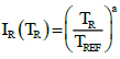 |
(7) |
Where TR is the return period related to the attainment of a specific limit state (i.e., the capacity of the structure), TREF is the return period with the exceeding probability typical of the considered limit state (i.e., the demand) and a is a coefficient adopted to obtain a scale of risk compared with the previous one. According to a statistical analysis of the national hazard curves, the coefficient a could be assumed equal to 0.41 [25].
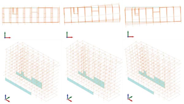
As has been aforementioned, the results obtained for unit C of the [HB] are deeply analysed in this section. In Fig. (21), the dynamical characteristics of the model arisen from a modal analysis, which has been adopted for the modal proportional distribution of loads, are shown.
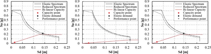
In Fig.(22), the checks in the ADRS plane related to the SLV conditions are plotted, while in Table 8, the obtained seismic risk indexes for each collapse (or damage) mechanism of unit C are summarised.
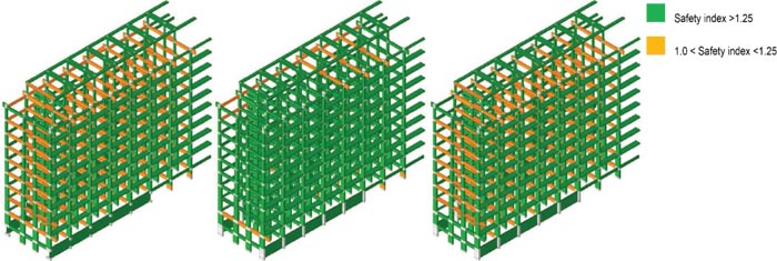
The results put into clear evidence the high seismic vulnerability of the investigated structure, being the minimum seismic risk index in terms of return periods equal to 0.197. More in detail, as far as the Operatively and Damage limit states are concerned, the structural checks are not satisfied, even if risk indexes quite close to the unit have been obtained. On the contrary, with reference to the structural checks at SLV conditions, the structure exhibited significant deficiencies, whatever the collapse mechanism was considered. In order to better understand the evolution of the considered collapse mechanisms, in Fig (23) the seismic risk indexes for each structural element and related to the different collapse criteria at the SLV are plotted in a contour view.
| Limit State | Criterion | PGA [g] | TR [year] | IR(PGA) | IR(TR) |
| SLO | Drift | 0.088 | 50 | 0.904 | 0.927 |
| SLD | Drift | 0.123 | 93 | 0.959 | 0.967 |
| SLV | Shear failure (beams) | 0.040 | 18 | 0.137 | 0.197 |
| Node collapse | 0.053 | 24 | 0.182 | 0.221 | |
| Flexural failure (beams) | 0.058 | 26 | 0.197 | 0.229 |
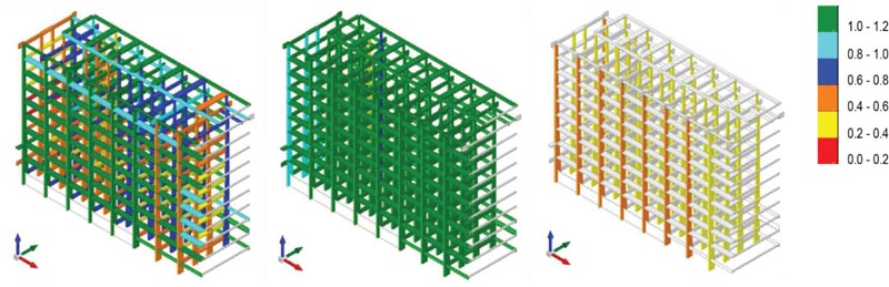
In particular, among the collapse mechanisms of SLV, it is interesting to note that the mechanism corresponding to the lower index is the shear failure of the external beams of 5th and 6th stories. Moreover, columns are also affected by a relevant shear deficiency, especially the ones close to the staircases. Similarly, with reference to node collapse, the main seismic issues have been obtained in the staircase proximity, despite a lack of capacities that have been widely obtained. Finally, with regard to ductile (i.e., flexural) collapses, although some columns present a bad capacity with respect to the demand, the largest portion of elements resulted verified against the design seismic loads.
It is worth noting that the structural problems affecting unit C of [HB] are typical for buildings erected between ’50s and ’60s of the last century. This aspect appears even more relevant considering that the first Italian rigorous standards (i.e., based on scientific knowledge rather than empirical criteria) in the field of seismic engineering dates back to 1974 [26].
Indeed, most of the buildings analysed in this study, returned a significant seismic vulnerability, as it is shown in Table 9 and Fig. (24), where the seismic risk indexes are summarised for each considered limit state. For convenience of the reader, only the most penalizing collapse mechanism has been considered for the SLV.
| Structural Unit | Limit State | Criterion | PGA [g] | TR [Year] | IR(PGA) | IR(TR) |
| Unit A [HB] | SLO | Drift | 0.058 | 26 | 0.591 | 0.709 |
| SLD | Drift | 0.079 | 41 | 0.619 | 0.691 | |
| SLV | Shear failure (beams) | 0.031 | 14 | 0.106 | 0.178 | |
| Unit B [HB] | SLO | Drift | 0.058 | 26 | 0.591 | 0.709 |
| SLD | Drift | 0.099 | 62 | 0.777 | 0.819 | |
| SLV | Shear failure (beams) | 0.009 | 4 | 0.030 | 0.106 | |
| Unit D [HB] | SLO | Drift | 0.018 | 8 | 0.182 | 0.437 |
| SLD | Drift | 0.036 | 16 | 0.278 | 0.470 | |
| SLV | Node collapse | 0.074 | 36 | 0.252 | 0.261 | |
| Unit E [HB] | SLO | Drift | 0.053 | 24 | 0.545 | 0.686 |
| SLD | Drift | 0.074 | 36 | 0.576 | 0.655 | |
| SLV | Node collapse | 0.018 | 8 | 0.061 | 0.141 | |
| Unit F [HB] | SLO | Drift | 0.027 | 12 | 0.273 | 0.516 |
| SLD | Drift | 0.053 | 24 | 0.417 | 0.555 | |
| SLV | Node collapse | 0.036 | 16 | 0.121 | 0.187 | |
| Unit G [HB] | SLO | Drift | 0.099 | 62 | 1.016 | 1.012 |
| SLD | Drift | 0.132 | 107 | 1.029 | 1.024 | |
| SLV | Shear failure (beams) | 0.022 | 10 | 0.076 | 0.155 | |
| [DH] | SLO | Drift | 0.093 | 55 | 0.952 | 0.964 |
| SLD | Drift | 0.136 | 115 | 1.066 | 1.055 | |
| SLV | Shear failure (walls) | 0.044 | 20 | 0.152 | 0.205 | |
| [AB] | SLO | Drift | 0.053 | 24 | 0.545 | 0.686 |
| SLD | Drift | 0.083 | 45 | 0.652 | 0.718 | |
| SLV | Shear failure (beams) | 0.031 | 14 | 0.106 | 0.178 | |
| [NB] masonry | SLD | Drift | 0.053 | 24 | 0.603 | 0.740 |
| SLV | Drift | 0.093 | 55 | 0.382 | 0.413 | |
| [NB] r.c. | SLD | Drift | 0.08 | 45 | 0.943 | 0.958 |
| SLV | Node collapse | 0.044 | 20 | 0.182 | 0.273 |
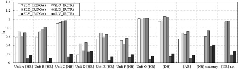
In the whole, the results reveal a lack of seismic capacity with respect to the demand of the investigated structures. More precisely, even in the case of less significant seismic actions (i.e., in SLO and SLD conditions), the seismic risk indexes resulted in most cases less than 1. As far as the SLV conditions are concerned, the so-defined strategic buildings, all returned a seismic risk index less than 0.26, in terms of both PGA and return period. Nevertheless, [NB] also exhibited a significant vulnerability, especially for the r.c. portion, despite less demand due to the ordinary use of the construction.
In addition, with reference to units of [HB], possible pounding phenomena between adjacent structures could occur under seismic loads, as well as the loss of supports in case of Gerber connections. Moreover, for each investigated building, the so-called unquantifiable vulnerabilities, both structural and non-structural, have also been detected. In particular, such problems are mainly related to the state of conservations of the buildings, as largely advanced degrade phenomena of the r.c. structures, i.e., oxidation of steel bars and consequent detaching of the concrete coverage, have been detected. Other similar problems, which could lead to early significant damage or unusability, are represented by the anchorage of both plant systems and shelves, double-leaf infills without transversal connections, plaster degrades, and humidity issues, (Fig. 25).
4. DISCUSSION
4.1. Perspectives for Strengthening Interventions
4.1.1. Qualitative Description of the Possible Strengthening Interventions
The last phase of the study provided the definition of possible strengthening interventions to guarantee the functionality of the structures also in case of seismic events. It is worth noting that the possible strengthening measures proposed in this phase were mainly aimed at preliminary estimating the retrofitting costs, rather than designing the specific interventions, for which an additional and extensive detailed activity would need. In particular, based on the outcomes obtained by the structural assessment, strengthening interventions aimed at improving the seismic capacity of the structures have been hypothesized in order to increase the seismic risk indexes to a value in the range of 0.80-0.85, which represents a minimum recommendable threshold for strategic buildings, like the ones considered in this study. To this purpose, as a basic retrofitting strategy, supplementary structural elements have been introduced in the structural system, which should be able to counteract about 60-65% of the total seismic story shear forces. Moreover, interventions aimed at reducing the so-called unquantifiable vulnerability have also been suggested.
Some of the main suggested structural interventions for the examined buildings are listed in the following:
- Insertion of dissipative steel diagonals or V-bracings for r.c. structures in combination with retrofitting of beam-to-column nodes and beams (with FRP) and columns (with steel jacketing);
- Insertion of dissipative steel diagonals or V-bracings for steel structures with retrofitting of beam-to-column nodes, beams and columns;
- Enlarging of existing r.c. walls;
- Realization of new r.c. walls;
- Enlarging of existing r.c. beams;
- Retrofitting of existing r.c. beams by means of FRP applications;
- Retrofitting of existing r.c. columns by means of jacketing of steel elements;
- Demolition and reconstruction of existing joints between adjacent buildings;
- Realization of new steel beams;
- Realization of new r.c. frames;
- Retrofitting of connections between steel beams and r.c. cores;
- Realization of new tuff masonry walls;
- Realization of reinforced plaster on both sides of masonry walls.
In Table 10, a summary of the structural interventions applied for each structural unit is provided.
The suggested structural interventions were also aimed at reducing the so-called unquantifiable vulnerabilities, namely those not detectable by means of numerical models. The most relevant of these problems was surely represented by the double-leaf infills, which usually exhibit out-of-plane collapse mechanisms in case of seismic events. To overcome this issue, the insertion of transversal drills consisting of masonry bricks, as well as the realization of anti-overturning systems by means of reinforcement strips (e.g. GFRP), has been considered. In addition, updates of the existing installation systems were also prescribed by means of suitable and flexible connections in order to guarantee their functionality also under seismic load conditions. Similarly, appropriate anchorages of the shelves to the walls were planned. Moreover, widespread interventions aimed at preserving and reducing the degradation of the existing r.c. structures were also foreseen.
4.1.2. Retrofitting Cost Estimations
The strengthening interventions qualitatively described in the previous section allowed the estimation of costs for upgrading the existing structures. Such a phase is significantly relevant for decision-making processes since, by means of a cost-benefit analysis, a complete reconstruction could often result more convenient than diffused interventions for ancient buildings such as the ones under consideration. Hence, a comparison between the retrofitting costs and those corresponding to the realization of new buildings is also provided by considering parametric costs typical of the investigated structures according to official reports and documents in terms of cost incidence per square meter of story.
In Table 11, a summary of the estimated costs for retrofitting the existing structures in order to achieve seismic risk indexes, as defined by means of Eq.(7), of at least 0.80 is provided for each unit.
| - | [HB] | [DH] | [AB] | [NB] | ||||||
| - | A | B | C | D | E | F | G | |||
| Bracing members (r.c.) | x | - | x | - | x | x | x | - | x | - |
| Bracing members (steel) | - | - | - | x | - | - | - | x | - | - |
| Enlarging of existing r.c. walls | x | x | x | - | x | - | x | x | x | - |
| Realization of new r.c. walls | x | x | x | - | x | - | x | x | - | - |
| Enlarging of existing r.c. beams | - | x | - | - | - | - | - | - | - | - |
| Retrofitting of existing r.c. beams (FRP) | - | - | - | x | - | x | - | - | - | x |
| Retrofitting of existing r.c. columns | - | x | x | - | x | x | x | x | - | x |
| Demolition and reconstruction of existing joint | x | x | x | x | x | x | x | x | - | x |
| Realization of new steel beams | - | - | - | x | - | - | - | - | - | - |
| Realization of new r.c. frames | - | - | x | x | - | - | x | - | - | - |
| Retrofitting of connections between steel beams and r.c. cores | - | - | - | - | - | - | - | x | - | - |
| Realization of new tuff masonry walls | - | - | - | - | - | - | - | - | - | x |
| Realization of reinforced plaster | - | - | - | - | - | - | - | - | - | x |
| - | [HB] | [DH] | [AB] | [NB] | ||||||
| A | B | C | D | E | F | G | ||||
| Total retrofitting costs [€/1000] | 3500 | 6750 | 7100 | 1450 | 3615 | 1755 | 7700 | 8155 | 1250 | 375 |
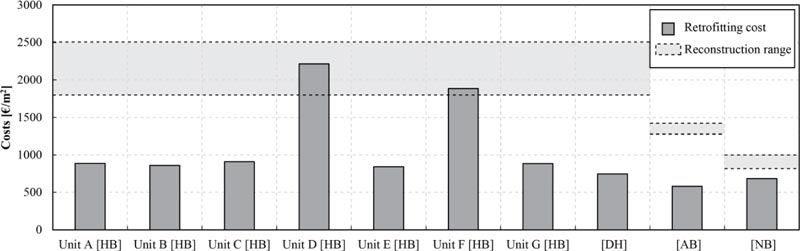
| Cost per square meter [€/m2] | 887.2 | 859.3 | 910.3 | 2213.7 | 842.7 | 1887 | 885.1 | 747.5 | 581.4 | 685 |
The so-estimated costs include both structural and non-structural interventions, while disregard the labour cost, as well as design and tax amounts. Moreover, a weighted average has been considered for [HB] buildings, which leads to define a total retrofitting cost of 3’1855’000 € and a cost per square meter of story of 932 €/m2. It can be stated that, according to this estimation, the Hospitalization Building, due to its structural complexity and strategic functionality, revealed the need of the most expensive interventions.
Hence, the costs expressed in terms of incidence per square meter have been compared to parametric costs available in official documents, which are related to the realization of new buildings and, again, disregard additional costs. In particular, for [HB] and [DH] reference to [27] has been made, which is a relevant report including theoretical construction costs for hospitals. In particular, by assuming a mean value of the values proposed in this document, a cost in the range of 1800-2500 €/m2 for the realization of new buildings has been obtained. This value resulted comparable to those obtained for subunits D and F of [HB]. In this regard, it is worth mentioning that these units present a low surface extension, as well as they should need relevant interventions aimed at avoiding interactions with other structures, which significantly engrave on the total cost. On the contrary, by comparing such a value with the ones returning by the entire units [HB] and [DH], can be noted that it corresponds to about two and three times, respectively, with respect to upgrading costs of the existing structures.
As regards [AB], reference to [28] has been made, in which is assumed that the cost of realization of a new building with a rectangular plan for offices can be estimated ranging between 1300 €/m2 and 1450 €/m2. Hence such a value results strongly higher than those evaluated for upgrading the existing structure. Finally, [NB] has been considered on a par with residential buildings. Hence, again according to [28], the price for the realization of a new building can be estimated in the range of 800÷1000 €/m2, which resulted higher than the evaluated retrofitting cost.
In the whole, the reliability of the planned possible interventions has been widely confirmed, being the reconstruction costs always higher than retrofitting ranges. A summary of the obtained results is provided in the histogram of Fig. (26), where the retrofitting and reconstruction costs per square meter are compared.
CONCLUSION
The seismic safety of strategic structures, such as hospitals, is a noteworthy issue in Italy, given the notable seismic hazard affecting this zone, as well as the ancientness and deficiencies of existing buildings. In this context, this study dealt with the vulnerability assessment procedure carried out on the medical facility “G. Pascale” in Naples, which is one of the most important hospitals in South Italy.
Hence, a deep description of the adopted procedure has been provided, with a particular focus on the mechanical characterization of the in situ materials. In particular, the issues concerning the application of the current Italian code and also Eurocode 8, have been deeply analysed, providing a possible application aimed at optimizing the number of destructive tests and reducing the uncertainties affecting the real strengths of existing materials, as well as showing the necessity of more detailed dispositions in the current standards.
Based on such assumptions and a detailed geometric survey, non-linear static analyses have been performed, in order to quantify the demand-to-capacity ratios of the investigated structures under seismic load conditions. By means of the pushover analyses, whose calculation methodology has been presented in detail, all the investigated structures returned a significant structural deficiency to face the design seismic actions, highlighting the need for structural interventions aimed at enhancing their seismic performances. Finally, retrofitting interventions have been suggested and qualitative cost analysis has been performed, considering both structural and non-structural problems, providing as output the reliability and the economic convenience of retrofitting interventions.
The presented case study showed an unacceptable structural vulnerability in case of the seismic event of the investigated medical facility, also given its strategic function in case of emergency, highlighting the strong necessity to realize significant interventions. Since the structures present typical features of buildings realized in the last century before the enacting of specific anti-seismic codes, the final results could be easily extended to similar public buildings, which, especially in the Italian territory, too often play strategic functions without an adequate level of seismic safety. In this context, and with particular reference to hospital buildings, a national-scale approach aimed at prioritizing the necessary interventions is surely suitable, given that nowadays in Italy the total number of public medical facilities amounts to about 500 units.
CONSENT FOR PUBLICATION
Not applicable.
AVAILABILITY OF DATA AND MATERIALS
Not applicable.
FUNDING
None.
CONFLICT OF INTEREST
The authors declare no conflict of interest, financial or otherwise.
ACKNOWLEDGEMENTS
The present study has been developed within the activity commissioned by National Cancer Institute “G. Pascale Foundation” of Naples to the Department of Architecture and Industrial Design of the University of Campania “Luigi Vanvitelli”, which aimed at supervising and validating the activity of the Joint Venture formed by the engineering firms AIRES Engineering srl (leader team) and ALL Ingegneria, which was in charge to develop the professional service presented in this paper.

