All published articles of this journal are available on ScienceDirect.

Behavior Hollow Concrete Reinforced Slab with The Utilization of Polyvivyl Chloride Pipe as a Cavity
Authors Info & Affiliations
Abstract
Background:
Slab weight can be reduced by replacing the amount of concrete in the tensile area with the utilization of modification polyvinyl chloride pipe as cavity without reducing the flexural strength because the nature of concrete is weak against tensile strength.
Methods:
This research with the experimental method using static load. The setting of tools refers to the American Society for Testing and Material E 2322, bending analysis is used moment coefficient method, deflection by applying Ugural and Navier method, and shear analysis using Indonesia National Standard 03-2847-2019.
Results:
The specimens consist of solid plates with a thickness of 140 mm and hollow plates with a thickness of 140 mm and 159 mm. The maximum load capacity solid plate is 410.642 kN, while the hollow plates (140 mm) is 335.18 kN, and for the hollow plates 159 mm is 396.257 kN. The solid plate’s stiffness is 16.321, the hollow plates 140 mm is 14.787 and the hollow plate 159 mm is 24.194, while the ductility is 1.993 on solid plate, the hollow plate 140 mm is 2.014, and the hollow plate 159 mm is 1.862. The solid plate’s damage is flexural, while the two hollow plates are a combination of bending and shear damage. The crack pattern on the solid plates is flexible, while the crack pattern on both hollow plates is a combination of flexural cracks and shear cracks.
Conclusion:
The use of modified polyvinyl chloride pipes can be recommended in the structure of the plate. There is a small, insignificant difference in the flexural behaviour between the solid plate and hollow concrete reinforced slab with the utilization of Polyvinyl Chloride.
1. INTRODUCTION
Hollow Core Slab Technology is a technology that seeks to improve the efficiency of the reinforced concrete slab structure [1]. The technology aims to reduce the structure's weight and save concrete material. The limitations of the Hollow Core Slab as one-way slabs have spurred various studies to find reinforced concrete slabs that are lightweight and can behave as two-way slabs [2]. In 1990, Joergen Breuning [3] invented a spherical hollow plate called the Bubble Deck, produced with a thickness of 230 - 600 mm. This type is 30 - 40% lighter than solid slabs of the exact dimensions and generally behaves like solid concrete slabs. The ball-style hollow concrete slabs can distribute better than the Hollow Core Slab because the three-dimensional shape of the structure's cavity can cause the flow style to work better [4].
Several researchers have developed alternative technology for hollow concrete slabs from 2003 to 2005. Aldejohann and Schnellencbach [5] investigated biaxial hollow slab where both types of the plate have a cavity in the concrete in the tensile area, reducing its weight. In 2009, Bayu [6] and Soeharno [7] conducted a hollow ball plate research with an in-site cast system. In 2013, Muizu [8] and Intansari [9] investigated a one-way hollow reinforced concrete slab with an in-site cast system utilizing empty bottles of water. With the holes located on the plates, the concrete volume used to reduce the cost of making concrete structures. When the volume of concrete used decreases, the need for cement as the primary material for making concrete will decrease to reduce CO2 emissions in the air [10].
Limited research and regulations on hollow reinforced concrete slabs and a patented minimum plate thickness factor, namely a bubble deck of 230 mm, encourage this research to obtain a slab structure that is easier in terms of implementation and low prices by using the even loading method on two-way plates and alternative material for modified pvc pipe.
The study's purpose was to determine the flexural behav- ior, ductility, stiffness, crack patterns, and shear that occurs due to uniform loading on the hollow concrete slab against solid reinforced concrete slabs [11]. The hollow reinforced concrete slab has the same thickness and volume as the solid reinforced concrete slab.
The moment coefficient method is used for bending analysis [12]. Deflection analysis is carried out by applying the Ugural method and the Navier method [13]. In general, Navier explains that the solution to thin flexure plates' bending contains the Fourier series for the load (p) and deflection (w). Meanwhile, the shear analysis is carried out using SK-SNI 03-2847-2019 [14].
The novelty from this experiment is the use of modified PVC pipes as cavity formers, is more efficient in distributing forces due to the three-dimensional geometric shape of the cavity structures and with a uniform loading simulation on the test plate and two-way plate analysis is able to resemble the existing loading conditions in the field.
The benefits expected from the analysis are obtaining savings using lighter concrete and slabs and finding out the effect of cavities on the slab structure's behavior.
2. LITERATURE REVIEW
A plate is a flat plane structure having a flat center plane first [15]. Then, it will bend after experiencing a perpendicular load or bending moment on it [16]. Reinforced concrete slabs consist of two systems, namely one-way and two-way system plates [17]. A two-way slab system can also occur in single and continuous span plates if the long span to short span ratio is less than two [18].
Hollow concrete plates include ceramic concrete, hollow core slabs, and biaxial hollow slabs. The shape of the ceramic concrete resembles a brick block, but the center is hollow. The hole has been calculated accurately to be used for floor slabs [19]. According to the results of Loading Test-II No LB/ BPPPU/001-12/ IX/99 06.09.99., the concrete ceramic will bend at loads above 500 kg/m2 [20]. Hollow core slabs are precast and prestressed concrete slabs that have elongated holes formed from special molds during fabrication [21]. Casting on the plate's surface (overtopping) and wire mesh reinforcement is needed to join the hollow core slab panels. Due to its shape as longitudinal panels, it can only be used for one-way floor slabs [22].
In the 1990s, Joergen Breuning [23] invented a spherical hollow concrete slab called the Bubble-Deck. The concrete slab's reinforcement consists of a fabricated reinforcement model where the upper and lower reinforcement clamps the hollow ball. Bubble-Deck can be made with a partially precast system, where the concrete casting at the factory is only done at the bottom of the slab so that it covers all the lower reinforcement. The rest is cast after Bubble-Deck, is at the installation site. Bubble-Deck can also be made with a fully precast system and without precast concrete layers. Bubble-Deck is produced in thicknesses of 230, 280, 340, 390, 450, 510, and 600 mm. In general, spherical hollow concrete slabs have the same bending behavior as solid concrete slabs [4]. The main difference between spherical hollow concrete slabs and solid plates is the shear resistance. The reduced volume of concrete will reduce the shear strenght, analysis of the shear strength of spherical hollow plates in DIN 1045-1 based on the distance between balls [5].
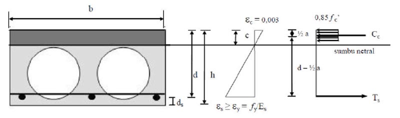
The distribution of stress and strain on a hollow spherical plate cross-section can be seen in Fig. (1). When the steel reinforcement has yield (fs = fy), the following equation applies.
 |
(1) |
If the strain of steel (Es) = 2.105 MPa and the compressive strength of the concrete fc '≤ 30 MPa then Mn = Ts (d - ½. A) = Cc (d - ½. A) = 0.85. f'c. b. a. (d - ½. a) Mu = Mn. Φ; Φ = 0.8
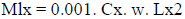
The analysis of the bending strength of two-way plates can be analyzed using the Moment Coefficient Method, the value of the moment in the short span direction (Mlx) and the moment in the long span direction (Mly) is sought on the two- way plate using the moment coefficient method.
In the Moment Coefficient Method, the value of the moment in the short span direction (Mlx) and the moment in the long span direction (Mly) are sought on the two-way plate using the coefficients.
 |
(2) |
For deflection analysis, the Navier and Ugural methods are used [24]. The direct planning method cannot be used because each specimen is only one span.
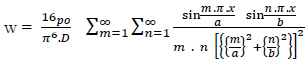
The Navier method uses a double sine Fourier series. The Navier method analyzes plates with loading patterns in the form of evenly static load (po) with joint support on all four sides [25]. The deflection equation for the even loading pattern is:
 |
(3) |
The equation for the moment in the short span direction is:
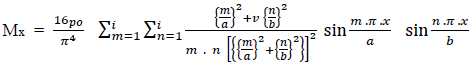 |
(4) |
The ductility factor of Navier for hollow plates is:
 |
(5) |
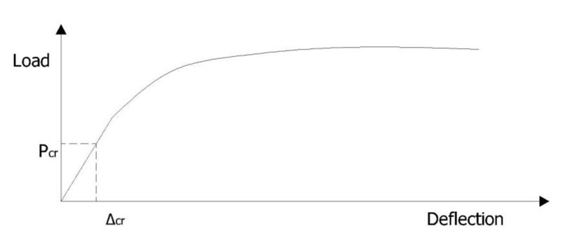
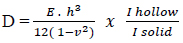
In 1987, Gere and Timoshenko [26] stiffness as the force required to produce a deflection of one unit (Fig. 2) using the following equation:
 |
(6) |
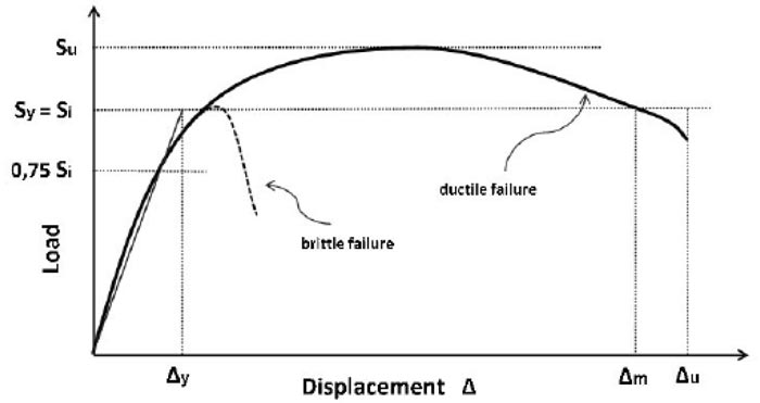
The structure is brittle if the structure is immediately damaged when the external load acting on the structure exceeds its elasticity strength or yield limit. Meanwhile, the structure is ductile if the structure does not immediately break down after crossing the elastic limit, but it shrinks up to a certain time limit and will be damaged if the plastic limit is exceeded. Equation of ductility:
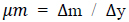 |
(7) |
The ductility of the reinforced concrete slab structure can be determined from the ratio of maximum deflection to yield deflection [27] (Fig. 3).
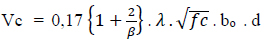
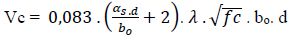
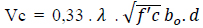
Damage to the plates can be caused by shear forces. Shear forces can occur due to concentrated loads or area loads. The concentrated load or area load that is held by the plate can cause shear stress in a surface around the load. In SK SNI 2847: 2019 article 22.6.1 6 [14], the calculation of the ability of a non-prestressed two-way plate to withstand shear forces, the smallest value is taken from the following three formulas:
 |
(8) |
 |
(9) |
 |
(10) |
3. RESEARCH METHOD
3.1. The Specimens
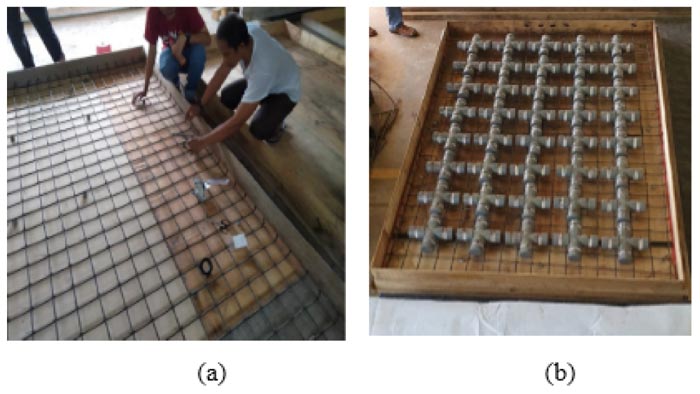
The plate variable to be studied is 3 plates, the first is a solid plate with dimensions of 2700 mm in length, 1800 mm in width, and 140 mm in thickness, symbolized by PP-1. The second plate is a hollow plate with PVC as a cavity forming with dimensions of 2700 mm long, 1800 mm wide, and 140 mm thick symbolized by PB-2, and the last plate is a hollow plate with PVC as cavity formers with dimensions of length 2700 mm, width 1800 mm and 159 mm thick, is symbolized by PB-3. Each PVC cavity used has a diameter of 760 mm, and the three plates use plain steel reinforcement with a diameter of 8 mm with a distance of 100 mm between the bars.
After the test object is at least 28 days old, it can be tested. Previously, the test concrete cylinder was tested to determine the compressive strength of the concrete. The even loading pattern is carried out by giving loads in the form of sandbags. Then on top of the sandbags, given a concrete plate then a steel holder is installed to distribute the load from the hydraulic jack to the concrete plate. It is expected that this loading pattern can resemble evenly distributed loading. The loading is carried out in stages until it reaches the plate capacity.
The variable to be analyzed is PP-1 as a solid plate with a thickness of 14 cm. The design of PP-1 is shown in Fig. (4) as follows:
PB-2 a hollow plate with PVC as a cavity maker with a thickness of 140 mm, and PB-3, a 159 mm thick PVC hollow plate. Each modified PVC cavity using a diameter of 760 mm and steel reinforcement with a diameter of 8 mm with a distance between the bars lengthwise and transverse is 100 mm. Details of the specimens in the analysis are shown in Table 1 as follows:
With the PVC cavity on the PB-2 hollow plate, the weight of the slab concrete is reduced to 86.17% of the weight of the solid plate with the same dimensions. PB-3 hollow plate has a higher “d” value than PP-1 hollow plate, but because PB-3 hollow plate is hollow, its weight is the same as the PP-1 plate. The amount of reduction in the percentage of concrete volume or the addition of the value “d” depends on the thickness of the slab.
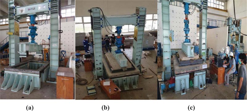
3.2. Setting of Tool
In this research, the specimen is supported by joint support along all four sides. The testing tool setting refers to ASTM E 2322, which is a two-way slab test with a uniform load simulation [28] (Fig. 5). The even loading pattern is carried out by giving loads in the form of sandbags, then on top of the sandbags, given a concrete plate then a steel holder is installed to distribute the load from the hydraulic jack to the concrete plate [29]. It is hoped that this loading pattern can resemble evenly distributed loading (Fig. 6). The loading is carried out in stages until it reaches the plate capacity [30].
| Plate | Dimension (mm) |
Ø Cavity (mm) |
Distance between cavities (mm) | Dead weight per 1 m2 (kg) |
ρ (%) | d (mm) | Concrete volume (%) |
|---|---|---|---|---|---|---|---|
| PP-1 | 2750x1800x140 | - | - | 1164,405 | 0,403 | 112,4 | 100 |
| PB-2 | 2750x1800x140 | 76 | 24 | 1003,173 | 0,403 | 112,4 | 86,17 |
| PB-3 | 2750x1800x159 | 76 | 24 | 1164,405 | 0,345 | 131,4 | 100 |
4. RESULTS AND DISCUSSION
4.1. Agregate Characteristic Test
Agregate characteristic test carried out on fine aggregate and coarse aggregate included sieve analysis, colloid content, fineness modulus, water absorption, moisture content, specific gravity (Table 2).
| Test | Fine Aggregate | Coarse Aggregate |
|---|---|---|
| Colloid Content (%) | 4.4 | 0.74 |
| Fineness Modulus | 2.68 | 6.94 |
| Water Absorption (%) | 3.02 | 0.91 |
| Moisture Content (%) | 4.00 | 0.80 |
| Spesific Gravity | 2.58 | 2.62 |
| Diameter | Section Area (As) |
Load | Stress | ||
|---|---|---|---|---|---|
| Py | Pu | fy | fu | ||
| (mm) | (mm2) | (kN) | (kN) | (Mpa) | (Mpa) |
| D-8 | 50,26 | 20,22 | 27,75 | 402,31 | 552,13 |
| 50,26 | 20,21 | 27,77 | 402,11 | 552,53 | |
| 50,26 | 20,22 | 27,78 | 402,31 | 552,73 | |
| Average | 402,4 | 552,46 | |||
4.2. Tensile Stress of Reinforcement
Table 3 report the results of testing the tensile strength of steel based on SNI 2052-2017 using 3 pieces of 8 mm diameter plain reinforcing steel.
4.3. Compressive Strength of Concrete
Concrete compressive strength (fc) is the amount of load per unit area that causes the concrete test object to collapse when loaded with a certain compressive force. The concrete compressive strength test in this test refers to the ASTM C39 test standard. Concrete compressive strength test data can be seen in Table 4.
4.4. Modulus of Elasticity
Modulus of elasticity was tested when the concrete was 28 days old. The samples tested were three concrete cylinders with a diameter of 100 mm and a height of 200 mm. The results of testing the modulus of elasticity of concrete can be seen in Table 5.
4.5. Plates Flexural Strength Test
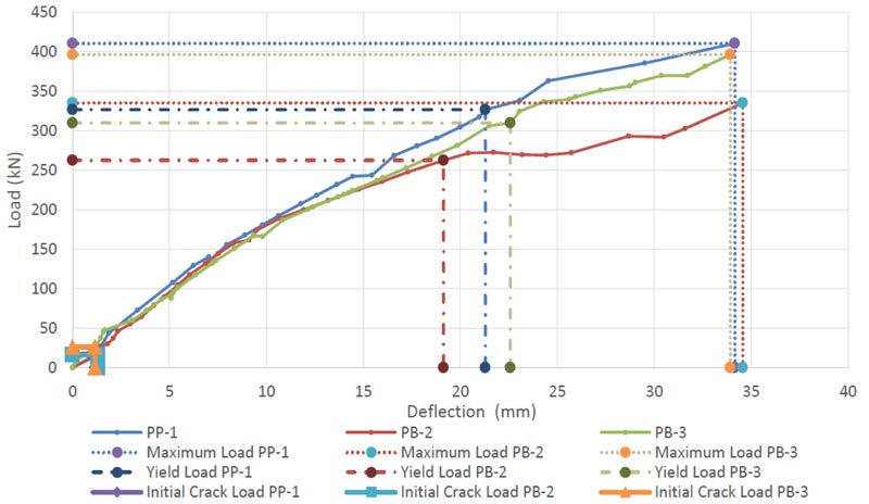
The results of the bending test are shown in Fig. (7). The test is carried out to determine the flexural strength of each specimen consisting of one solid reinforced concrete plate (PP-1) with a thickness of 140 mm as a comparison of 140 mm thick hollow reinforced concrete slabs (PB-2) and 159 mm thick (PB-3).
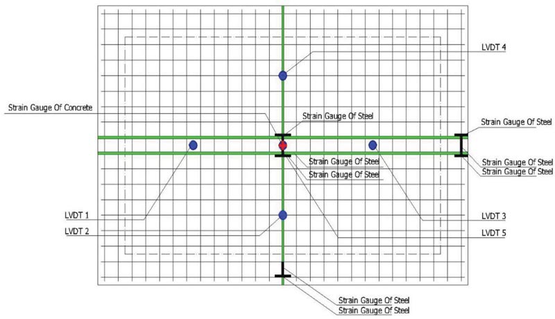
In the early stages of loading, all plates are not cracked. The plates withstand the compressive and tensile forces. When the applied load reaches the flexural stress (fr) on the specimen, the concrete begins to crack. It causes a decrease in the bending stiffness of the plates. After the concrete's tensile area is damaged, the ability to withstand the tensile force is negligible. The plate's initial cracking causes reduced plate stiffness but do not cause a significant reduction in the load-deflection slope. Table 6 shows the relationship between load and plate deflection in the middle of the span on plates PP-1, PB-2, and PB-2, with the limit boundary conditions before the beam flexural collapse occurs according to the initial yield and ultimate cracking stages.
| Specment | Load (kg) |
Load (P) (kN) |
Fc’ = P/A (Mpa) |
Fcr (Mpa) |
Fc; (Mpa) |
|---|---|---|---|---|---|
| 1 2 3 4 |
12,41 12,32 12,32 12,44 |
582,61 567,97 520 535 |
32,98 32,16 29,41 30,26 |
31,19 | 28,51 |
| Number | Dimentions | Load | S1 | S2 | ε2 | Ec |
|---|---|---|---|---|---|---|
| Specimen | (mm) | (kN) | (Mpa) | (Mpa) | (µ) | (Mpa) |
| 1. | Ø 100x200 | 32,09 | 0,513 | 12,84 | 586,48 | 22970,56 |
| 2. | Ø 100x200 | 32,76 | 1,408 | 13,10 | 624,28 | 20367,86 |
| 3. | Ø 100x200 | 23,80 | 1,339 | 9,52 | 447,89 | 20559,06 |
| Average | 21299,16 | |||||
| Empiris (Ec=4700√fc’) | 25104,34 | |||||
| Plate | Pcr | Py | Pu | Deflection (mm) | ||
|---|---|---|---|---|---|---|
| (kN) | (kN) | (kN) | Initial Crack | Yield | Maximum | |
| PP-1 | 17,4 | 326,483 | 410,642 | 1,22 | 21,3 | 34,18 |
| PB-2 | 16,2 | 262,393 | 335,18 | 1,31 | 19,14 | 34,59 |
| PB-3 | 25,7 | 309,632 | 396,257 | 1,15 | 22,6 | 33,93 |
4.6. Plate Deflection
Deflection on the plate needs to be known and limited. If the deflection is too large, it can reduce serviceability and damage the non-structural parts connected to the plate. In the slab used for the roof,
large deflections can cause rain puddles that will put additional weight on the roof. The comparison of the initial crack deflection between experimental result and theory are shown in Table 7.
The initial crack deflection experimental results show greater results than the results of the analysis using the Navier method, this is because the Navier method is more suitable for thin plate deflection analysis, while the results of the Ugural method analysis are more suitable for deflection analysis on thick plates, which produce slightly more values than the experimental results due to the imperfect compaction of the specimens.
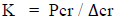
4.7. Stiffness
Stiffness is defined as the force required to produce a deflection of one unit. The stiffness of the scan method can calculate the plate stiffness from the experimental results by observing the deflection in the middle of the plate span and the load when the plate reaches its elastic limit or when the initial crack (Table 8).
| Plate | Experiment (mm) |
Navier Theory (mm) |
Ugural Theory (mm) |
|---|---|---|---|
| PP-1 | 1,22 | 0,027 | 1,402 |
| PB-2 | 1,31 | 0,025 | 1,400 |
| PB-3 | 1,15 | 0,023 | 1,204 |
Table 8.
| Plate | Experiment | Deflection Analysis Base On | ||||
|---|---|---|---|---|---|---|
| Load (kN) |
Defelection (mm) |
K (kN/mm) |
Load (kN) |
Ugural (mm) |
K (kN/mm) |
|
| PP-1 | 17,4 | 1,22 | 14,262 | 22,88 | 1,402 | 16,321 |
| PB-2 | 16,2 | 1,31 | 12,366 | 20,70 | 1,400 | 14,787 |
| PB-3 | 25,7 | 1,15 | 22,348 | 28,82 | 1,204 | 24,194 |
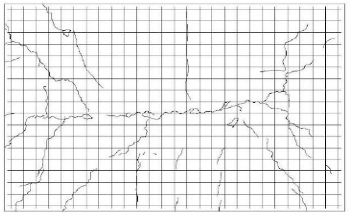
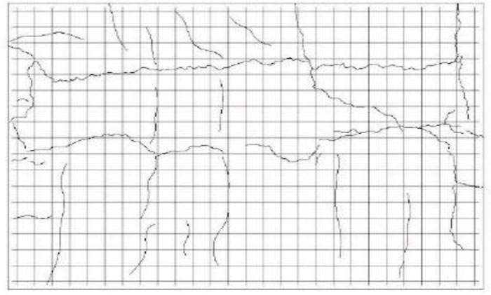
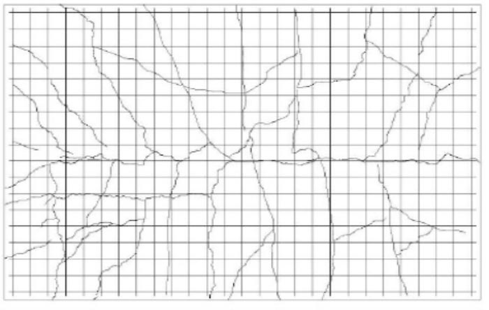
4.8. Crack Pattern
The crack pattern on the PP-1 (Fig.8) is transverse cracks between the plate supports' sides. PP-1 crack pattern is a flexible crack pattern. The crack pattern on the PB-2 (Fig. 9) and the PB-3 (Fig. 10) begins with a transverse crack pattern between the plate support sides, followed by the appearance of a crack that does not cross but forms a crack area. The PB-2 hollow plate and PB-3 hollow plate's crack pattern began with a bending crack pattern, followed by a shear crack pattern.
| Plate | Maximum Load (kN) |
Maximum Deflection (mm) |
Yield Deflection (mm) |
Ductility |
|---|---|---|---|---|
| PP-1 | 410,642 | 34,18 | 21,3 | 1,605 |
| PB-2 | 335,180 | 34,59 | 19,14 | 1,807 |
| PB-3 | 396,257 | 33,93 | 22,6 | 1,501 |
| Plate | Experiment | Shear Analysis | Percentage |
|---|---|---|---|
| (kN) | (kN) | (%) | |
| PP-1 | 339,232 | 965,908 | 35,12 |
| PB-2 | 105,600 | 231,818 | 45,553 |
| PB-3 | 142,200 | 279,503 | 50,876 |
4.9. Ductility
Ductility is the ability of a building structure to experience large post-elastic deviations repeatedly. It causes the first melt to occur while maintaining sufficient strength and stiffness. The plate ductility can be seen from the ratio of deflection at the maximum load to the steel deflection when the reinforcement begins to yield. The comparison can be seen in Table 9.
4.10. Shear Force on Plates
Shear forces can cause damage to the plates. Shear forces can occur due to concentrated loads or area loads. The plate's focused load or area load can cause shear stresses on a surface around the load. The comparison of experimental and analysis results is shown in Table 10.
CONCLUSION
PP-1 plate is used as a control, the initial crack load capacity of PB-2 is 93.103%, and PB-3 is 147.701%. The yield load on PB-2 is 80.379%, and PB-3 is 94.850%, while the maximum load on PB-2 is 81.623% and PB-3 plate is 96.497%. The stiffness in PB-2 is 86.706% and in PB-3 is 146.696%, while the ductility in PB-2 is 101.054% and in PB-3 is 93.427%.
The crack pattern in PP-1 is bending, while the crack pattern in PB-2 and PB-3 is a combination of bending and shear cracks. The placement of cavities on the PB-2 and PB-3 plates makes the
hollow plates susceptible to shear cracks. It happens because the steel's bonding to the concrete
during loading will produce immense stress on the concrete around the reinforcement, which makes the concrete susceptible to shear cracks.
The use of a modified reinforced concrete plate with a PVC pipe modification using the on-site cast method can technically be suggested for use, but it is necessary to pay attention to the concrete compaction process so that the concrete does not porous.
CONSENT FOR PUBLICATION
Not applicable.
FUNDING
None.
CONFLICT OF INTEREST
The authors declare no conflict of interest, financial or otherwise.
ACKNOWLEDGEMENTS
The authors are grateful to Mr. Herman Parung as a Promotor, Mrs. Rita Irmawaty as a Co-Promotor, and Mr. A. Arwin Amiruddin as a Co-Promotor.

