All published articles of this journal are available on ScienceDirect.

Seismic Retrofit of an Existing Reinforced Concrete Building with Buckling-restrained Braces
Authors Info & Affiliations
Abstract
Background:
The seismic retrofitting of frame structures using hysteretic dampers is a very effective strategy to mitigate earthquake-induced risks. However, its application in current practice is rather limited since simple and efficient design methods are still lacking, and the more accurate time-history analysis is time-consuming and computationally demanding.
Aims:
This paper develops and applies a seismic retrofit design method to a complex real case study: An eight-story reinforced concrete residential building equipped with buckling-restrained braces.
Methods:
The design method permits the peak seismic response to be predicted, as well as the dampers to be added in the structure to obtain a uniform distribution of the ductility demand. For that purpose, a pushover analysis with the first mode load pattern is carried out. The corresponding story pushover curves are first idealized using a degrading trilinear model and then used to define the SDOF (Single Degree-of-Freedom) system equivalent to the RC frame. The SDOF system, equivalent to the damped braces, is designed to meet performance criteria based on a target drift angle. An optimal damper distribution rule is used to distribute the damped braces along the elevation to maximize the use of all dampers and obtain a uniform distribution of the ductility demand.
Results:
The effectiveness of the seismic retrofit is finally demonstrated by non-linear time-history analysis using a set of earthquake ground motions with various hazard levels.
Conclusion:
The results proved the design procedure is feasible and effective since it achieves the performance objectives of damage control in structural members and uniform ductility demand in dampers.
1. INTRODUCTION
Many existing buildings in high seismicity regions were designed and constructed without any design provision for earthquake resistance. In these buildings, seismic energy is dissipated by the plastic deformations of the structural elements, which cause performance deterioration and damage. Among possible retrofit strategies, the approach involving both stiff- ness and strength increments has been the most commonly used one over the past decades. The main drawback of this approach is that it increases not only the strength but also the lateral stiffness of the building, thus resulting in higher seismic actions. As an alternative, the concept of passive control strategies based on energy dissipation devices has been significantly developed in recent years [1, 2]. Various types of energy dissipation devices are currently used for the seismic retrofit of reinforced concreted (RC) buildings. Among them, various types of metallic yielding dampers have been developed that use both the plastic deformation capacity and the ductility of hysteretic materials (such as mild steel, aluminum, or shape memory alloys) to dissipate seismic energy [3-10]. These dampers are classified based on the yielding mechanism (i.e., axial dampers, yielding ring dampers, extrusion devices, torsional bar dampers, and shear panel dampers) and used with various configurations (i.e., brace type, wall panel type, stud panel type, and shear link panel type). Nowadays, the elasto-plastic (EP) axial steel dampers are extensively used in diagonal braces for the seismic energy dissipation (i.e., buckling restrained braces) since they significantly decrease both member forces and inter-story drifts under earthquake ground motion. However, their practical design is more complex than other retrofit strategies since they significantly modify both stiffness and damping characteristics of the structure. The increase in lateral stiffness shortens the natural periods of vibration, and this usually increases the acceleration demand. The increase in damping increases the energy dissipation capacity of the structure. Additionally, when the damper yields, often the whole structure loses the lateral stiffness of one story, with the consequent failure due to the development of a soft story mechanism. The design procedure should account for the hysteretic behavior of both the dampers and the RC members and include their interaction under earthquake ground motion. Hence the lack of efficient design methods in the literature, as well as of standardized design procedures in the seismic codes. The application of conventional methods (such as the traditional force-based “R-Factor method” as prescribed in SEI/ASCE 7-05 [11] or the “q-factor method” as suggested in Eurocode 8 [12]) to RC damped braced buildings becomes prohibitively difficult. In fact, due to the lack of stable relationships among damping, response reduction factors, and earthquake ground motion, the behavior factor is difficult to obtain accurately.
On the other side, the application in the current practice of more sophisticated methods, such as the non-linear time-history analysis, is relatively small because it involves many additional data (i.e., accurate hysteretic models and spectrum compatible earthquake records) and requires advanced modeling and computationally intensive analyses. Hence, several methods directed at improving and simplifying the design phase were available in the literature. For example, Foraboschi [13] proposed a simple formula that blends plastic analysis and non-linear analysis to investigate the ultimate behavior of RC structures and developed a predictive formulation for the ultimate combination of axial force and bending moment for steel members [14]. As an alternative to non-linear dynamic analysis, many seismic design procedures have been proposed in the literature [15-22] and implemented in current design codes [23-25]. The state-of-the-art review shows that many of these design methods combine the Displacement-Based Design (DBD) and the proportional stiffness criterion. In this approach, the distribution of the lateral loads on the damped braces is considered proportional to the first mode shape. This hypothesis is assumed to be true in the case of regular structures where the mode shapes remain practically unchanged after retrofitting. However, it fails in many existing RC buildings since they are often irregular in-plan or elevation and may exhibit a poor seismic behavior (e.g., lateral-torsional coupling effects, soft-story mechanisms, and non-ductile columns). Other studies [26-30] proposed damper optimization methods, aiming to obtain uniform ductility demand distributions. However, these methods are generally developed based on simplified shear beam models, while applications to complex multi-story buildings are still lacking. Thus, it is desirable for the development of simple and more practical design procedures and their application to real case studies and, particularly, to schools, hospitals, and other public buildings, considering their importance due to the consequences associated with their failure [31-33]. This paper presents an interesting application of a seismic retrofit design method to an existing reinforced concrete building using Buckling-Restrained Braces (BRBs). The design procedure aims to predict the peak seismic response and arrange dampers to attain a uniform distribution of the ductility demand. For this purpose, a comprehensive design method is developed and applied to address the main issues of the seismic design of damped braces, i.e., complex hysteretic behavior of RC structural members, frame-damped braces interaction, and effect of non-uniform displacement demands and partial collapse mechanisms. Its effectiveness is finally investigated through non-linear response history analyses considering suites of earthquake ground motion records representing different seismic hazard levels.
2. REVIEW OF RETROFIT DESIGN METHODS FOR RC BUILDINGS USING HYSTERETIC DAMPERS
The seismic design standards of several countries apply the energy dissipation concept, and some current design codes [24-26] have developed design principles for the damped structures, including analytical models for the dampers and methods of analysis for the seismic response. In general, the coefficient method based on FEMA 273 [34] and the capacity-spectrum method based on ATC-40 [35] have given rise to two different approaches, one founded on the Direct Displacement-Based Design method (DDBD) and the other based on the Capacity-Spectrum Method (CSM). The design method proposed by the Japan Society of Seismic Isolation [36] applies the so-called elastic response reduction curve. This approach neglects the inelastic behavior of the main structure, thus overestimating the reduction in acceleration. To overcome this limitation, Shen et al. [37] proposed a simple design method based on the Elastic-Plastic Response Reduction Curve (EPRRC). Lee and Kim [38] developed a design procedure based on the capacity spectrum method for the seismic retrofit of an existing reinforced concrete building with steel slit dampers. Lin et al. [18] presented a seismic displacement-based design method and provided the effective viscous damping ratio for various passive energy dissipation devices. Kim et al. [39] proposed a direct displacement design procedure for steel frames with buckling-restrained braces. Teran-Gilmorea et al. [40] introduced a displacement-based methodology for the preliminary design of buckling-restrained braces, neglecting both the higher modes and the torsional effects. Since damage is related to both the maximum displacement and the energy dissipated during the earthquake, various energy-based design methods are available in the literature. Kim et al. [41] proposed a simplified design procedure based on the energy balance concept and equal energy dissipation. Choi et al. [42] presented an energy-based seismic design procedure for framed structures with buckling-restrained braces using hysteretic energy spectra and accumulated ductility spectra. Habibi et al. [43] developed a step-wise multi-mode energy-based design method for seismic retrofitting of frame structures with energy dissipative devices. Recently, optimal design methods aim to define the locations and sizes of the devices to obtain the best performance at a lower cost. Miguel et al. [44] proposed a robust design optimization based on two objective functions and a genetic algorithm that is applied to solve the resulting multi-objective optimization problem. As an alternative to such genetic algorithms, Martínez et al. [45] proposed a stochastic equivalent linearization to optimally define the energy dissipation capacity of added non-linear hysteretic dampers. Terazawa et al. [46] presented a damper design routine for highly indeterminate 3D structures utilizing computational optimization and response spectrum analysis. However, all these methods have important limitations since they are time-consuming and computationally demanding, especially when applied to complex buildings. Furthermore, results may vary significantly with different earthquake ground motions. Finally, many of these design methods base on steel structures, where the beam-column brace connections are pinned, and the damped braces resist all the lateral seismic forces. Many other studies neglect the real nature of the building after retrofit that is a dual system (bare frame plus dissipating braces) with a not negligible frame-damped brace interaction. Mazza et al. [21] proposed a design procedure that arranges the dampers accor- ding to the fundamental mode based on the Displacement-Based Design (DBD) and the proportional stiffness criterion. The SDOF system, equivalent to the existing building, and the SDOF system, equivalent to the damped braces, were considered separately, thus neglecting the frame-damped brace interaction. Moreover, the RC frame contribution to the pushover capacity of the building depends on the non-linear response of the structure that may be significantly modified by the addition of the damped braces. To overcome these limi- tations, Ferraioli and Lavino [22] developed a displacement-based design method based on the adaptive pushover analysis that explicitly accounts for the frame-damped brace interaction. Other studies [26-30, 36] proposed a closed-form formula for the damper-frame stiffness ratio and a rule to distribute the damper stiffness over the height of the structure. However, both methodological and practical problems limit their application in the current practice. This approach bases on two-dimensional planar shear-bar models. Thus, it is fully reliable only when applied to symmetric-in-plan buildings with a first-mode dominant response. On the contrary, many existing RC buildings are asymmetric in-plan or irregular in elevation. Thus, their seismic response is significantly affected by the lateral-torsional coupling and the higher modes contribution producing non-uniform displacement demands and partial collapse mechanisms. Moreover, this approach may give inconsistent results for both “upper-deformed type” frames and “lower-deformed type” frames. When applied to “upper-deformed type” frames (i.e., frames where the drift at upper stories increases), this approach provides that no damped brace is necessary for the first story. This design solution would produce a brittle mechanism due to the shear failure of the columns. When applied to “lower-deformed type” frames (i.e., frames where the drift at lower stories increases), this approach could provide a negative stiffness for the damped braces at the upper stories. This negative value means that the story stiffness of the RC frame at the upper stories is too high, thus preventing the yielding of the damped braces. Therefore, more developments and applications to complex buildings are necessary to address the main issues involved in the implementation of efficient retrofit design procedures.
3. MATERIALS AND METHODS
3.1. Retrofit Design Method
3.1.1. Pushover Analysis and Trilinear Idealization of the Story Pushover Curves
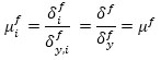
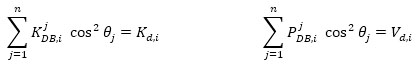
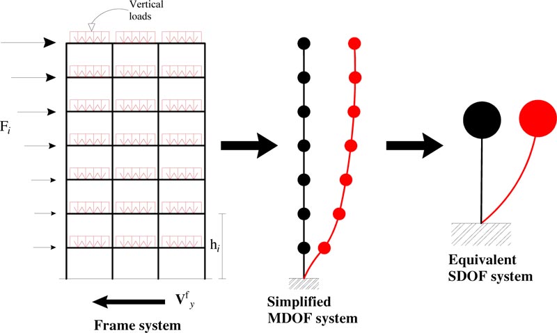
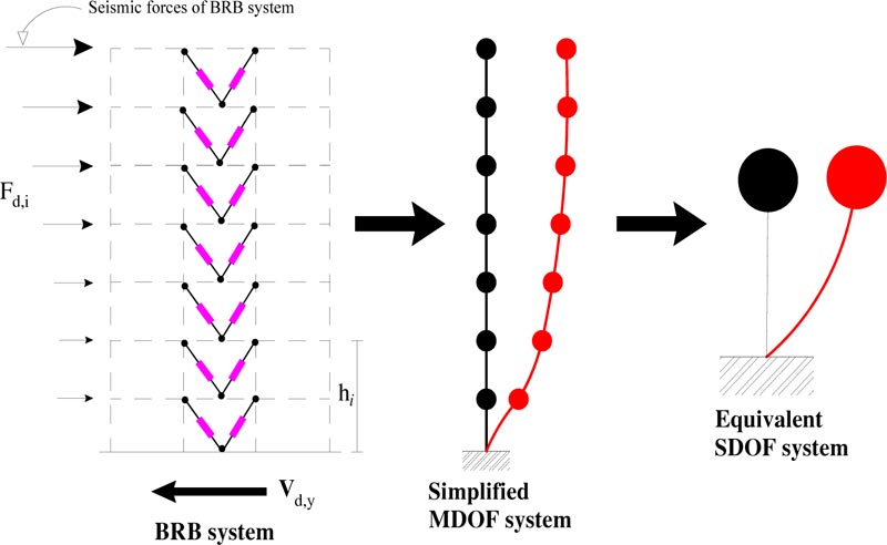
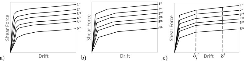
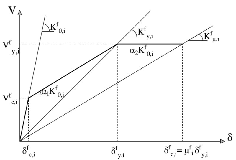
The design procedure bases on decomposing the structural system into two subsystems: the frame system and the damped brace system (Fig. 1). Each subsystem is idealized using first a simplified MDOF model, and then an equivalent SDOF system (Figs. 2-3). The SDOF system, equivalent to the RC frame, is defined based on the pushover analysis using the first mode distribution of lateral forces. The corresponding story pushover curves are plotted in Fig. (4a). Each story pushover curve is then idealized using a degrading trilinear behavior following the Takeda model [47]. The parameters of the trilinear idealization of the pushover curve for the i-th story are shown in Fig. (5), where:
− Kf0,i, α1Kf0,i and α2Kf0,i are the elastic, post-crack, and post-yield stiffness;
− Vfy,i, δfy,i and Kfy,i are the shear force, the inter-story displacement, and the secant stiffness at yielding;
− Vfc,i and δfc,i are the shear force and the inter-story displacement corresponding to cracking of concrete;
− δfi = μfi δfy,i and Kfμ,i are the maximum inter-story displacement and the corresponding secant stiffness.
To calculate these parameters, in this paper the following hypotheses are made:
1) the elastic stiffness Kf0,i is calculated as the tangent stiffness of the pushover curve;
2) the post-yield stiffness is assumed to be zero (i.e., α2 = 0);
Under these hypotheses, the yielding displacement δfy,i is the only unknown parameter of the problem. Sutcu et al. [5] used the condition μfc,i = δfc,i / δfy,i = 1/10 to calculate δfy,i = 10δfc,i and, then, α1 = 0.22 and αy = Qfy,i / δfy,i = 0.3. In this paper, δfy,i comes from the equal energy criterion between the original pushover curve and its trilinear idealization, which gives the trilinear curves shown in Fig. (4b).
3.1.2. Equivalent SDOF System of the RC Frame
The SDOF system, equivalent to the RC frame, is defined in the hypothesis that all the stories have the same yield displacement, calculated using the mean value, as follows:
 |
(1) |
where N is the number of stories of the building. Likewise, the same maximum inter-story displacement and corresponding ductility ratio are considered for all the stories, as follows:
 |
(2) |
 |
(3) |
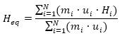
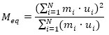
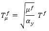
Under the aforementioned hypothesis, the pushover curves are idealized using a simplified trilinear model (Fig. 4c). The equivalent height (Heq), mass (Meq), and period (Tμf) of the SDOF system, equivalent to the RC frame, are defined as follows:
 |
(4) |
 |
(5) |
 |
(6) |
where mi is the i-th story mass, ui is the first mode displacement of the building without dampers at height Hi, while T f is the fundamental vibration period of the bare frame building. The drift angle of the SDOF frame model is given by:
 |
(7) |
where u 0 is the displacement of the building MDOF model at the equivalent height Heq. The displacement demand and the corresponding drift angle demand may be calculated from the fundamental vibration period of the equivalent SDOF system, as follows:
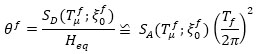 |
(8) |
where 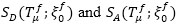 are the values of spectral displacement and acceleration of the SDOF system, equivalent to the RC frame, as a function of the corresponding fundamental vibration period Tfμ and the equivalent viscous damping
  .
.
3.1.3. Design of the Damped Braces
The SDOF system, equivalent to the damped braces, is designed to meet the performance criteria based on the pre-fixed value of the target drift angle θmax. For this purpose, the damper to RC frame stiffness ratio rd = Kd / Kf is calculated using the following closed-form expression proposed by Kasai et al. [28].
 |
(9) |
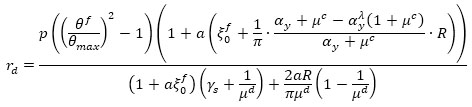
where μf and μc are the maximum and cracking ductility ratio of the bare frame, μd is the damper ductility ratio, a=25, R=0.6, λ = 0.5, and γs is the steel frame-damper stiffness ratio (γs = 0 if no elastic steel frame connects the dampers to the structure). The lateral stiffness of the SDOF system, equivalent to the damped braces, is then distributed along with the height according to the following optimal dampers distribution rule [5]:
 |
(10) |
where Kd,i and Vi are, respectively, the damper lateral stiffness and the design shear force at the i-th story. This stiffness distribution bases on the following constraints:
1) The equivalent viscous damping of the MDOF system is the same as the SDOF system;
2) The distributions of the drift angle and the ductility demand of the damped braced frame system are uniform along with the height, although those of the RC frame is non-uniform;
3) The distribution of the yield drift angle of the dampers is uniform along with the height.
The overall design strength of the damped braces at the i-th story is calculated from the lateral stiffness Kd,i as follows:
 |
(11) |
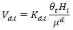
The axial stiffness K jDB,i and strength P jDB,i of the j-th damped brace at the i-th floor should satisfy the following equations:
 |
(12) |
where θj is the inclination angle of the j-th brace, and n is the number of the damped braces. The overall story stiffness of the damped braces given by Eq. (12) is then distributed in-plan to increase the torsional stiffness of the building and minimize the impact on the architectural functionality. The axial stiffness K jDB,i and the axial strength P jDB,i are then used to size the brace and the damper. The axial stiffness of the damper (K jD,i) and the axial stiffness of the brace (K jB,i) should satisfy the following equation:
 |
(13) |
Moreover, the axial strength P jDB,i of the damped brace (i.e., the axial strength of the damper) should be lower than the buckling strength of the brace according to the capacity design rule.
4. RESULTS AND DISCUSSION
4.1. The Case Study RC School Residential Building
4.1.1. Description, in situ Measurements and Laboratory Tests
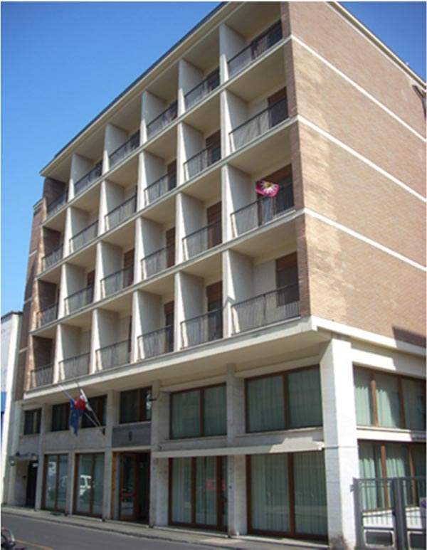
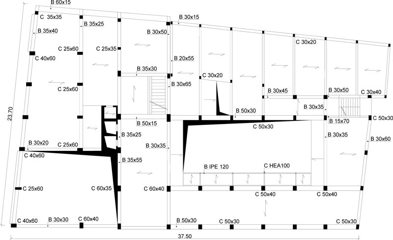
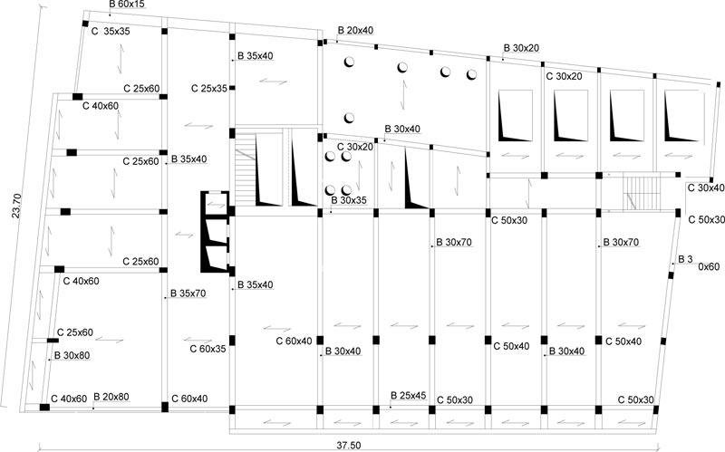
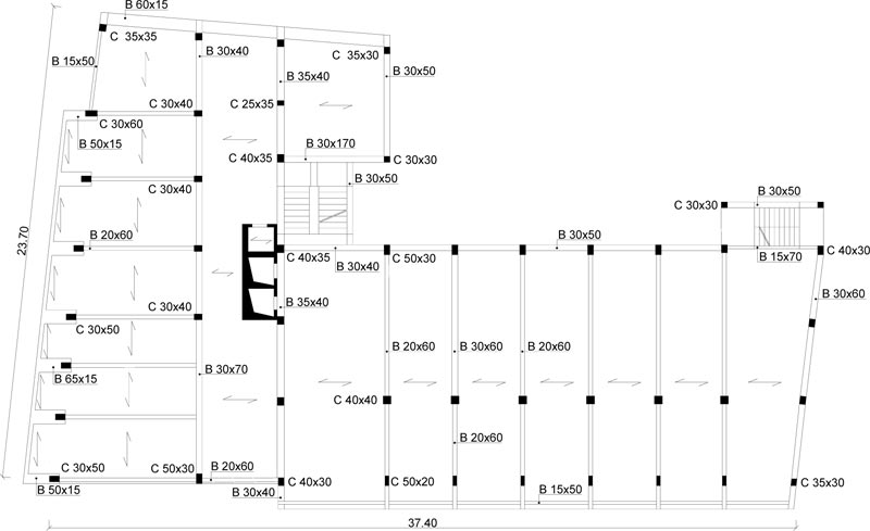
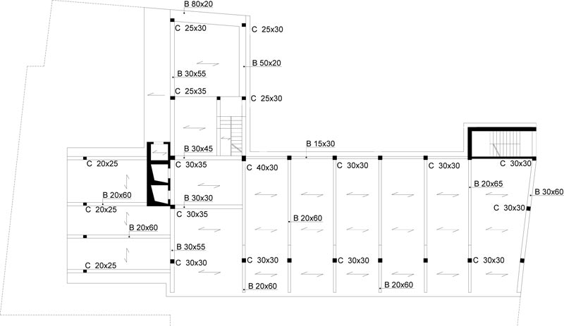
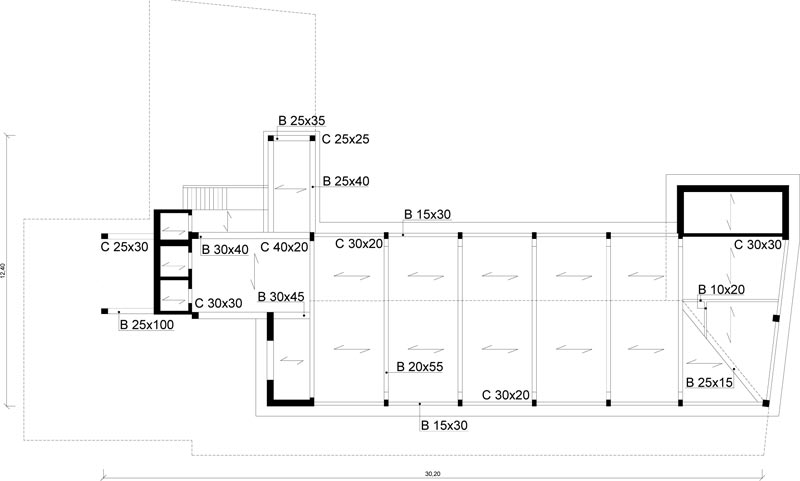
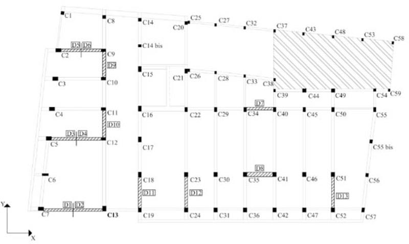
The case study deals with an eight-story school residential building in Pisa, Tuscany (Italy) Fig. (6). The structure, built at the end of the 1950s, consists of reinforced concrete frames running especially in one direction Figs. (7, 8). The building has a rectangular-shaped floor plan for the first two levels with dimensions of about 23.7x37.5m (Figs. 7, 8), while the other floors have an L-shaped plan (Figs. 9-11). The floors have a mixed structure made up of reinforced concrete and tiles. The following investigations were carried out: 1) geometrical measurements; 2) sub-soil investigations; 3) materials testing on samples taken out from the structure. The sub-soil class, according to Eurocode 8 [12] and Italian Seismic Code [48], was ground type D. The topographic coefficient ST = 1.0 for slope category T1 was considered in the analysis. A nominal life VN=50 years and a class of use III (Cu=1.5) were selected, resulting in a reference life VR=75 years. The parameters of the elastic design response spectra used for seismic assessment are plotted in Table 1. The geometry and structural details were known from original outline construction drawings integrated by a direct visual survey. The mechanical properties of the construction materials were taken from limited in-situ testing. Results gave mean values of strength fcm=27.5 MPa for concrete and fym=378 MPa for steel rebars. The mean strength values should be divided by the Confidence Factor CF corresponding to the knowledge level. In the case study, due to the extensive measuring and testing, the full knowledge level KL3 [12, 49] it attained, which implies a Confidence Factor CF = 1.
4.1.2. Seismic Assessment
The seismic performance evaluation was developed according to the Italian Code [48, 49] and Annex B of EN 1998-3 [50].
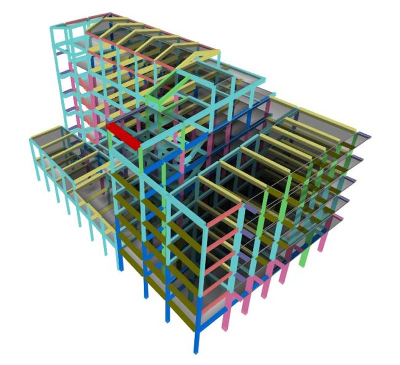
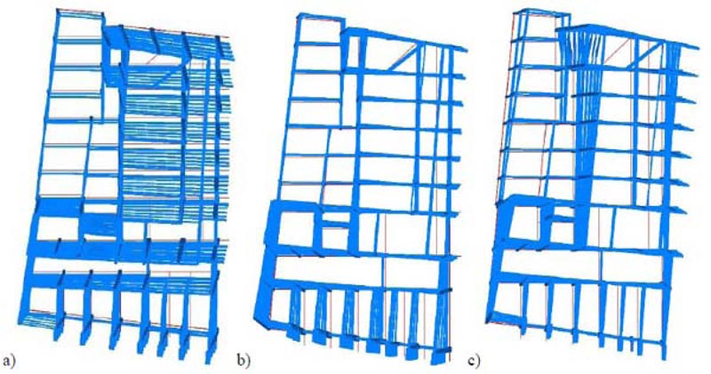
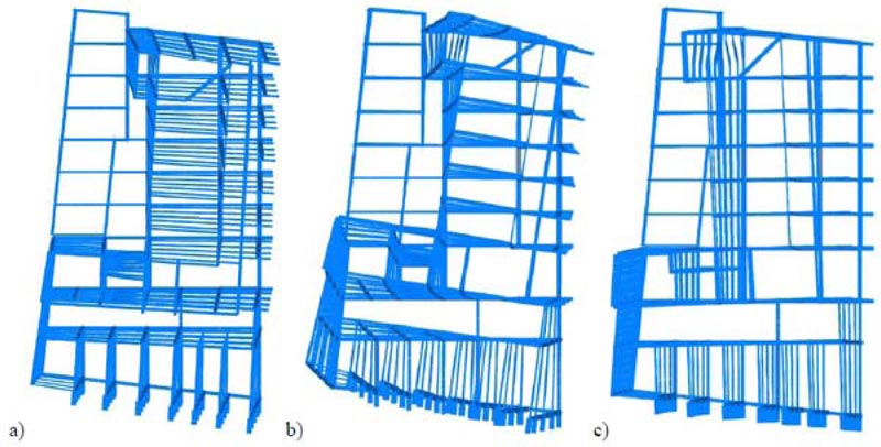
The Limit States of Immediate Occupancy (IO), Damage Limitation (DL), and Life Safety (LS) were considered in the analysis. The RC framed structure was modeled in SAP2000 [51] finite element computer program (Fig. 12). Fig. (13) shows the first three mode shapes of the existing structure and the corresponding dynamic properties (i.e., period Ti, and modal mass ratios αi,x and αi,y in X- and Y-directions, respectively). A fiber plastic hinge model was implemented for the non-linear analysis.
The concrete was modeled with the stress-strain relationship originally proposed by Mander et al. [52]. The steel was modeled with an elastic-plastic-hardening relation- ship. Two vertical distributions of the lateral loads were applied: a “modal” pattern and a “uniform” pattern distribution. The “modal” pattern (Group 1) is proportional to the lateral forces consistent with the lateral force distribution in the direction under consideration determined in the elastic analysis. The “uniform” pattern (Group 2) uses lateral forces that are proportional to mass. According to Eurocode 8 [12] and Italian Code [48] provisions, the analysis considers an accidental eccentricity of 5% of the building dimension perpendicular to the direction of excitation. The seismic performance evaluation applies the procedure reported in both the Annex B of EN 1998-3 [50] and the current Italian Code [48, 49].
The Limit State (LS) of Damage Limitation (DL) occurs when the chord rotation reaches the limit value at yielding, evaluated by the formula (A.10b) of EN 1998-3 [50]. Addi- tionally, the drift acceptance criteria identify the LS of Damage Limitation (DL) and Immediate Occupancy (IO) (i.e., drift ratio of 0.005 for LS of DL and 2/3x0.005 for LS of IO).
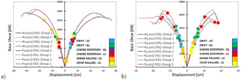
The Limit State (LS) of Life Safety (LS) occurs when the seismic demand reaches the structural capacity. The capacity of ductile and brittle members was estimated in terms of chord rotation and shear strength, respectively. The deformation capacity of beams and columns was defined in terms of the chord rotation according to Appendix A of EN 1998-3 [50]. The chord rotation relative to the LS of LS was assumed as 3/4 of the ultimate value given by the formula A.1 of EN 1998-3 [50]. The pushover curves of the existing building and the performance points corresponding to the different limit states are plotted in Fig. (14). The results in X-direction show that the chord rotation limit state of Life Safety (LS) is reached on the linear branch of the pushover curve. The reason for this behavior was the low ductility capacity of the first-story columns of the staircase structure on the right side of the plan (Fig. 7). The poor ductile performance of these columns comes from their non-seismic reinforcement detailing and high axial force under seismic loading due to the staircase knee beams. Table 2 shows the synthesis of seismic safety verification. The results refer to the following limit states: a) Shear failure of RC members, b) Beam-column joint failure, c) Chord rotation for the LS of Damage Limitation (DL), d) Chord rotation for the LS of Life Safety (LS), e) Immediate Occupancy (IO), f) Damage Limitation (DL), g) 15% Strength Reduction in beams. The peak ground acceleration (PGA), return period (T), and safety index (ζΕ) for the different limit states are plotted. Many deficiencies were found: 1) poor shear capacity of brittle components (ζΕ =0.056 for the shear failure of RC members; ζΕ =0.112 for beam-column joint failure); 2) Inadequate chord rotation capacity for the LS of LS (ζΕ =0.093); 3) Inadequate lateral stiffness especially in X-direction for both the LS of IO (ζΕ =0.561) and the LS of DL (ζΕ =0.727).
4.1.3. Seismic Retrofit with Buckling Restrained Braces
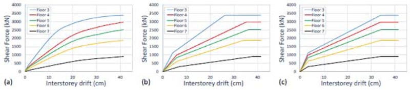
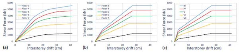
The seismic design of the damped braces was carried out as described in Section 3 above. At first, a pushover analysis was carried out using the first mode distribution of the lateral forces. This approach accurately estimates the seismic response of low-rise and regular buildings where both torsional and higher modes effects are negligible. On the contrary, the existing pre-seismic code buildings are often irregular in plan and/or elevation. Thus, the higher mode effects in plan (torsion) and elevation may strongly influence their seismic response. However, in the case study, the first mode is dominant in both X- and Y- directions. Moreover, the non-linear static analysis does not highlight a local or soft story mechanism. Figs. (15a-16a) show the pushover curves in X- and Y- directions, respectively. In the case study, the design strategy bases on two global retrofit methods: 1) RC shear walls in the first two stories; 2) buckling restrained braces in the subsequent stories. Moreover, the attic floor is not considered in the design procedure. Thus, Figs. (15-16) show the story pushover curves from 3rd to 7th floor. The trilinear idealization of the pushover curves is shown in Figs. (15b-16b). The corresponding parameters are plotted in Tables 3 and 4.
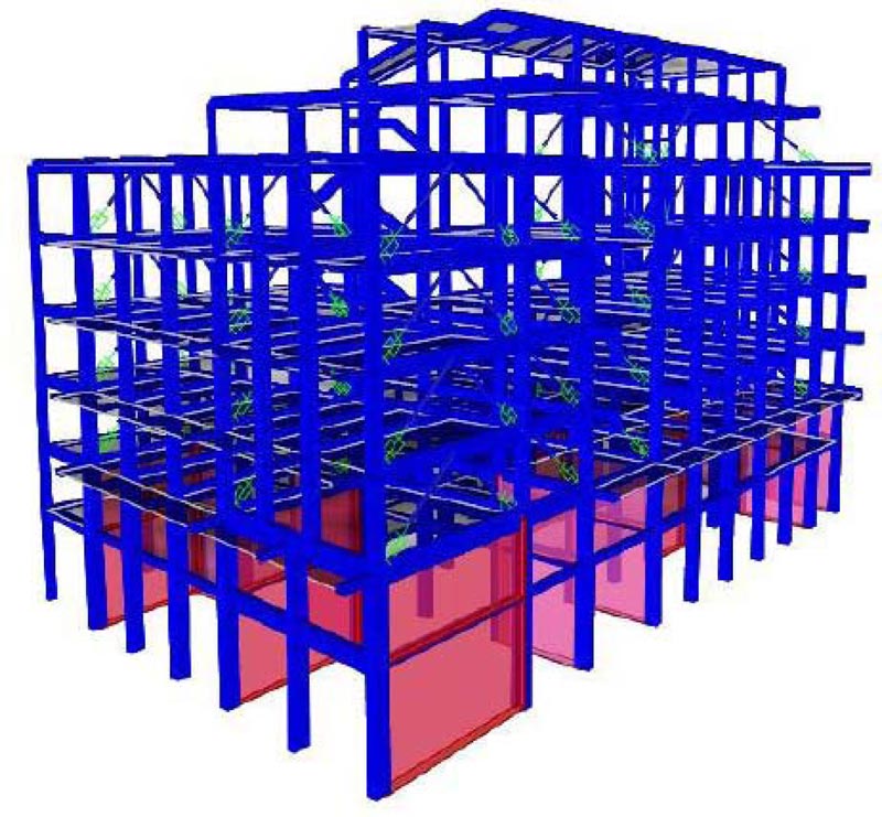
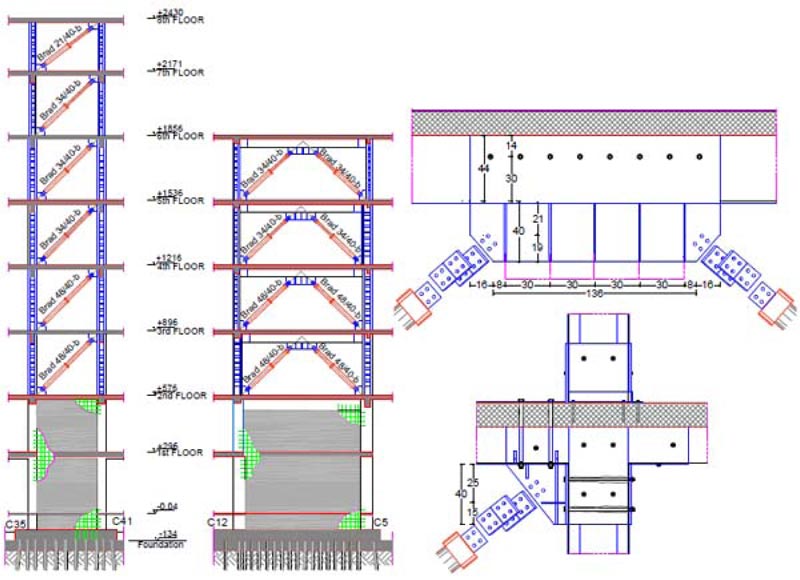
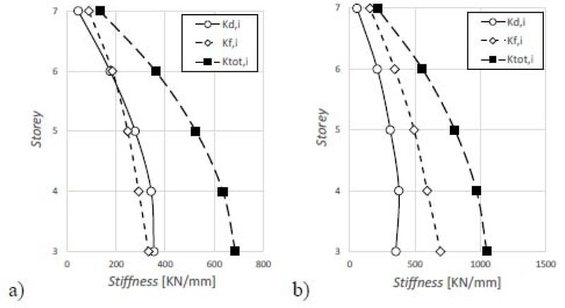
The simplified trilinear curves as defined in Section 3.1.1 are plotted in Figs. (15c-16c). In general, both yield and maximum displacement may considerably change from one story to another, especially for existing pre-seismic code buildings that often exhibit soft-story or torsional failure mechanisms. In this case, the trilinear modeling of the pushover curves becomes prohibitive. However, this situation does not occur in the case study. The SDOF system, equivalent to the RC frame, was defined based on Eqs. (4-6). The equivalent height Heq and mass Meq are shown in Table 5. The SDOF system, equivalent to the damped braces, was designed using Eq. (9) and considering BRBs with a ductility ratio of 10 and hardening stiffness ratio of 2%. The design parameters are shown in Table 6. The period of the SDOF system, equivalent to the RC frame, assumes different values in X- and Y- directions. Thus, according to Eq. (9) also the damper to frame stiffness ratio rd has different values in the two directions (i.e., rd=1.04 in X-direction, and rd=0.57 in Y-direction). The lateral stiffness of the SDOF system, equivalent to the damped braces, is then distributed along with the height according to the optimal distribution rule of Eq. (10) (Fig. 17). The in-plan stiffness distribution of the damped braces is then selected to minimize the impact of bracing on architectural functionality and increase the torsional stiffness of the building (Fig. 18). This gives the axial stiffness KjDB,i of each damped brace (Tables 7 and 8) that is used to size the brace and the damper. The values of their stiffness should satisfy Eq. (13). Moreover, according to the hierarchy design criterion, the axial strength PjDB,i of the damped brace (i.e., the axial strength of the damper) should be lower than the buckling strength of the brace. The dampers and braces used in X- and Y-directions are summarized in Tables 9 and 10, respectively. The 3D model of the RC building after retrofit is shown in Fig. (19). The corresponding mode shapes and dynamic properties are plotted in Fig. (20) and Table 11. Finally, it should be highlighted that the retrofit scheme consists of both global (i.e., RC shear walls for the first two stories, and BRBs otherwise) and local retrofit strategies (Fig. 21), including strengthening of columns next to the steel braces by steel angles and strips, shear strengthening of unconfined joints with Fiber-Reinforced Polymers (FRP), shear and bending reinforcement of some beams with FRP and foundation retrofit with micro piles.
4.2. Seismic Assessment of Retrofitted Structure
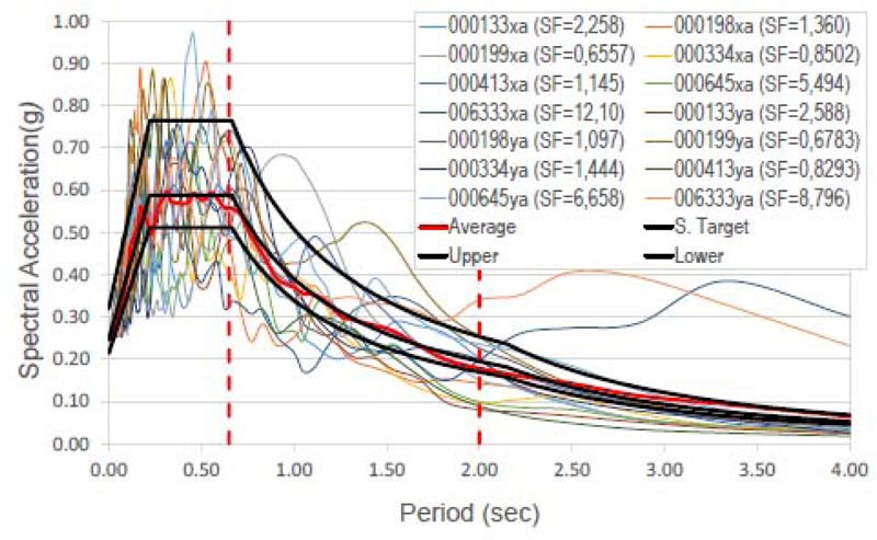
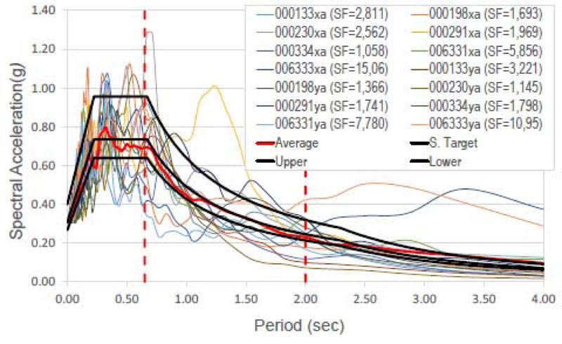
The effectiveness of the seismic retrofit method is finally demonstrated by the non-linear time-history analysis using the well-known Bouc-Wen model [53] for the hysteretic dampers and the non-linear fiber hinge model for the RC members. The building was subjected to bi-directional excitations repre- senting the two horizontal components of the earthquake ground motion. Following the provisions of the Italian Code [48], two suites of seven earthquake ground motions were selected, the first for the Life Safety (LS) Limit State and the second for the Collapse Prevention (CP) Limit State. The design value of the seismic effect is the average of the response quantities from all the analyses. The SIMBAD database (Selected Input Motions for displacement-based Assessment and Design), the European Strong-motion Database (ESD), and the Italian Accelerometric archive (ITACA) [54, 55] have given the selected accelerograms. Spectrum-compatible signals were obtained scaling real records and observing the following rules provided by the Italian Code [48]: 1) the mean of the zero period spectral response acceleration values is not smaller than agS, where S is the soil factor and ag is the design ground acceleration on type A ground; 2) in the range of periods of interest no value of the mean elastic spectrum is less than 90% of the corresponding value of the target elastic spectrum. The parameters of the accelerograms used in the dynamic analysis are plotted in Tables 12 and 13. Their spectrum compatibility and Scaling Factors (SF) are shown in Figs. (22 and 23). The Collapse Prevention (CP) limit state was verified by direct comparison of the calculated displacement ductility demand of the hysteretic dampers to the corresponding displacement ductility capacity. Figs. (24 and 25) show the hysteresis loops of some dampers in X- and Y-direction, respectively, under the seven time-histories considered for the Collapse Prevention Limit State.
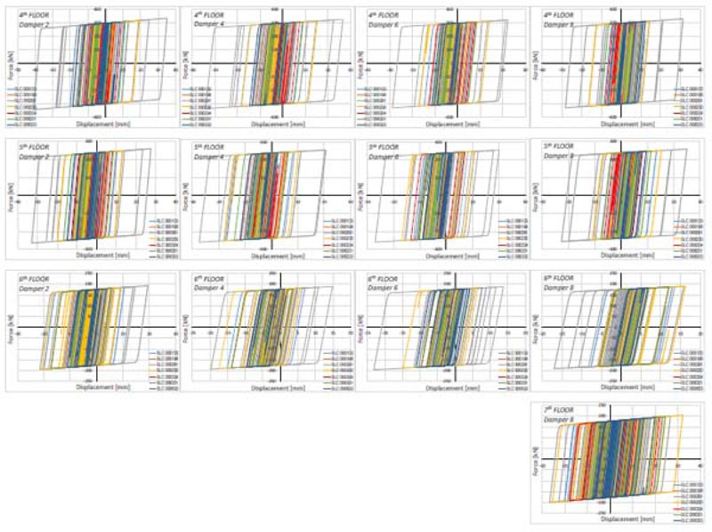
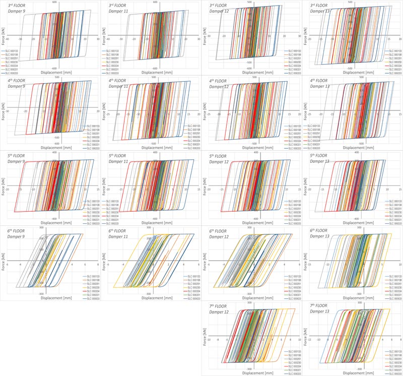
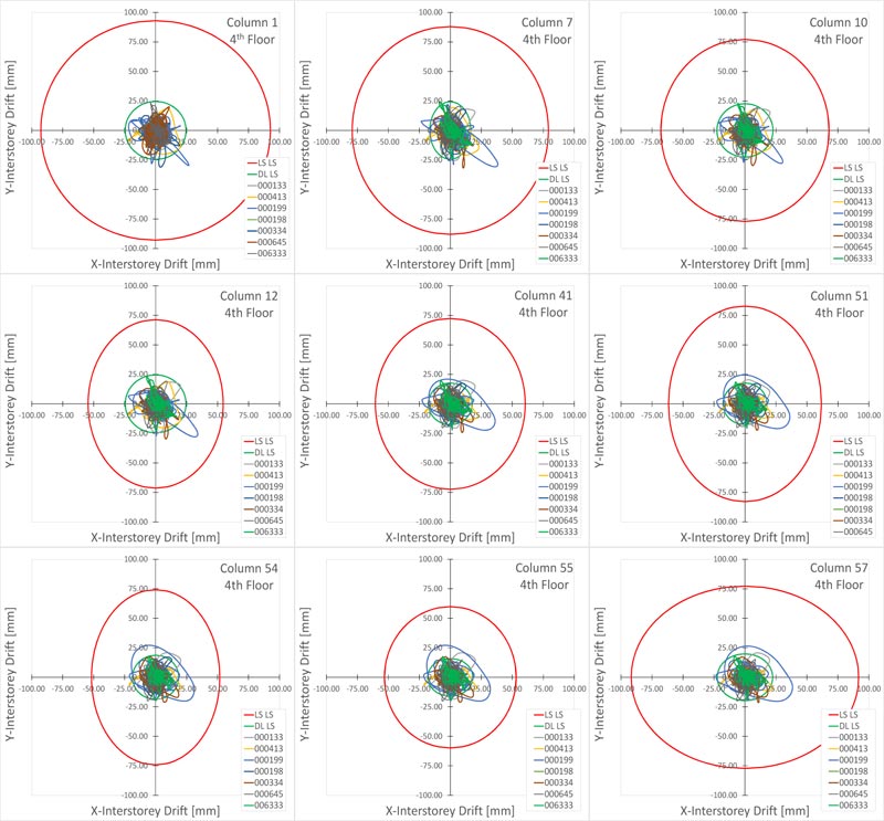
Very large plastic strains were observed in all the dampers, thus evidencing the effectiveness of the design method. The average of the peak displacements from the seven earthquakes was used as the design value of the seismic effect. It should be highlighted that no damper exceeds its capacity of 20 mm, corresponding to its displacement ductility capacity ratio μd=10. According to both Eurocode 8 [12] and Italian Code [48, 49], the Life Safety verification compared the member chord rotation demand in beams and columns to the corres- ponding chord rotation capacity. As far as columns are concerned, this comparison is carried out in terms of inter-story drift. The demand is given by the inter-story drift time-histories for the selected earthquake records. The capacity is represented by the limit domain for the limit states of Life Safety (LS) and Damage Limitation (DL) calculated from the corresponding chord rotation. For the Limit State of Damage Limitation (DL), the chord rotation at yielding (θy) was estimated by the formula (A.10b) and (A.11b) from EN 1998-3 [50]. For the Limit State of Life Safety (LS), the chord rotation is assumed as 3/4 of the ultimate chord rotation θu defined by the formula A.1 from EN 1998-3 [50]. In columns, under seismic ground motion, the nodal rotation is low compared to the drift Δ of the equivalent cantilever. Thus, the chord rotation θ is given by Δ/Ls, where Ls is the shear span length considered placed at the middle of the column. The drift capacity depends on the direction of the bending axle in bi-axial bending. However, a study available in the literature [56] shows that the interaction diagram is circular if the components of chord rotation along the sides of the section in bi-axial bending are normalized to the corresponding chord rotations in uniaxial loading. Fig. (26) shows the comparison between capacity and demand in terms of the maximum inter-story drift of the columns.
| Limit State | IO | DL | LS | CP |
|---|---|---|---|---|
| Probability of exceedance PVR | 0.81 | 0.63 | 0.10 | 0.05 |
| Return Period TR (years) | 45 | 75 | 712 | 1462 |
| Peak ground acceleration PGA/g | 0.046 | 0.056 | 0.137 | 0.173 |
| Amplification factor Fo | 2.553 | 2.567 | 2.391 | 2.385 |
| Transition Period TC (s) | 0.243 | 0.259 | 0.281 | 0.286 |
| Limit State | Comb. | Group | PGA [g] |
T [years] |
ζE |
|---|---|---|---|---|---|
| a) Shear failure of RC members | -Fy, ecc(-5%) | 1 | 0.00786 | 6 | 0.056 |
| b) Beam-column joint failure | -Fx, ecc(+5%) | 1 | 0.0157 | 12 | 0.112 |
| c) Chord Rotation DL | -Fy, ecc(-5%) | 2 | 0.0337 | 26 | 0.797 |
| d) Chord Rotation LS | -Fy+ ecc(+5%) | 1 | 0.0129 | 10 | 0.093 |
| e) Drift IO | -Fy, ecc(-5%) | 1 | 0.0258 | 20 | 0.561 |
| f) Drift DL | -Fy, ecc(-5%) | 2 | 0.0410 | 34 | 0.727 |
| g) 15% Strength Reduction in beams | +Fy, ecc(-5%) | 1 | 0.1730 | 1455 | 1.252 |
| Floor |
δfc,i [mm] |
Qfc,i [kN] |
δfy,i [mm] |
Qfy,i [kN] |
Kf0,i [kN/mm] |
α1Kf0,i [kN/mm] |
δfi [mm] |
μfi |
Kfy,i [kN/mm] |
Kfμ,i [kN/mm] |
|---|---|---|---|---|---|---|---|---|---|---|
| 3 | 3.39 | 1126.56 | 33.92 | 3379.67 | 332.11 | 73.80 | 41.33 | 1.22 | 99.63 | 81.77 |
| 4 | 3.39 | 990.59 | 33.92 | 2971.76 | 292.02 | 64.89 | 41.33 | 1.22 | 87.61 | 71.90 |
| 5 | 3.39 | 839.65 | 33.92 | 2518.96 | 247.53 | 55.01 | 41.33 | 1.22 | 74.26 | 60.94 |
| 6 | 3.39 | 626.72 | 33.92 | 1880.17 | 184.76 | 41.06 | 41.33 | 1.22 | 55.43 | 45.49 |
| 7 | 3.39 | 301.98 | 33.92 | 905.95 | 89.02 | 19.78 | 41.33 | 1.22 | 26.71 | 21.92 |
| Floor |
δfc,i [mm] |
Qfc,i [kN] |
δfy,i [mm] |
Qfy,i [kN] |
Kf0,i [kN/mm] |
α1Kf0,i [kN/mm] |
δfi [mm] |
μfi |
Kfy,i [kN/mm] |
Kfμ,i [kN/mm] |
|---|---|---|---|---|---|---|---|---|---|---|
| 3 | 2.68 | 1863.94 | 26.81 | 5591.83 | 695.13 | 154.47 | 41.33 | 1.54 | 208.54 | 135.29 |
| 4 | 2.68 | 1590.59 | 26.81 | 4771.78 | 539.19 | 131.82 | 41.33 | 1.54 | 177.96 | 115.45 |
| 5 | 2.68 | 1321.49 | 26.81 | 3964.46 | 492.83 | 109.52 | 41.33 | 1.54 | 147.85 | 95.91 |
| 6 | 2.68 | 926.21 | 26.81 | 2778.64 | 345.42 | 76.76 | 41.33 | 1.54 | 103.63 | 67.23 |
| 7 | 2.68 | 418.00 | 26.81 | 1254.00 | 155.89 | 34.64 | 41.33 | 1.54 | 46.77 | 30.34 |
| Floor |
mi [kNs2/m] |
Hi [m] |
mi x Hi2 [kNs2m] |
mi x Hi [kNs2] |
|---|---|---|---|---|
| 3 | 450.75 | 3.1 | 4333.71 | 1397.33 |
| 4 | 443.18 | 6.2 | 17035.66 | 2747.69 |
| 5 | 438.81 | 9.3 | 37952.45 | 4080.91 |
| 6 | 456.62 | 12.4 | 70209.23 | 5662.03 |
| 7 | 230.42 | 15.5 | 55357.91 | 3571.48 |
| - | - | - | 184886.95 | 17459.43 |
| Direction | a | R | λ | γs | p | αy |
Tf [s] |
Tμf [s] |
SD [m] |
θf | θmax | ξ0f | μd | rd |
|---|---|---|---|---|---|---|---|---|---|---|---|---|---|---|
| X | 25 | 0.60 | 0,50 | 0.05 | 0.25 | 0.30 | 1.02 | 2.06 | 0.25 | 0.0237 | 0.0133 | 0.03 | 7.00 | 1.04 |
| Y | 25 | 0.60 | 0,50 | 0.05 | 0.19 | 0.30 | 0.754 | 1.71 | 0.21 | 0.0197 | 0.0130 | 0.03 | 8.00 | 0.57 |
| Floor |
Qi [kN] |
Kfμ,i [kN/mm] |
Kd,i [kN/mm] |
n |
Kd,i/n [kN/mm] |
Dampers 1-2 | Dampers 3-4 | Dampers 5-6 | Damper 7 | Damper 8 | |||||
|---|---|---|---|---|---|---|---|---|---|---|---|---|---|---|---|
|
KDB,i [kN/mm] |
θ [°] |
KDB,i [kN/mm] |
θ [°] |
KDB,i [kN/mm] |
θ [°] |
KDB,i [kN/mm] |
θ [°] |
KDB,i [kN/mm] |
θ [°] |
||||||
| 3 | 14938 | 81.77 | 354.26 | 8 | 44.28 | 58.03 | 40.26 | 61.60 | 44.04 | 68.29 | 49.58 | 59.93 | 42.36 | 59.93 | 42.36 |
| 4 | 13742 | 71.90 | 343.15 | 8 | 42.89 | 56.21 | 40.26 | 59.67 | 44.04 | 66.15 | 49.58 | 58.05 | 42.36 | 58.05 | 42.36 |
| 5 | 11391 | 60.94 | 277.48 | 8 | 34.68 | 45.45 | 40.26 | 48.25 | 44.04 | 53.49 | 49.58 | 46.94 | 42.36 | 46.94 | 42.36 |
| 6 | 7899.98 | 45.49 | 175.71 | 8 | 21.96 | 28.78 | 40.26 | 30.55 | 44.04 | 33.87 | 49.58 | 29.72 | 42.36 | 29.72 | 42.36 |
| 7 | 3055.67 | 21.92 | 45.54 | 2 | 22.97 | 29.84 | 40.26 | 31.68 | 44.04 | 35.12 | 49.58 | 30.82 | 42.36 | 30.82 | 42.36 |
| Floor |
Qi [kN] |
Kfμ,i [kN/mm] |
Kd,i [kN/mm] |
n |
Kd,i/n [kN/mm] |
Damper 9 | Damper 10 | Dampers 11-12 | Damper 13 | ||||
|---|---|---|---|---|---|---|---|---|---|---|---|---|---|
|
KDB,i [kN/mm] |
θ [°] |
KDB,i [kN/mm] |
θ [°] |
KDB,i [kN/mm] |
θ [°] |
KDB,i [kN/mm] |
θ [°] |
||||||
| 3 | 14938 | 135.29 | 354.06 | 5 | 70.81 | 97.46 | 43.40 | 95.44 | 42.10 | 88.85 | 37.16 | 88.85 | 37.16 |
| 4 | 13742 | 115.45 | 377.23 | 5 | 75.45 | 103.84 | 43.40 | 101.68 | 42.10 | 94.67 | 37.16 | 94.67 | 37.16 |
| 5 | 11391 | 95.91 | 311.46 | 5 | 62.29 | 85.74 | 43.40 | 83.95 | 42.10 | 78.16 | 37.16 | 78.16 | 37.16 |
| 6 | 7900.0 | 67.23 | 211.94 | 5 | 42.39 | 58.34 | 43.40 | 57.13 | 42.10 | 53.19 | 37.16 | 53.19 | 37.16 |
| 7 | 3055.7 | 30.34 | 57.20 | 2 | 28.60 | 39.36 | 43.40 | 38.54 | 42.10 | 35.89 | 37.16 | 35.89 | 37.16 |
| N. | Damper | Brace 1-2 | Brace 3-4 | Brace 5-6 | Brace 7 | Brace 8 | |||||||||||
|---|---|---|---|---|---|---|---|---|---|---|---|---|---|---|---|---|---|
| Type |
KD [kN/mm] |
Type |
KB [kN/mm] |
LB [mm] |
Type |
KB [kN/mm] |
LB [mm] |
Type |
KB [kN/mm] |
LB [mm] |
Type |
KB [kN/mm] |
LB [mm] |
Type |
KB [kN/mm] |
LB [mm] |
|
| 3 | 34-40 | 153.00 | ϕ114.3/5 | 113.86 | 4797 | ϕ114.3/5 | 127.42 | 4460 | ϕ114.3/5 | 147.60 | 4072 | ϕ114.3/5 | 121.37 | 4601 | ϕ114.3/5 | 121.37 | 4601 |
| 4 | 34-40 | 123.00 | ϕ114.3/5 | 113.86 | 4797 | ϕ114.3/5 | 127.42 | 4460 | ϕ114.3/5 | 147.60 | 4072 | ϕ114.3/5 | 121.37 | 4601 | ϕ114.3/5 | 121.37 | 4601 |
| 5 | 27-40 | 123.00 | ϕ114.3/4 | 90.87 | 4797 | ϕ114.3/4 | 101.54 | 4460 | ϕ114.3/4 | 117.36 | 4072 | ϕ114.3/4 | 96.78 | 4601 | ϕ114.3/4 | 96.78 | 4601 |
| 6 | 21-40 | 88.00 | ϕ101.6/4 | 80.41 | 4797 | ϕ101.6/4 | 89.85 | 4460 | ϕ101.6/4 | 103.85 | 4072 | ϕ101.6/4 | 85.64 | 4601 | ϕ101.6/4 | 85.64 | 4601 |
| 7 | 21-40 | 88.00 | - | - | - | - | - | - | - | - | - | ϕ101.6/4 | 85.64 | 4601 | ϕ101.6/4 | 85.64 | 4601 |
| N. | Damper | Brace 9 | Brace 10 | Brace 11-12 | Brace 13 | |||||||||
|---|---|---|---|---|---|---|---|---|---|---|---|---|---|---|
| Type |
KD [kN/mm] |
Type |
KB [kN/mm] |
LB [mm] |
Type |
KB [kN/mm] |
LB [mm] |
Type |
KB [kN/mm] |
LB [mm] |
Type |
KB [kN/mm] |
LB [mm] |
|
| 3 | 48-40 | 210.00 | ϕ168.3/6 | 223.77 | 4512 | ϕ168.3/6 | 215.35 | 4624 | ϕ168.3/6 | 184.02 | 5132 | ϕ168.3/6 | 184.02 | 5132 |
| 4 | 48-40 | 210.00 | ϕ168.3/6 | 223.77 | 4512 | ϕ168.3/6 | 215.35 | 4624 | ϕ168.3/6 | 184.02 | 5132 | ϕ168.3/6 | 184.02 | 5132 |
| 5 | 34-40 | 153.00 | ϕ177.8/5 | 197.15 | 4512 | ϕ177.8/5 | 189.76 | 4624 | ϕ177.8/5 | 162.27 | 5132 | ϕ177.8/5 | 162.27 | 5132 |
| 6 | 27-40 | 123.00 | ϕ114.3/5 | 123.42 | 4512 | ϕ114.3/5 | 118.85 | 4624 | ϕ114.3/5 | 101.83 | 5132 | ϕ114.3/5 | 101.83 | 5132 |
| 7 | 27-40 | 123.00 | - | - | - | - | - | - | ϕ114.3/5 | 101.83 | 5132 | ϕ114.3/5 | 101.83 | 5132 |
| N. | Description | Period (s) | Frequency (Hz) |
Modal mass ratio | |
|---|---|---|---|---|---|
| X-Dir. | Y-Dir. | ||||
| 1 | Flexural X -Torsional | 0.732 | 1.366 | 0.43 | 0.00 |
| 2 | Torsional | 0.677 | 1.477 | 0.04 | 0.12 |
| 3 | Flexural Y | 0.626 | 1.599 | 0.00 | 0.42 |
| Waveform ID | Earthquake Name | Date | Mw | Epicentral Distance [km] | PGAX | PGAY |
|---|---|---|---|---|---|---|
| 133 | Kalamata | 13/09/1986 | 5.9 | 10 | 2.1082 | 2.9095 |
| 198 | Umbria Marche | 14/10/1997 | 5.6 | 26 | 0.4392 | 0.3624 |
| 199 | Montenegro | 15/04/1979 | 6.9 | 16 | 3.6801 | 3.5573 |
| 334 | Alkion | 24/02/1981 | 6.6 | 19 | 2.8382 | 1.6705 |
| 413 | Kalamata | 13/09/1986 | 5.9 | 10 | 2.1082 | 2.9095 |
| 645 | Umbria Marche | 14/10/1997 | 5.6 | 26 | 0.4392 | 0.3624 |
| 6333 | Montenegro | 15/04/1979 | 6.9 | 12 | 1.7743 | 2.1985 |
| Waveform ID | Earthquake Name |
Date | Mw | Epicentral Distance [km] |
PGAX | PGAY |
|---|---|---|---|---|---|---|
| 133 | Friuli | 15/09/1976 | 6 | 9 | 1.069 | 0.932 |
| 198 | Montenegro | 15/04/1979 | 6.9 | 21 | 1.774 | 2.199 |
| 230 | Montenegro | 24/05/1979 | 6.2 | 8 | 1.172 | 2.624 |
| 291 | Campano Lucano | 23/11/1980 | 6.9 | 16 | 1.526 | 1.725 |
| 334 | Alkion | 24/02/1981 | 6.6 | 19 | 2.838 | 1.671 |
| 6331 | South Iceland | 21/06/2000 | 6.4 | 22 | 0.513 | 0.386 |
| 6333 | South Iceland | 21/06/2000 | 6.4 | 28 | 0.199 | 0.274 |
The results show that the chord rotation capacity for the LS of DL is exceeded in many cases, while the chord rotation capacity of columns is never exceeded for the LS of LS. Hence, the seismic retrofit using buckling restrained braces proved to be effective in limiting the structural damage related to story drifts and inelastic deformations.
CONCLUSION
The European codes still fail to give any design guidelines for steel dampers. On the other side, both American and Japanese standards propose design procedures that are mostly applied to steel building structures, while the applications to complex real RC buildings are still lacking. This paper presents the retrofit design process of an eight-story reinforced concrete school residential building retrofitted using buckling restrained braces. The design procedure bases on decomposing the dual RC-BRB systems into two subsystems: the RC frame system and the BRB system that is designed to meet the performance criteria based on a target drift angle. The in-plan distribution of damped braces is selected to increase the torsional stiffness of the building while minimizing the impact of bracing on architectural functionality. The vertical distribution of damped braces is finally determined based on an optimal damper distribution rule to attain a uniform distribution of the ductility demand. The following conclusions may be drawn:
- − Based on the example building, the design procedure (based on pushover analysis, equivalent SDOF system, and performance-based design using a target drift) shows to be feasible and effective.
- − Non-linear response-history analysis results indicate that the complex RC school residential building retrofitted with BRBs responds according to the predictions of the design method.
- − The seismic response of the RC building case study, including the maximum inter-story drift ratio and the maximum BRB ductility demand, indicates that the design method achieves the damage-controlled performance objectives.
- − The hysteretic loops under different earthquake ground motions show that the optimal damper distribution rule is effective to obtain nearly uniform ductility demand in all the dampers.
- − Placing the damped braces is crucial to prevent torsional effects during earthquake ground and keep most areas of the building fully operational during the retrofit implementation.
Therefore, it can be concluded that the proposed retrofit design method was developed and implemented successfully on a complex RC building retrofitted with buckling restrained braces. However, it should be highlighted that the design procedure is based on several simplifying assumptions that, in some cases, can undermine its general validity in the current practice. First, when applying the displacement-based design approach, the SDOF assumption should be checked. In general, normal low-rise buildings can be modeled as an equivalent SDOF system using the pushover method. On the contrary, this assumption may fail for irregular or high-rise RC buildings since it neglects both torsional and higher-mode effects. Moreover, the pushover method applied to the existing building neglects both global and local interaction between the RC frame and the bracing system, thus underestimating the local forces due to bracing. Finally, the same yield and maximum displacements are considered for all the stories, while the existing RC buildings often exhibit soft-story or torsional failure mechanisms. Thus, further research is required to address this knowledge gap.
CONSENT FOR PUBLICATION
Not applicable.
AVAILABILITY OF DATA AND MATERIALS
Not applicable.
FUNDING
None.
CONFLICT OF INTEREST
The authors declare no conflict of interest, financial or otherwise.
ACKNOWLEDGEMENTS
Many thanks to the professional team of “Aires Ingegneria” for the support activities.

