All published articles of this journal are available on ScienceDirect.

Response Control of Structures with Friction Dampers under Blast Loading
Abstract
Introduction:
This study investigates the performance of the surface blast load acting on Moment Resistance Frames (MRF)with a novel slip load friction damper. Recently the world is facing terrorist activities that lead to the damage of the structures, including commercial, industrial, and public buildings.
Methods:
These structures should be protected by using control devices. Friction damper is a passive damping device that absorbs maximum energy released during vibrations. Blast loads are calculated based on empirical equations.In this study, single slip and double slip load friction dampers considering the hysteresis loops are used for controlling the response of the MRFs exposed to blast loadings.
Results:
The four storey, eight storey, and twenty storey MRFs with surface blast responses are controlled by using single and double slip load friction dampers. The response includes displacement, accelerations, velocity, storey drift, storey drift ratio, pressure impulse curve, etc. The torsional effect with two dimensions is considered for the high-rise structure as well.
Conclusion:
It was concluded that using friction dampers plays a vital role in controlling the response of MRFsunder blast loadings.
1. INTRODUCTION
The performance of the civil structural systems with extreme events such as blast load leads to excessive devastations over the last decade [1]. Extreme terror incidents happened, causing significant devastation to infrastructure system, civil structures, and military camps . The blast resistance design of the structure is needed nowadays because detonations of targeting civil structures and commercial structures occur due to more than 20% of attacks. Hence devastating high-risk structure, military structure, and commercial structure [2].The rapid industrialization's growth leads to both internal and external explosives, hence it is necessary to resist the structure against the blast load [3, 4]. Some of the typical examples of blast load were observed on March 21, 2019, an explosion at a warehouse at Tianjiayi Chemical Co., Ltd., Xiangshui, resulted in 78 died and more than 617 injuries, Tianjin Port of China in August 2015 internal explosives caused a lot of casualties , 5km radius from the center of the explosives structure were all collapsed, on August 4, 2020 at Beirut’s Airport, Lebanon explosive caused to more than 170 casualties [5-9].
The dome structure exposed to blast load is analyzed considering various input parameters of the blast load. The response of the dome structure due to blast load is calculated [10,11]. The numerical simulations and experimental method of the column with FRP retrofitted exposed to blast load were analyzed [12]. The failure mechanism of the beam under blast load is analyzed. The shear demand experienced at the initial stage was calculated [13]. The steel frame building with different configurations are charge weight as an uncertain parameter, detonation location, standoff distance, and column orientation on the fragility of the steel frame buildings under blast load are analyzed [14].The numerical simulations of the perforated steel column with blast load are analyzed by using the FE software of the LS-DYNA [15]. The new numerical method is developed for the analysis the structure exposed to blast wave obtained from the large TNT explosives. The blast wave consists of both air blast load and surface blast load [16]. The response of the RC wall system exposed to both surface and air blast load is analyzed and the construction of the fragility curves are kown to be the failure criteria [17].
The three different floors of RC MRF (Moment Resistance Frame) exposed to blast load are analyzed by using Modal Pushover Analysis (MPA), Non-Linear Response History Analysis (NRHA), and the proposed Multi-mode Adaptative Pushover analysis (MADP) [18]. MRF with steel slit walls exposed to seismic loads is analyzed by using non-linear static analysis [19]. Comparative study of different code provisions is Eurocode, American code is used for the analysis of the seismic response of the MRF [20]. The Linear Time History Analysis (LTHA) by using Eurocode is used for the calculation of the response of the RC MRF with seismic load [21].
The twenty bidirectional ground motion data of the seismic load exposed to thirteen multi-storied RC MRF are analyzed considering the torsional irregularities. The torsional irregularity indices are also calculated by nonlinear analysis. The relations between the torsional irregularity indices and storey drift are derived [22]. Torsional sensitivity effect at different levels due to the seismic force demand and controlling the seismic shear force demand by dual plastic hinge method is carried out [23]. The seismic asymmetrical structure considering the torsional effect is analyzed. The roof displacement response is calculated by construction fragility curves for the known damage levels [24]. Many researchers have calculated the seismic response of the high-rise structure by considering the torsional effects [25-32].
The pressure impulse curve is one of the important input parameters of the blast load. Energy-based is one of the methods used to plot the pressure impulse curve for the structural system exposed to blast load [33]. Elastoplastic beam subjected to pressure impulse loading analyzed. The pressure impulse curve is plotted by considering the negative phase and also contour lines of the structural performance are incorporated [34]. The pressure impulse curve is plotted due to large-scale vented gas explosive occurs in the steel tank [35-38]. The empirical equations are derived for the RC columns exposed to blast load at different damage levels [39].
Friction damper absorbs energy released during the excess of the vibrations [40-43]. The response of structure exposed to seismic load with different intensity is controlled with a double slip load friction damper [44]. Optimum design of friction dampers in steel moment resistance frame with the braced structure is analyzed with seismic load and also cost parameter is also considered [45, 46]. Analysis of the seismic performance of the MRF with rotational friction damper with tendon installed iscarried out [47]. Response of larger span structure exposed to seismic load controlled by using a self-centering steel frame with Intermediate Columns Containing Friction dampers (ICSCF) is studied [48]. Analysis of the seismic performance of the MRF with a Knee Bracing Frame and Friction Damper (KBFD) installed between the column is carried out [49]. Analytical and experimental methods were conducted on the structural frame exposed to different loading rates with friction damper [50,51].
Currently, analyzed, designed, and dynamically tested are more advanced friction devices. Some of them are: (i) Self-Centring Frictional Damper (SCFD) [52], (ii) Self-Centring Rotational frictional damper (SCRF) [53], (iii) Excellent performance for the low-rise structure with seismic load by using Self-centring energy-absorbing rocking core system with friction spring damper (SCENARIO) [54], (iv) novel Passive Variable Friction damper (PVFD) [55], (v) novel deformation-Amplified SMA-Friction Damper (DASMAFD) [56], (vi) Dual Self-Centring Variable Friction Damper (DSC-VFD) [57]. Many researcher’s analysis was carried out on the performance of the MRF with rotational friction damper [58-62].
In the gaps of the literature survey, the objectives for the present study are: (i) Response of the MRF with surface blast load is controlled by using Frame with Single Slip Load (FSSL) & Frame with Double Slip Load (FSDL) is compared, (ii) Torsional effect on high rise structure is considered. Simulations have been carried out using the MATLAB platform and the results indicated the accuracy and efficiency of the proposed novel friction damper with single and double slip load friction damper [63-65].
2. MATERIALS AND METHODS
2.1. Blast Load
Two different stages are involved in the analysis of the structure with blast load. The first stage is the calculations of the peak reflected pressure obtained from the time history values of the blast load and the second stage is the calculations of the blast force at each floor of the joint from converting the blast pressure on the area of the joint and results in the performance analysis of the structure. The following equations are used to calculate the blast pressure acting on the frame [14],
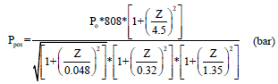
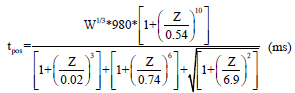
where Ppos - peak incident pressure, tpos- positive phase duration, Po – Peak positive pressure, W - charge weight presented in terms of the mass of the equivalent Trinitrotoluene (TNT) in kilograms, Z - scaled distance expressed as
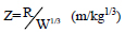
where R= Radial distance in meter, W = Charge weight in terms of the equivalent mass of TNT, pressure wave exerted from the blast load with respect to any time can be expressed as follows
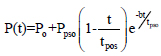
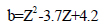
where t = time measured after tA; and b = unitless wave decay parameter
The peak reflected pressure can be computed using the coefficient of reflection (Cr)

2.2. Torsion
For the high-rise frame structure exposed to wind load, unsymmetrical structure leads to torsional effect. The torsional irregularity indices considering due to eccentricity along X and Y directions expressions are as follows


where ekx - eccentricity along the x-direction, eky - eccentricity along the y-direction, (Xm, ym) and (Xr, yr) are the coordinates of the center of mass and center of rigidity respectively.
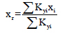

where Kxi and Kyi and are the lateral stiffness of column i along with the global X and Y directions. (Xi, yi) represents the coordinate of column i of the relative reference frame.
Torsional radius along X and Y directions are calculated by using the following equations
The torsional radius of gyration of a particular floor is given below

where mi is the lumped mass at a radial distance di from the Center of Mass (CM).
The aspect ratio and stiffness ratio along two-directional are shown below


where b and a are the width of the frame along x and y directions respectively. M is the center of mass, mass of the moment of inertial are shown below

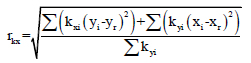
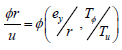
The torsional relative effect index is calculated below ϕ&r are the torsional angle and radius of gyration of the floor, u is the centroid displacement.  is the torsional index which gives the relationship between structural torsion and structural translation
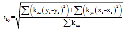
where  represents the eccentricity ratio along the direction Y and
  is the uncoupled translations torsion period ratio.
2.3. Pressure Impulse Curve
The pressure impulse curve is the important response of the MRF with blast load. Pressure impulse curves are calculated by different energy-based methods, analytical methods, experimental methods. Energy-based method is a simple and accurate method for obtaining the pressure impulse curve. The following equations represent the procedure of plotting the pressure impulse curve [63].


where I – Impulse, β - load pulse shape factor = 0.5 for triangular load, Einput – represents the input energy and Einput_rate - Input energy rate. The dimensionless terms for the two axes are defined as follows

where  represents the pressure and impulse of the curve
2.4. Single Slip Load (SSL) Friction Damper
Fig. (1) represents the hysteretic behaviour of the friction damper of the single slip load. The friction coefficients in their interface and force clamping of moving parts are the parameters depending on single slip load capacity. The slip load can be expressed as
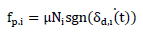
Where fp,I is the passive load, Ni is the constant, preloaded clamping force, µ is the friction coefficient, and sgr indicates the direction of motion.
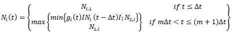
where m=1,2, 3…., n (i.e.∆t is the time at the end of every interval of decision) and Ni (t - ∆t) is the clamping force.
2.5. Double Slip Load (SSL) Friction Damper
Fig. (2) shows the hysteresis behavior of the DSL (double slip load) damper. The axial force of the brace element equals P1, which is known as the first slip load. The maximum amount of first slippage is ∆. The first slippage will be 0.5-time ∆. The axial force of the brace element will be larger when the blast load input reaches the maximum, then the force of the brace element reaches P2 is known as the second slip load.
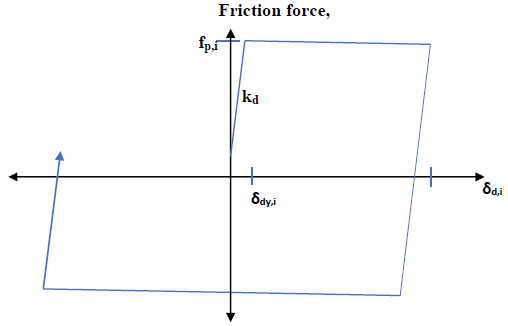
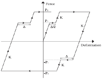

Fig. (3) shows the flow chart of software analysis to obtain the control force in the MRF by single slip load damper and double slip load damper. The assemble of the structural model is created includes stiffness, mass, and stiffness, then apply blast load in terms of the pressure-time curve. The response is calculated by using the Multi adaptative pushover analysis. The responses are local and global responses are calculated. The control force exerted by the single slip load is applied to the frame, if the response from the frame exceeds the limit double slip load damper exerts the force. In the double slip damper, if the force exerted is to control the response of the frame is sufficient then the slip load P2 is sufficient. But, if the double slip damper force is not sufficient then two slip load acts, that is P1 and P2. The force exerted by the damper to the frame is sufficient to control the response otherwise modifies the stiffness. The double slip load damper works on the principle of the hysteresis loop.
2.6. Modelling System with Blast Load
2.6.1. Modelling of the System with Blast Load
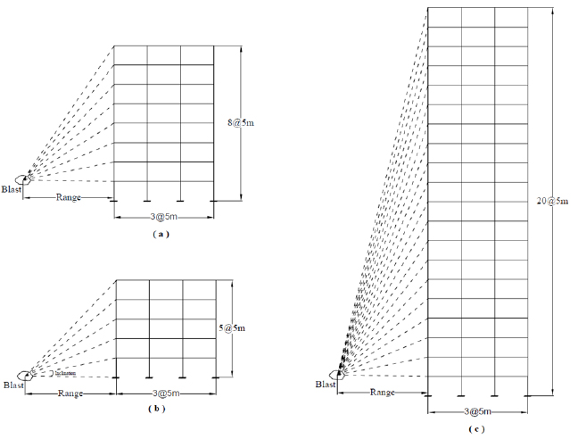
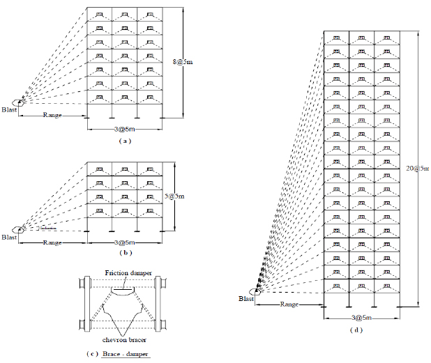
Fig. (4) shows the MRF exposed to blast load. It consists of the three frames that is low rise, mid-rise, and high-rise frames of the 4 storey, 8 storey and 20 storey frames. Each frame has three bays of each bay as 5m, height of each floor is 5m.
The vibration properties, frame properties, and weight in each floor are used in the study as shown in Tables 1, 2 and 3 respectively.
| Frame | Period (sec) | Effective Modal Mass (%) | ||||||
|---|---|---|---|---|---|---|---|---|
| Mode 1 | Mode 2 | Mode 3 | Mode 4 | Mode 1 | Mode 2 | Mode 3 | Mode 4 | |
| 5 Story | 1.09 | 0.38 | 0.21 | 0.13 | 79.41 | 12.47 | 3.96 | 3.27 |
| 8 Story | 1.42 | 0.56 | 0.23 | 0.23 | 73.5 | 12.65 | 5.25 | 2.15 |
| 20 Story | 1.93 | 0.72 | 0.42 | 0.35 | 70.69 | 12.54 | 4.76 | 2.92 |
| MRF | Floor |
Mass (103 kg) |
Stiffness (kN/m) |
Damping (kNs/m) |
|---|---|---|---|---|
| 5-Storey | 1 | 21.213 | 31860 | 2100 |
| 2 | 21.213 | 31860 | 2100 | |
| 3 | 21.213 | 31860 | 2100 | |
| 4 | 21.213 | 31860 | 2100 | |
| 5 | 21.213 | 31860 | 2100 | |
| 8-Storey | 1 | 21.213 | 31860 | 2100 |
| 2 | 21.213 | 31860 | 2100 | |
| 3 | 21.213 | 31860 | 2100 | |
| 4 | 21.213 | 31860 | 2100 | |
| 5 | 21.213 | 31860 | 2100 | |
| 6 | 21.213 | 31860 | 2100 | |
| 7 | 21.213 | 31860 | 2100 | |
| 8 | 21.213 | 31860 | 2100 | |
| 20-Storey | 1 | 2041 | 172255 | 27318 |
| 2 | 2011 | 156541 | 24826 | |
| 3 | 2011 | 131956 | 20927 | |
| 4 | 2011 | 119869 | 19010 | |
| 5 | 2011 | 111175 | 17631 | |
| 6 | 2011 | 102413 | 16241 | |
| 7 | 2011 | 913068 | 14480 | |
| 8 | 2011 | 818123 | 12974 | |
| 9 | 2011 | 761873 | 12082 | |
| 10 | 2011 | 713378 | 11313 | |
| 11 | 2011 | 668616 | 10603 | |
| 12 | 2011 | 622953 | 9879 | |
| 13 | 2011 | 560090 | 8882 | |
| 14 | 2011 | 512098 | 8121 | |
| 15 | 2011 | 473719 | 7513 | |
| 16 | 2011 | 436525 | 6923 | |
| 17 | 2011 | 398817 | 6325 | |
| 18 | 2011 | 359101 | 5695 | |
| 19 | 2011 | 315938 | 5010 | |
| 20 | 2011 | 271092 | 4299 |
| Sl No | Load on the Floor | Magnitude |
|---|---|---|
| 1 | Dead load on intermediate floor | 600 kg/cm2 |
| 2 | Live load on intermediate floor | 250 kg/cm2 |
| 3 | Dead load on roof | 550 kg/cm2 |
| 4 | Live load on roof | 150 kg/cm2 |
| 5 | Steel Yield stress | 2400 kg/cm2 |
| Sl No | Parameter | Value |
|---|---|---|
| 1 | Yielding stress Fy | 235.36 MPa |
| 2 | Modulus of Elasticity | 205.94 GPa |
| 3 | Strain hardening | 3% |
| 4 | Initial stiffness | Plasticity |
| 5 | Base condition | Fixed |
2.6.2. Blast Load Modeling of the System
Surface blast load acting on the frame is analyzed. The pressure is calculated in the above sections. The behaviour of the steel frames and blast load parameters are shown in Tables 4 and 5.
| Sl No | Parameter | Symbol | Magnitude |
|---|---|---|---|
| 1 | Weight | W | 2000 TNT(Trinitrotoluene)* |
| 2 | Range | R | 10m |
| 3 | Scaled Distance | Z | 0.793 m/kg1/3 |
| 4 | Peak positive pressure | Pso | 78.3 kPa |
| 5 | Time of arrival | tα | 81 sec |
| 6 | Length of wave | Lw | 20 m |
| 7 | Negative phase durations | to | 25 sec |
| 8 | Positive impulse | is | 135 kPa -sec |
| 9 | Peak reflected pressure | Pr | 221 kPa |
| 10 | Reflected impulse | ir | 221 kPa sec |
2.6.3. Friction Damper with MRF
Friction dampers are installed in each floor as shown in Fig. (5). Table 6 shows the response parameter of the MRF.
| Sl No | Parameter | Equation | Variables |
|---|---|---|---|
| 1 | Drift ratio | 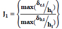 |
 = Drift ratio at level i, for controlled = Drift ratio at level i, for controlled |
| 2 | Acceleration |  |
 = acceleration relative to the ground and control = acceleration relative to the ground and control |
| 3 | Base shear |  |
 = Shear force at the base of the frame = Shear force at the base of the frame |
| 4 | Average Drift |  |
 = Average of simultaneous drift in the building at time of maximum drift of level i. = Average of simultaneous drift in the building at time of maximum drift of level i. |
The governing equation of motion for n-degrees of freedom-controlled frame subject to blast load can be written as
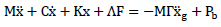
where x is the displacement vector,  and
and  represents the first and second time derivatives of x, respectively;F= [fd1,fd2,……..fdn]T and g are control force vector and the acceleration due to blast load, respectively; M,C and K are mass, damping, and stiffness matrices respectively;
  is a mass of zeros and ones, where one will indicate the damped force being applied and
  is the influence coefficient vector and Pb is the pressure exerted due to blast load.
Equation (xx) can be further transformed to state-space representation as:
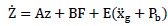
where z is the state vector of structure and contains the relative of ground displacement and velocity of each floor; A denotes the system matrix composed of structure mass, damping, and stiffness matrices; B represents the distributing matrices of control forces; and E represents the distributing matrices for excitation.
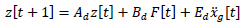
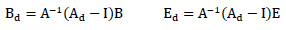
where t denotes the time step; Ad =eAΔt represents the discrete-time system matrix with Δt as the time interval. The constant-coefficient matrices Bd and Ed are discrete-time counterparts of the matrices B and E that may be written as
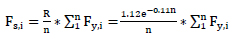
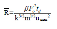
where R is the optimum slip load ratio; n is the number of floor and Fs,i and Fy,i is slip load and shear strength.
The average slip load ratio is obtained from the following equations
where Favgis the average slip load ratio.
3. RESULTS AND DISCUSSIONS
3.1. Five Storey Frame
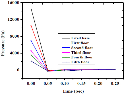
Fig. (6) shows the blast load acting on the five-storey frame. The maximum pressure occurs of 15 kPa at fixed base and the minimum pressure occurs of 2 kPa at the fifth floor.
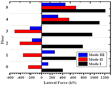
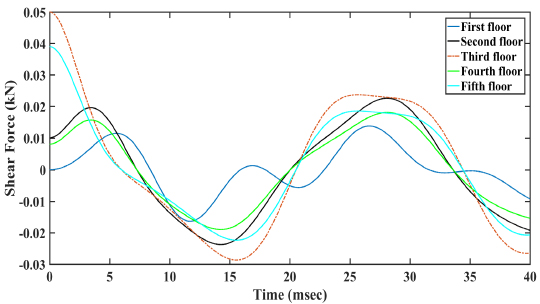
The lateral force occurs at -500 kN to 1200 kN. Fig. (7) shows the shear force acting on the five-storey frame. The maximum shear force occurs of 0.05kN at the third floor and the minimum shear force occurs at 0.01 kN at the first floor.
| Sl.No | Storey | Component | Bare | FSSL | FSDL |
|---|---|---|---|---|---|
| 1 | Fixed Base | Accleration (m/sec2) | 5.3 | 4.0 | 3.9 |
| 2 | Velocity (m/sec) | 4 | 3.25 | 2.8 | |
| 3 | Displacement (m) | 0.09 | 0.075 | 0.05 | |
| 4 | Fifth Floor | Accleration (m/sec2) | 1 | 0.8 | 0.75 |
| 5 | Velocity (m/sec) | 0.5 | 0.45 | 0.42 | |
| 6 | Displacement (m) | 0.03 | 0.025 | 0.022 |
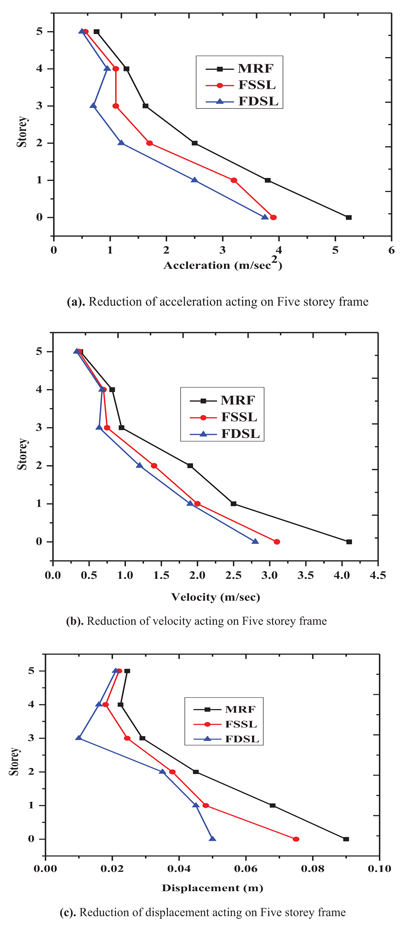
Fig. (9) shows the reduction of the response of five storey structure by using friction dampers.
Figs. (10 and 11) show the increase of the pressure impulse curve in 2D and 3D of five storey frame by using single and double friction damper.
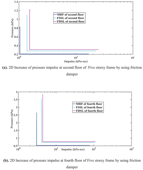
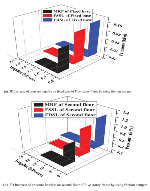
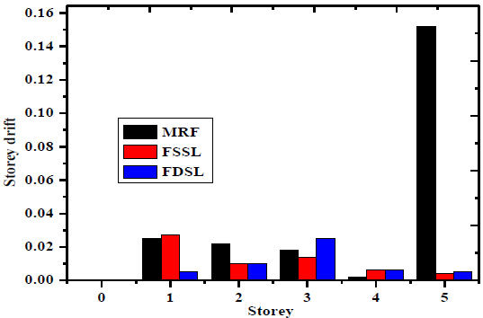
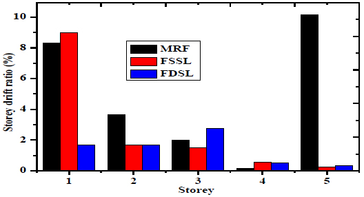
Fig. (12) shows the storey drift of the five-storey frame. The maximum storey drift occurs at fifth floor of 0.15 of MRF, 0.0095 and 0.0099 of FSSL and FDSL. The minimum storey drift occurs at fourth floor of 0.0095 of MRF, 0.0158 and 0.0195 of the FSSL and FDSL. Fig. (13) shows the storey drift ratio of the five-storey frame. The maximum storey drift ratio occurs at first floor of 8% of MRF, 9% of the FSSL and 1.8% of the FDSL. The minimum storey drift ratio occurs at fourth floor of 0.8% of MRF, 0.95% of the FSSL and 1% of the FDSL.
3.2. Eight Storey Frame
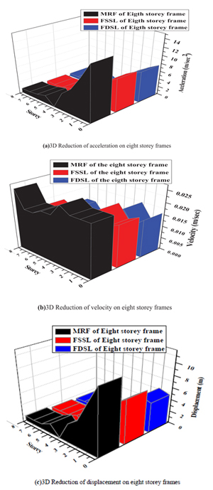
Fig. (14) represents three dimensions of the reduction of response of eight storey frame by friction damper. The maximum displacement occurs at fixed base of the MRF is 8m and is reduced to 6m and 5m of the FSSL and FDSL respectively. The maximum velocity occurs at fixed base of the MRF is 0.025m/sec and is reduced to 0.017m/sec and 0.015m/sec of the FSSL and FDSL respectively. The maximum acceleration occurs at fixed base of the MRF is 10m/sec2 and is reduced to 8m/sec2 and 7.5m/sec2 of the FSSL and FDSL respectively.
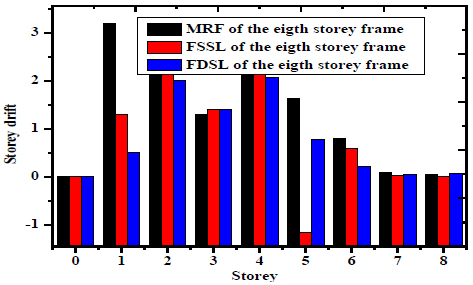
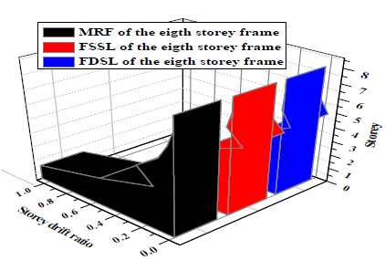
Figs. (15 and 16) shows the two- and three-dimensions reduction of the storey drift of the eight-storey frame. The maximum storey drift occurs at fourth floor of 2.1 of the MRF and is reduced to 2.05 and 2 of the FSSL and FDSL respectively. The minimum storey drift occurs at fixed base of 0.05 of the MRF and is reduced to 0.04 and 0.04 of the FSSL and FDSL respectively.
3.3. Twenty Storey Frame
3.3.1. Along x Direction
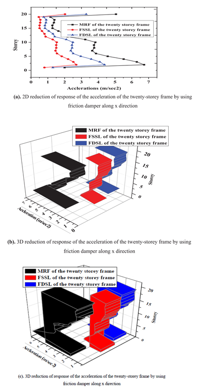
Fig. (17) represents reduction both 2D and 3D of the acceleration of the twenty-storey frame by using friction damper. The maximum acceleration occurs at third floor of 7m/sec2 of the MRF frame and the acceleration is reduced to 4.5m/sec2 and 2.8 m/sec2 of the FSSL and FDSL respectively.
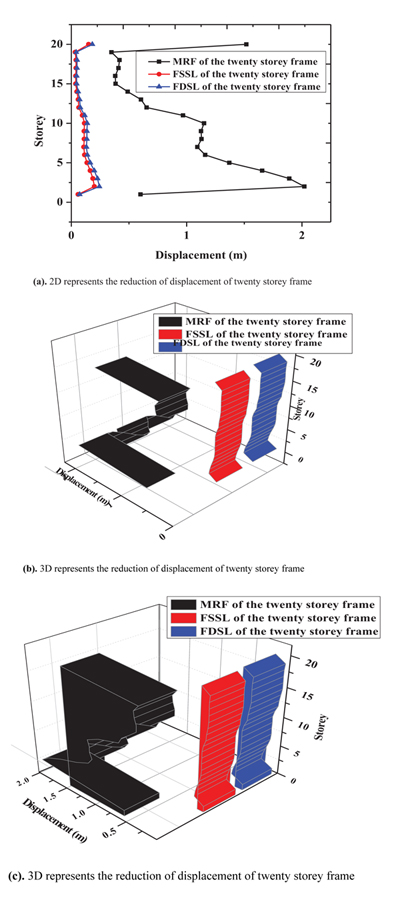
Fig. (18) represents the reductions of the displacement of the twenty-storey frame along x direction in 2D and 3D. The maximum displacement occurs at third floor of 2m of the MRF and is reduced to 0.25m and 0.2m of the FSSL and FSDL respectively.
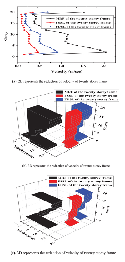
Fig. (19) represents the 2D and 3D of the reduction of the velocity of the twenty-storey frame along x direction by using friction damper. The maximum velocity occurs at third floor of 2m/sec of the MRF and is reduced to 0.8m/sec and 0.5m/sec of the FSSL and FSDL respectively.
3.3.2. Along y Direction
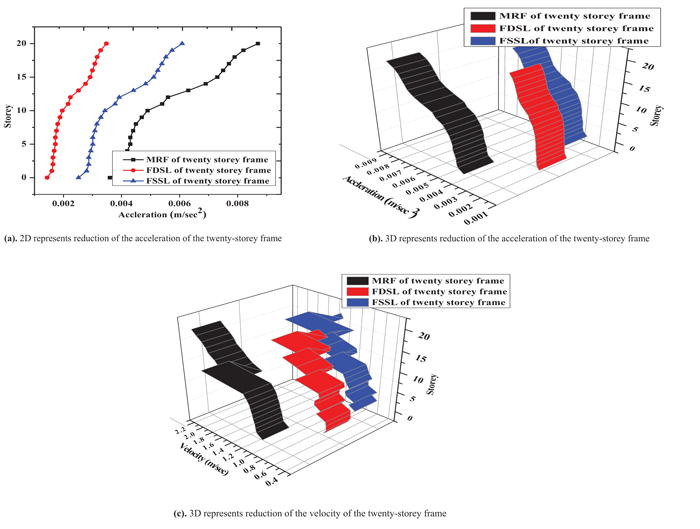
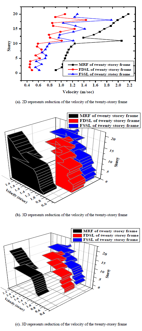
Fig. (20) shows two dimensional and three dimensional representing the reduction of the acceleration of the twenty-storey frame along y direction. The maximum acceleration occurs at twenty storeys of 0.009 m/sec2 of the MRF and is reduced to 0.006 m/sec2 and 0.003 m/sec2 of the FSSL and FSDL respectively. Fig. (21) shows two dimensional and three dimensional representing the reduction of the velocity of the twenty-storey frame along y direction. The maximum velocity occurs at twenty storeys of 2.2 m/sec of the MRF and is reduced to 1.3 m/sec and 1 m/sec of the FSSL and FSDL respectively.
Average performance and torsional moment of twenty storey frame are shown in Tables 8 and 9 respectively.
| Sl No | Response Parameter | FSSL (Mode) | FSDL (Mode) | ||||||
|---|---|---|---|---|---|---|---|---|---|
| I | II | III | IV | I | II | III | IV | ||
| 1 | Drift ratio | 0.8345 | 0.8210 | 0.7854 | 0.6845 | 0.7582 | 0.7412 | 0.7102 | 0.6845 |
| 2 | Acceleration | 0.642 | 0.689 | 0.624 | 0.598 | 0.645 | 0.660 | 0.610 | 0.690 |
| 3 | Base shear | 0.5480 | 0.5210 | 0.569 | 0.610 | 0.564 | 0.520 | 0.510 | 0.505 |
| 4 | Average Drift | 0.678 | 0.680 | 0.660 | 0.610 | 0.64 | 0.6215 | 0.6102 | 0.604 |
| Sl No | Floor | Torsional moment along x direction | Torsional moment along y direction |
|---|---|---|---|
| 1 | First | 121 | 85 |
| 2 | Second | 120 | 88 |
| 3 | Third | 122 | 90 |
| 4 | Fourth | 121 | 95 |
| 5 | Fifth | 120 | 96 |
| 6 | Sixth | 112 | 98 |
| 7 | Seventh | 118 | 101 |
| 8 | Eight | 124 | 110 |
| 9 | Ninth | 126 | 120 |
| 10 | Tenth | 128 | 112 |
| 11 | Eleventh | 129 | 116 |
| 12 | Twelve | 134 | 112 |
| 13 | Thirteen | 138 | 114 |
| 14 | Fourteen | 142 | 116 |
| 15 | Fifteen | 145 | 124 |
| 16 | Sixteen | 149 | 108 |
| 17 | Seventeen | 180 | 104 |
| 18 | Eighteen | 190 | 105 |
| 19 | Nineteen | 195 | 109 |
| 20 | Twenty | 195 | 109 |
CONCLUSION
The low rise, mid-rise, and high rise MRF with blast load. The response was calculated by using adaptive-based pushover analyses. The three-mode shapes are considered in the analyses of the frame. The different response parameters are displacement, velocity, accelerations, pressure impulse curve, normalized pressure impulse curve, storey drift, storey drift ratio are studied. The response is controlled by using a single slip load friction damper (FSSL) and double friction slip damper (FSDL). The following conclusions are drawn:
(1) The blast load performance of the MRF models was improved significantly under both single slip load damper and double slip load damper.
(2) The 20% and 30% reductions of the accelerations in all the frames by using a single slip load damper and double slip load damper.
(3) The extreme floors reaction of the DSL prepared dampers is disseminated more consistently along the height of the building models.
(4) As per this limited study, the most advisable buildings to be equipped with the proposed DSL damper are the mid-rise building models.
(5) The interstorey driftsare reduced to 30%, 60% by using a single slip load damper and double slip load damper, respectively.
(6) The results of the pressure impulse curve of the MRF, FSSL & FSDL are obtained by energy-based pressure impulse curve method.
(7) Performance of the blast load with highrise structural frame is analyzed by considering the torsional effects and response in two dimensions effects parameter.
(8) The 28% and 35% increase of the pressure and 25% and 30% increase of the impulse will not cause failure to the structural frame by using FSSL and FSDL.
(9) Shear force will be maximum at first floor of the five storey frame exposed to blast load and minimum occurs at fifth floor
(10) The maximum torsional moment occurs at twenty floor of 195 kNm along x directions and minimum occurs at lower storey along y directions of first floor of 85 kN m.
(11) The maximum lateral force occurs at first mode in eight floor and minimum lateral force occurs at first floor in the mode I.
(12) The displacement will be maximum along x directions in the eight-storey frame.
CONSENT FOR PUBLICATION
Not applicable.
AVAILABILITY OF DATA AND MATERIALS
Some or all data, models, or code that support the findings of this study are available from the corresponding author [E.N.F] upon reasonable request.
FUNDING
None.
CONFLICT OF INTEREST
The authors declare no conflict of interest, financial or otherwise.
ACKNOWLEDGEMENTS
None.

