All published articles of this journal are available on ScienceDirect.

Determination of Creep Behavior of Concrete Beams Made with Rice Husk Ash
Abstract
Background:
Creep in concrete is a long-term deformation under sustained loading. It is influenced by many factors, including constituent materials, environmental conditions, among others. Whenever there is an alteration in the convectional concrete preparation process, the creep characteristics need to be realistically assessed. In the present construction, rice husk ash has been used for partial replacement of cement in concrete production. This is because its properties of both tensile and compressive strength in concrete have been tested and found comparable with plain concrete. However, durability characteristics such as creep, which take place in the long run, have not been realistically assessed. Therefore, it is important to study the creep of rice husk ash concrete, which will further help in the development of a creep prediction model for such concrete for use by design engineers.
Objectives:
Rice husk ash was used as supplementary cementitious material in concrete, and the creep behavior was studied with the aim of producing a creep prediction model for this concrete.
Methods:
The cement was replaced with 10% of rice husk ash in concrete with a design strength of 30MPA. Reinforced concrete beams were cast and loaded for flexural creep 35 days after casting. The loading level was 25% of the beam’s strength at the time of loading. The creep observation was done for 60 days. The rice husk used was obtained locally from Mwea irrigation scheme in Kenya. The experiments were carried out in our school laboratory at Jomo Kenyatta university of Agriculture and Technology.
Results:
The creep strain data of rice husk ash concrete beams was obtained with the highest value of 620 micro strain for 60 days. The results were used to develop a creep prediction model for this concrete.
Conclusion:
A creep prediction model for rice husk ash concrete has been developed, which can be adopted by engineers for class 30 of concrete containing rice husk ash at a 10% replacement level.
1. INTRODUCTION
1.1. Background of Study
Environmental engineers and scientists are concerned with environmentally sustainable products due to the exponential increase in industrial activities over the recent decades, according to K. Roy et al. [1]. Therefore, the need to research materials that can be used to replace constituents of concrete cannot be overemphasized. This is due to the depletion of these natural constituents and also demand for improved concrete properties. Production of cement, which is the binder in concrete, emits a lot of CO2 in the atmosphere, with 1 ton of cement emitting 0.9 ton of CO2 as shown by C. Chen et al. [2]. In addition, cement production is extremely energy and resource intensive, with 1.5 tons of raw materials required for a ton of production of cement, according to K. Roy et al. [1]. A potential solution in reduction of CO2 emission from the cement industry and reduction of cement required in construction is to add supplementary materials in replacing the cement content. These materials include industrial (steel slag and fly ash) and agricultural by-products, which help in the reduction of greenhouse gases, according to L.Rajamony Laila et al. [3]. Supplementary cementitious materials (SCMs) are materials that are used to partially replace cement in the production of concrete. These materials possess pozzolanic activity, and thus they can react with the calcium hydroxide produced during cement hydration to form an additional cementing gel. Studies have proved that the use of these supplementary cementitious materials to replace cement reduces the amounts of carbon dioxide released to the atmosphere by 17%. This is because none of the material is derived from raw materials and relatively little carbon dioxide is associated with their processing according to M. Tyrer et al [4]. Feasibility studies into use of these wastes in concrete have also been found to improve the strength properties of concrete and reduce the alkali-silica reaction on top of reducing greenhouse effect according to L. Rajamony Laila et al. [5]. Rice husk ash (RHA) is major agricultural by-product from food crop paddy. For every four tons of rice produced, a ton of rice husk ash is produced. The husk is disposed by either dumping in open area near the milling site or on the roadside to be burnt. Burning rice husk has been used for production of steam, generating about 15-20% of the ash by weight. The ash being very light is carried by wind and water in its dry state. It is difficult to coagulate and thus contributes to air and water pollution according to Barrack M [6]. Cumulative generation of ashes require a large space for disposal. This has led to environmental concerns hence the need for potential re-use. Therefore, rice husk ash (RHA) is increasingly being used as a supplementary cementitious material to replace cement in concrete production as it is a pozzolan. RHA concrete has been found comparable to normal concrete in terms of structural and mechanical behavior up to 25% level of replacement.
1.2. Studies on Concrete with Rice Husk Ash
The strength of concrete with RHA replacements of 10 and 15% revealed that the addition of RHA in concrete increased cohesiveness and stiffness of the mixture due to the fineness of RHA. Increased RHA lowered the compressive strength of concrete; however, with 10% replacement, the strength variation was 1-2.5% hence a recommendation of 10% by A.Siddika et al. [7]. Another study by Josephim Alex et al. on the variation of RHA in concrete from 0,10,15, and 20% revealed that 10% replacement had a remarkable percentage of strength gain with 7.8% as compared to plain concrete [8]. Also, incorporating RHA in concrete was found to contribute to low ratios of chloride ion penetration up to 928 coulombs with 25% replacement, as shown by S.A Zareei et al. [9]. The current use of RHA in concrete has an emphasis on strength characteristics which is tested at 28 days.
This is in conformity with the current civil engineering practice of designing ordinary RC structures whereby a major focus is given to ULS (Ultimate Limit State), i.e., load-bearing capacity. Simplistic methods are often employed for the second limit state, i.e., SLS (Serviceability Limit State). This latter state covers criteria arenecessary for the functional and intended purpose of the structure and user’s comfort. The most commonly used criterion for SLS is ultimate deflection, hence keeping other conditions such as criteria on crack width, structural vibrations, among others, unresolved. Failure to take into account all SLS criteria in design and construction phases may only save a certain amount of money at the initial phase; however the same or even more will be dispensed after several years for inevitable maintenance, according to Havlasek et al. [10].
Creep in concrete is defined as deformation under a sustained load that takes place in the direction of the load. Aggregates usually record very little creep, but they do influence the creep through a restraining effect on the magnitude of creep. The paste is responsible for creep. Quality and amount of paste are important factors in creep. Other additional factors influencing creep are water content curing conditions, relative humidity, specimen sizes, etc. In general, the creep rate of concrete increases with applied stress, as shown by A.A. Olayinka et al. [11].
1.3. Creep in Concrete
The use of SCMs in concrete affects the strain behavior of such concretes. This is because the SCMs modify the pore size distribution and characteristics of interferes. As reported, the addition of metakaolin reduces creep, whereas Blast furnace slag increases the creep, as shown by M. Shariq et al. [12]. Creep of RHA concrete studied on cylinders showed a decrease in creep with an increasing % of RHA. This was attributed to the pore microstructure of RHA as smaller capillary pores were observed on RHA concrete as compared to plain concrete. RHA addition in concrete made it denser and impervious hence lower creep values as shown by Z. Hai He et al. [13].
Creep does not cause short-term failure in concrete; however, it leads to redistribution of internal forces and deformation of concrete structures in the long run. The total strain in concrete, including load-induced strain, becomes significant when determining whether concrete reaches a failure state and becomes much more critical when concrete undergoes creep in tension with shrinkage due to the low-strain carrying capacity of concrete in tension. Once the tensile strain reaches the ultimate value in concrete, cracking occurs, seriously affecting durability and serviceability. Bending creep has a crucial effect on gradual increases of deflection of concrete flexural members such as slab and beam, according to S. G. Kim et al. [14].
In practice, engineers predict creep strain using standard codes or available models developed in temperate countries. These creep models include ACI 209 (by American concrete institute), CEB-FIB (by Euro-international concrete comm-ittee), B3, and GL 2000. These models were developed by curve fitting of test results according to M. H. Kabir et al. [15].
Creep of concrete containing Iranian pozzolans showed that each pozzolan had an effect on the creep of concrete. Model results from creep prediction models were compared with experimental results; it was found that experimental results were higher than predicted values; however, the 28-day estimation model (short-term data model) gave a better prediction, according to P. Ghodhousi et al. [16]. Creep of concrete containing varying ratios of reinforcement showed that the reinforcement inhibits creep. Comparisons of the results with models showed a similar trend even though the values differed. The ACI model proved to be more accurate, and it was modified in order to incorporate the influence of reinforcement ratio, according to G. Sun et al. [17].
As has been documented, the creep of concrete changes when mineral admixtures have been used. Incorporation of concrete creep effect in the analysis of structures is deemed necessary. Once the creep behavior of concrete is understood, adjustments should be made in the design to cater for the same, according to M. Shariq et al. [12]. Furthermore, variation of results between model predictions (of most commonly used creep prediction models) and experimental results shows that the models have not taken into account the effect of mineral admixtures such as rice husk ash in concrete; hence modifications are required to the original equation.
Based on the above discussion and having found that RHA is a suitable SCM, an investigation on the creep of RHA concrete beams is presented in this paper. The creep is studied experimentally, and the results are used to develop a formula for creep prediction of 30MPa concrete beams made with 10% rice husk ash as SCM.
2. EXPERIMENTAL SET-UP
The raw materials used in this investigation were obtained locally in Kenya. Ordinary Portland cement grade 42.5 was used as a binder and rice husk ash obtained from the Mwea rice irrigation scheme was used as an SCM. River sand was used as fine aggregate and crushed stone of 5-20 mm as coarse aggregates. Portable water was used for mixing and curing throughout the study.10% RHA was used to partially replace cement. The mix proportions for 30 MPa concrete are shown in Table 1 below.
|
RHA % |
Cement (kg/m3) |
Water content(kg/m3) |
RHA (kg/m3) |
FA (kg/m3) |
CA (kg/m3) |
W/B ratio |
Slump mm |
|---|---|---|---|---|---|---|---|
| 0 | 375 | 210 | 0 | 648 | 1153 | 0.56 | 60 |
| 10 | 354 | 205 | 39 | 648 | 1153 | 0.52 | 60 |
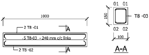
The study aimed to determine creep in concrete beams whereby cement has been partially replaced with 10% RHA. The reinforced concrete beams were designed whose cross-section was 100mm x 150mm x 1000mm. The combination of high tensile strength reinforcing steel with high compressive strength of concrete formed a stiffer and stronger structural composite in which transfer of internal actions took place between concrete and steel, with the transfer taking place at the interface of two materials, according to L. Dowe et al. [18]. However, the reinforcement ratio was 1.3%, suggesting that its effect in restraining creep couldbe neglected, according to G.Sun et al. [17]. Four beam specimens were prepared, two for creep and two for shrinkage. Details of sectional reinforcements are shown in Fig. (1).
Wooden formwork was fabricated for the beams according to the determined sizes. Afterwards, the casting of beams, cubes, and cylinders was done. The cube specimens were cast in 100 mm x 100 mm x100 mm in steel molds, whereas the cylinders were cast in 100 mm diameter and 200 mm height also in steel molds. Cubes and cylinders were demolded after 24 hours, and curing was done by fully immersing in water. The beams were demolded after 4 days and covered with hessian cloth, and fully moisturized by sprinkling until 28 days.
The compressive and tensile strength tests on cubes and cylinders respectively were done at 7 days and at the time of loading, which was 35 days after casting. The results are shown in Table 2 below.
|
Slump (mm) |
Age a loading (t0 days) |
Compressive strength (MPa) |
Tensile strength (MPa) |
||
|---|---|---|---|---|---|
| 7 days | At loading | 7 days | At loading | ||
| 47 | 35 | 22.8 | 39.5 | 1.8 | 3.1 |
Strain gages of 30mm gauge length attached to the surface of beam specimens were used to measure the strains. On the creep beams, strain gauges were attached at the top and bottom mid-point and on the opposite sides of shear, as shown in Fig. (2a) below. Also, a dial gauge was placed at the bottom of each beam to monitor the growth of deflection with time. For the shrinkage beams, strain gauges were attached at the top and bottom mid-points. Strain gauges were connected to 2 data loggers with 10 channels each. These strain gauges were installed on day 35.
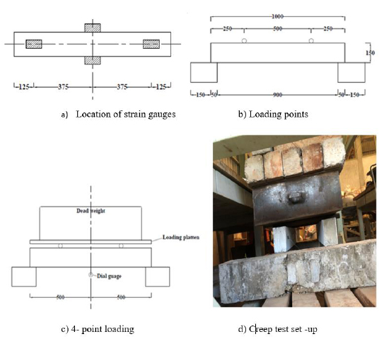
A concentrated load of 0.3tonnes was applied at each point 250 mm from the supports to develop a 4-point bending behavior, as shown in Fig. (2b). The dead load was made up of waste concrete elements in the laboratory heaped one on top of each, as shown in Fig. (2c and d) below. This loading ensured a constant load throughout the test duration. The load induced an initial flexural normal stress of 0.74 MPa at the bottom and top surfaces within the loading points. This load was equivalent to 24% of the beam’s strength at the time of loading. Two beams remained unloaded for shrinkage.
The total strains of beams under load were measured at the same location as the shrinkage beams (i.e., the top and bottom midpoints). The creep strain was obtained by subtracting beam shrinkage and measured instantaneous strain from total strain. The creep loading and observation were carried for a duration of 60 days.
3. RESULTS AND DISCUSSION
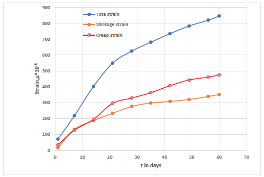
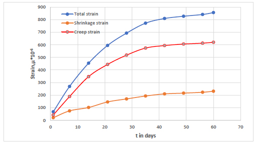
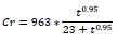
The average of total shrinkage and creep strain versus time (t) at the top and bottom surfaces are shown in Figs. (3 and 4) below. The discussion follows below on each of the aspects of the data in the aforementioned figures.
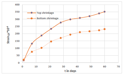
3.1. Shrinkage
The trends in shrinkage and creep for both surfaces were similar, with a steep increase at early ages followed by a gentle increase at later ages, as shown in Fig. (5) below. However, the value of creep is more than twice that of shrinkage. In both the creep and shrinkage, growth continues with time but at a decreasing rate [12, 17].
The shrinkage strain is largest on top as compared with the bottom surfaces as drying takes place at the surface. The shrinkage reported is drying shrinkage, which is a continuous process when concrete is subjected to drying conditions. This shrinkage does not result from the loss of free water but the loss of the water held in gel pores. On exposure to drying, the gel water is lost progressively over a long time. The unrestrained paste loses its volume; hence it shrinks [19]. The rate of drying shrinkage decreases rapidly with time. It is observed that at 60 days, shrinkage strain contributes to almost 40% of the total deformation. Shrinkage causes unsightly cracks in concrete, which make the concrete creep more as it creates points of weakness
This study shows that the drying shrinkage is an inherent property of concrete that cannot be eliminated; however, its magnitude can be reduced to avoid damage in concrete. The magnitude can be reduced by the use of low heat Portland cement or pozzolanic cement as these have a higher capacity to withstand volume changes without cracking, as opposed to ordinary Portland cement [19].
Therefore, in experiments of bending creep strains, there is a need to properly account for shrinkage variation within the beam depth, which is mainly caused by compaction of concrete and bleeding during casting work.
3.2. Creep
The bottom creep is higher than the top creep, as shown in Fig. (6) below. This could be explained by higher shrinkage strains at the top since the magnitude of total strain is almost the same for both surfaces.
The rate of creep is much faster for the of early age (up to 21 days) than at later ages. At the age of t > 35 days, the rate of increase of creep tends to be stable. It is also observed in the 56% of the observed 60 days is achieved withing 14 days of sustained loading. The maximum creep for the 60 days was 620 microstrain (0.00062 mm/m). This creep strain being more than 400 microstrain is considered significant in concrete and cannot be ignored [20]. The creep strain in this experiment reached the secondary stage or the steady state creep. The creep strain and drying shrinkage have similar trends, however the value of creep is more than twice that of shrinkage.
Creep of concrete is largely induced by change in internal relative humidity of the concrete matrix as pore water distribution changes under loading from the region of high to low stress. This results in the transfer of load from the liquid phase to the surrounding solid. Under sustained load, the pressure of capillary water gradually disappears, followed by gel pore water. Therefore, the pressure on intercrystallite adsorbed water continues to act during the entire loading period. Hence the gradual decrease in the magnitude of creep [19].
4. CREEP PREDICTION
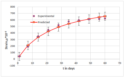
It is the interest of this study to predict the short-term creep behavior of concrete beams made with RHA. The prediction of creep is determined using experimentally obtained results for the bottom creep by fitting the experimental results of creep to the original creep expression below [15];

whereby Cr is creep strain (micro strain)
t is time (days)
a and b are constants
Fitting of experimental results into the creep model by non-linear regression yields this new equation;
whereby 963 is a factor that relates to material compo-sition, size of the concrete section, and the environmental conditions.
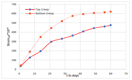
Using the above formula, the theoretical creep strain values are found, which are plotted against the experimental values as shown in Fig. (7) below.
As shown in the figure above, the fitting of creep strain becomes better with a correlation coefficient of 94.78%. Also, the upper and lower bound of the error bar on predicted values lies within the limit of experimental values to show that the prediction is good. Hence the modified prediction model matches better with experimental results for 30 MPa concrete made with 10% RHA. The formula may need to be adjusted for different strengths and % of RHA.
This model can be incorporated in the design of concrete structures containing rice husk ash but with a limitation of early age prediction up to 28 days and a loading rate of about 25%. For 10% RHA in concrete, the model predicts that 76% of the ultimate creep takes place in the 60 days of loading, whereas 95% of the ultimate creep can be reached at 350 days of loading.
CONCLUSION
In this study, grade 30 concrete beams with 10% RHA were prepared and tested for creep. The creep strain was measured for 60 days. From the study, the following conclusions can be made;
(a) The beams, having met the minimum required strength at 28days (39.5 MPa > 30 MPa), were loaded for creep testing and the maximum creep obtained for 60 days of loading was 620 micro strains. Primary creep, i.e., rapidly increasing, was experienced up to 35 days of loading, and afterwards secondary creep is the stable rate set in up to the end of the experiment. Tertiary creep, which is rapid increase until failure was not reached. The creep strain obtained being more than 400microstrains is considered significant in concrete and cannot be ignored in structural design.
(b) The maximum shrinkage observed for 60 days of testing was 351 micro strains.
(c) A creep prediction model for rice husk concrete was developed, which can be incorporated in the design of concrete structures containing rice husk ash but with a limitation of early age prediction up to 60 days and a loading rate of about 25%. For 10% RHA in concrete, the model predicts that 76% of the ultimate creep takes place in the 60 days of loading, whereas 95% of the ultimate creep can be reached at 350 days of loading. The model is only valid for 30 MPa concrete with 10% of RHA as SCM. Modification to the model is needed for other types of concrete.
CONSENT FOR PUBLICATION
Not applicable.
AVAILABILITY OF DATA AND MATERIALS
The data supporting the findings of this article are available within the article.
FUNDING
Pan African University Institute of Basic Sciences Technology and Innovation.
CONFLICT OF INTEREST
The authors declare no conflict of interest, financial or otherwise.
ACKNOWLEDGEMENTS
Declared none.

