All published articles of this journal are available on ScienceDirect.

Rectification of a Slanted Box-Girder Bridge Caused by Unbalanced Soil Load
Authors Info & Affiliations
Abstract
Aims:
Rectification of a slanted continuous concrete box-girder bridge is presented in this paper.
Background:
Several bridge piers slanted due to uneven ground settlement, inducing excessive width of some expansion joints and oversize sliding displacement of some bridge bearings. The uneven ground settlement occured due to the unbalanced soil load on the ground.
Methods:
In this project, reverse ground loading was first applied to produce opposite-direction deformation of the bending bridge piles, thereby rectifying the slanted bridge piers rigidly connected to the piles. The procedure was accelerated by constructing several stress release holes on the opposite side of the reverse ground loading.
Results:
To stabilize foundation and prevent landsides of riverbank, combimationn of jet grouting piles and deep mixed piles was apliied to reinforce foundation soil, providing lateral restraint on the bridge piles as well. Finally, a hydraulic power system was used to reset the bridge piers, girders, and expansion joints. A similar system and additional equipment were used to replace the damaged bridge bearings.
Conclusion:
The recommended rectification techniques are suitable for rectifying bridges with similar geotechnical conditions and structure types and for replacing damaged bridge bearings.
1. INTRODUCTION
Under the action of unexpected overweight or weak foundation, engineering structures may suffer from local or integral inclination. Structural damages, such as cracking and even failure of typical components, would be generated by structural inclination. Foundation invalidation has been found as the major or even crucial cause inducing slanting of the structures. To rectify the slanted structures, a comprehensive technique has been established and promoted, integrating engineering mechanics, structural engineering and geotechnical engineering [1-4]. Two methods, forced settling and structural lifting, are involved in the technique. Forced settling is frequently achieved by the application of additional loading on the structure or soil losing under the foundations. Structural lifting is always carried out by introducing a hydraulic power system, which has been extensively used for the integral movement of building structures [5-7].
The rectification of a slanted continuous concrete box-girder bridge, known as Bridge SE (a bridge in the southeast position), is presented in this paper. Several bridge piers become significantly inclined because of asymmetric stacking of soil on the nearby ground. The inclination of the bridge piers results in non-code-compliant widths of the expansion joints of the girders. In addition, oversized sliding displacements are found at the bridge bearings. A series of measures have been introduced to remedy the anomalous bridge structure. These measures include rectification of the slanted bridge piers, replacement of the damaged bridge bearings, and width recovery of the oversized expansion joints. Real-time monitoring is conducted during and after construction to verify the effectiveness of the construction.
1.1. Problem Identification
1.1.1. Background
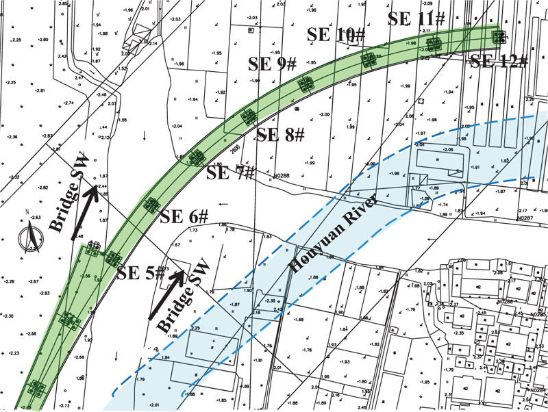
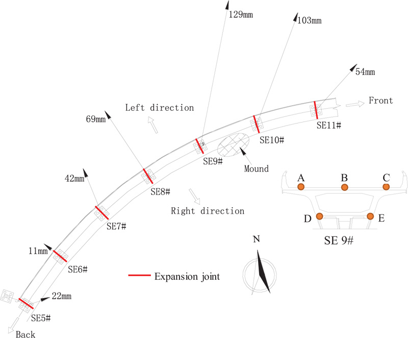
The layout plane of Bridge SE is shown in Fig. (1). As shown in the figure, a prestressed concrete continuous girder with a single box was used as the superstructure of Bridge SE. The construction of this bridge was completed in May of 2010. It was found by inspection and monitoring that all indexes of this bridge were compliant with code specifications until September 20, 2010 [8]. However, several tons of soil have been stacked besides bridge piers for further planting construction since September 21, 2010. Fig. (2) shows the location of the tons of stacked soil. As shown in the figure, the stacked soil was located between two piers, i.e., SE 9# and SE 10#. The mound of soil was as tall as 7.0 m.
1.2. Real-time Measurement Results
The width of expansion joints is measured after finishing the construction of the bridge structure. It was found that the measured widths of several expansion joints, i.e., SE #5, #6, #7, #8, #9, #10, and #11, have exceeded the design value of 120 mm. The detailed measurement results are shown in Table 1, among which the greatest sliding displacement was found for SE #9. The location of Points A-E is shown in Fig. (3). The horizontal displacement of the box girder is presented in Fig. (2) after the tons of soil were piled up. The box girders from SE #7 to #11 moved with different displacements to the left, where SE #9 exhibited the highest displacement of approximately 129 mm.
| Date | Width of Expansion Joint (mm) | ||||
|---|---|---|---|---|---|
| Point A | Point B | Point C | Point D | Point E | |
| September 28th | 168 | 172 | 169 | 170 | 171 |
| October 6th | 186 | 199 | 208 | 193 | 152 |
| October 7th | 189 | 202 | 211 | 196 | 155 |
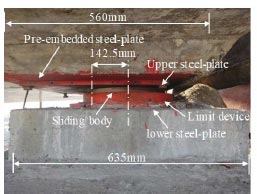
Significant sliding displacements occurred at the bridge bearings of the abovementioned piers. Fig. (3) presents the sliding displacement of the bridge bearing at SE #9 as an example. As shown in the figure, the sliding displacement was as great as 142.5 mm, more than 1/3 of the width of the upper steel plate (440 mm).
Table 2 presents the horizontal displacement and slope rate of all slanted piers at two orthogonal direactions. Noting that the limits of inclination indexes for the bridge piers were 3‰ (slope rate) and 20 mm (top displacement) [9, 10], the inclination of SE #6, #7, #8 and #9 exceeded the limits.
1.3. Finite Difference Modeling
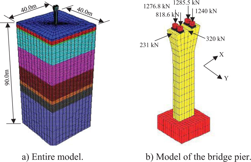
To simulate the mechanical behavior of hidden bridge piles, an FD model, using the commercial software FLAC 3D shown in Fig. (4a), was established by integrating the bridge bearings, pier columns, pile cap, piles, and multiple soil layers. Pile elements were used to simulate the actual bridge piles with a length of 65.0 m. The bridge bearings, pier columns, and pile caps were simulated by solid elements. Concrete C30 and C50 were, respectively, applied for the bridge piles and other bridge members according to the design scheme. The elastic moduli of concrete C30 and C50 were, respectively, 3.00×10¹⁰ MPa and 3.45×10¹⁰ MPa with a uniform Poisson's ratio of 0.20. Goodman's joint element was used to simulate contact behavior between the pile and soil, in which the contact surfaces between the pile cap and soil were defined as sliding contact. The Mohr-Coulomb model was used to simulate the mechanical behavior of soils, whose parameters are shown in Table 3. To improve computation efficiency, the geometrical dimensions of the whole model were selected as 40 m × 40 m × 90 m, as shown in Fig. (5).
| Pier | SE #5 | SE #6 | SE #7 | SE #8 | SE #9 | SE #10 | SE #11 | |
|---|---|---|---|---|---|---|---|---|
| Horizontal displacement (mm) |
Left (+)/ Right (-) |
12 (0.9) | 64 (5.0) | 32 (2.6) | 41 (4.0) | 36 (3.8) | 6 (0.7) | 14 (1.8) |
| Front (+)/ Back (-) |
-3 (-0.3) | -4 (-0.3) | -4 (-0.3) | -4 (-0.4) | -24 (-2.6) | 0 (0.0) | 9 (1.1) | |
| Number | 1 | 2 | 3 | 4 | 5 | 6 | 6 | 8 |
|---|---|---|---|---|---|---|---|---|
| Soil type | Clay | Mud | Mucky clay | Clay | Silty clay | Silty sand | Silty clay | Gravelly sand |
| Thickness (m) | 1.0 | 3.0 | 14.0 | 16.0 | 13.0 | 3.0 | 7.0 | 42.0 |
| Natural gravity (kN/m3) | 18.3 | 16.8 | 17.6 | 19.1 | 18.2 | 20.0 | 19.9 | 20.0 |
| Water rate (%) | 38.6 | 54 | 38.2 | 29.1 | 33.5 | 24.4 | 25.1 | 23.7 |
| Void ratio | 1.104 | 1.56 | 1.029 | 0.868 | 0.868 | — | 0.722 | 0.666 |
| Coefficient of compressibility (MPa-1) |
0.51 | 1.07 | 0.61 | 0.25 | 0.34 | 0.14 | 0.19 | 0.15 |
| Cohesive stress (MPa) | 24.0 | 11.7 | 12.5 | 35.6 | 46.6 | 6.2 | 43.3 | 6.0 |
| Friction angle (°) | 12.4 | 7.9 | 9.5 | 18.4 | 19.3 | 33.6 | 21.2 | 33.8 |
| Poisson’s ratio | 0.35 | 0.42 | 0.39 | 0.35 | 0.30 | 0.22 | 0.36 | 0.20 |
| Shear modulus (MPa) | 1.6 | 0.9 | 1.1 | 2.7 | 3.7 | 5.3 | 3.5 | 4.8 |
| Bulk modulus(MPa) | 4.8 | 8.5 | 4.7 | 8.1 | 8.1 | 7.7 | 11.5 | 6.4 |
| Bearing strength (kPa) | 75 | 45 | 65 | 70 | 180 | 130 | 230 | 280 |
A regional distributed load, whose plane-view dimension was 15.0 m × 8.0 m, was applied on the ground to simulate the action of ground loading. The distribution load was as great as 93.3 kPa, calculated by multiplying the gravity of soil with the average height of 5.3 m. Two-directional horizontal forces of 320 kN and 231 kN were applied on the top of the bridge pier to simulate the action of temperature and creep of concrete, respectively. In addition, four vertical concentrated forces were applied on four bridge bearings to simulate the gravity load of the box girders, as shown in Fig. (4b).
The FD model was calibrated and confirmed by the measurement results of pier displacements. The ultimate calculation results are shown in Table 4, along with the measurement results. As shown in the table, the calculation results fit well with the measurement results.
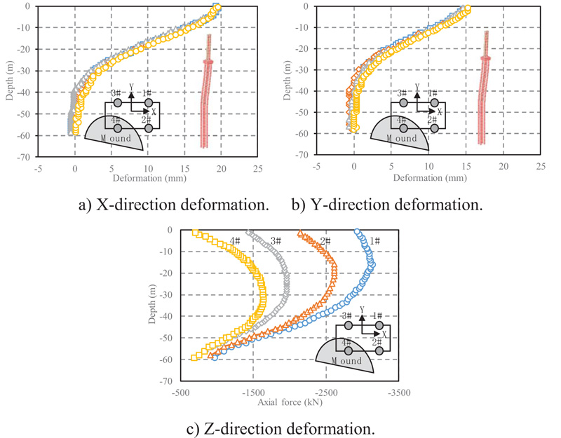
1.4. Calculation Results of Bridge Piles
Fig. (5a, b) show the calculated deformation of four piles under the ground loading. As shown in the figure, the maximum deformation of these piles in the X and Y directions was 19.4 mm and 15.2 mm, respectively. The maximum bending moments in the X and Y directions were 1432 kN·m and 1548 kN·m, respectively. As the designed bending capacity of these four piles was as great as 1851.2 kN·m, the bending performances of these four piles were within the safe state. Fig. (5c) shows calculated results of axial force distribution of these four piles along the pile length. As shown in the figure, the maximum axial forces among these four piles were 3110 kN, much smaller than the designed capacity of 6481 kN.
The calculation results indicate that the ground loading was the major reason inducing the inclination of the bridge. Under the unbalanced ground loading, four bridge piles sustained different axial forces and two-direction bending moments, inducing uneven deformation of the bridge piles. Connected rigidly to the bridge piles, the bridge piers deformed in coordination with the bridge piles, inducing an abnormal situation for the bridge bearings and expansion joints. In addition, the piles and connected bridge piers were within the elastic state and did not have to be strengthened.
| Number of Measurement Points | X-direction Displacement (mm) |
Y-direction Displacement (mm) |
Total Displacement | |||||
|---|---|---|---|---|---|---|---|---|
| Measurement | Calculation | Measurement | Calculation | Measurement | Calculation | |||
| 1 | / | 37.6 (Average value) |
35.0 | / | -56.3 (Average value) |
52.7 | 67.7 (Average value) |
63.3 |
| 2 | 40.0 | -49.0 | ||||||
| 3 | 41.0 | -59.0 | ||||||
| 4 | 32.0 | -61.0 | ||||||
2. MATERIALS AND METHODS
2.1. General Construction Procedure
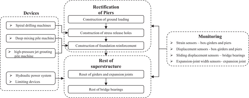
Fig. (6) presents a construction flow chart of the general strengthening scheme. The main construction programs were executed according to the following steps.
1. Sensors were first installed at specific positions to monitor strains and displacements of the box girders and piers, sliding displacement of the bridge bearings, the width of the expansion joints, and ground displacements.
2. Limiting devices were installed at the bridge bearings to prevent the movement of girders during the rectification of bridge piers. A hydraulic power system was simultaneously installed at the bridge bearings to reset the bridge piers, girders, and bearings.
3. Initial values of the installed sensors were measured as a reference for subsequent monitoring.
4. Slanted piers were rectified in three steps: 1) construction of a reverse ground loading; 2) construction of stress release holes; and 3) construction of a foundation reinforcement.
5. Recovery of the abovementioned members was conducted in two steps: 1) the bridge piers, girders, and expansion joints were reset, and 2) the damaged bridge bearings were replaced.
a) Entire model. b) Model of the bridge pier.
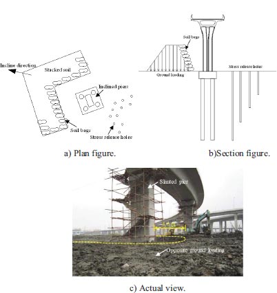
2.2. Construction of Reverse Ground Loading
The stacked soils were removed immediately once the bridge abnormalities were detected. Then, reverse ground loading was conducted by stacking soil at the opposite side of SE #6, SE #7, SE #8, and SE #9 to produce a reverse incline of bridge piers. Fig. (7) shows schematic and actual views of the reverse ground loading. As shown in the figure, the distance between the toe of the mound and the edge of the piers was 4.0 m. The mound was 10.0 m wide with 13 layers. The first soil layer was 4.0 m high. Soil layers were subsequently added, each of which was 0.5 m high. A new layer was only added when the speed of deep displacement was no more than 2.0 mm/d. The total final soil weight was 38200 kN.
2.3. Construction of Stress Release Holes
Several rows of stress release holes were constructed on the opposite side of the reverse ground loading to shorten the procedure of the reverse incline of bridge piers. Stress release holes with diameters of 120-150 mm were dug using spiral drilling machines. As shown in Fig. (7), these holes were arranged in three or four sector-shaped rows with a spacing of 0.5-1.0 m. The design distance between the edge of the piers and the nearest hole was 2.0 m. The stress release holes in different rows had different depths. The stress release holes with the largest depth (20.0 m) were in the nearest row to the pier. The depth of the stress release holes was reduced by 5.0 m for each subsequent row. Pipes were embedded in the holes as a preparation for grouting with cement paste to prevent excessive ground deformation. After the pier rectification, all holes were filled with cement paste to prevent ground instability.
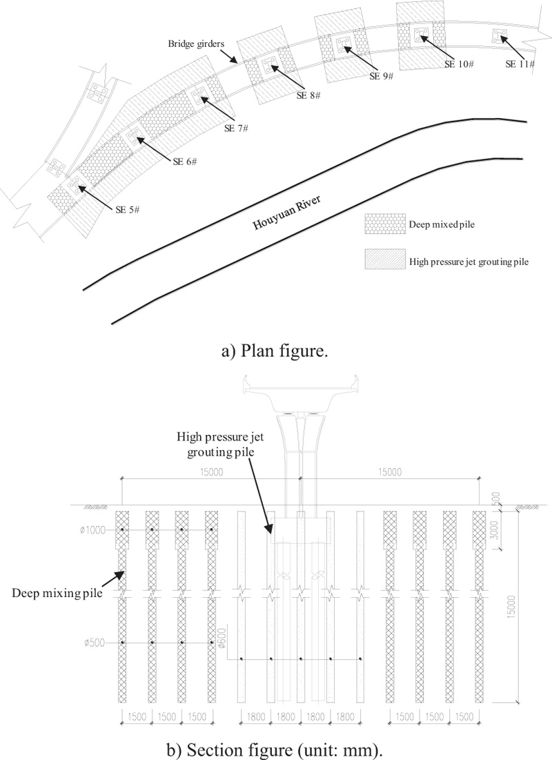
2.4. Construction of Ground Reinforcement
Fig. (1) shows that the bridge is close to the Houyuan River. Two types of piles were constructed around the bridge piers as ground reinforcements to stabilize the foundation and prevent riverbank landslides. The first type was a deep-mixed pile, and the second type was a high-pressure jet grouting pile. Fig. (8a, b) show the plane and section for the two types of piles. The high-pressure jet grouting piles were used because the height of the machinery used to construct low-cost deep-mixed piles exceeded that of the girder-covered area. With the longitudinal axles of bridge piers as the axis of symmetry, the total width of the ground reinforcement area was 30.0 m. The ground adjacent to SE #10 and SE #5 was also reinforced to prevent potential soil deformation induced by the reverse ground loading.
As shown in Fig. (8b), the side profile of deep-mixed piles was applied as a nail shape. Arranged in rectangular arrays of 1.5-m spacing, the total length of these piles was 15.0m with an expanded 3.0-m-long top. The diameters of the expanded and other segments were 1000 mm and 500 mm, respectively. The piles were 15% cement, and the design's unconfined compressive strength on the 28th day was no less than 750 kPa. The high-pressure jet grouting piles had similar lengths with a diameter of 600 mm. The piles were arranged in rectangular arrays with a 1.8-m spacing. The edge area of the high-pressure jet grouting pile was placed 2.0 m away from the edge of the pile cape to prevent damage to the bridge piles against the high injection pressure of 20 MPa.
2.5. Reset of Bridge Piers, Girders and Expansion Joints
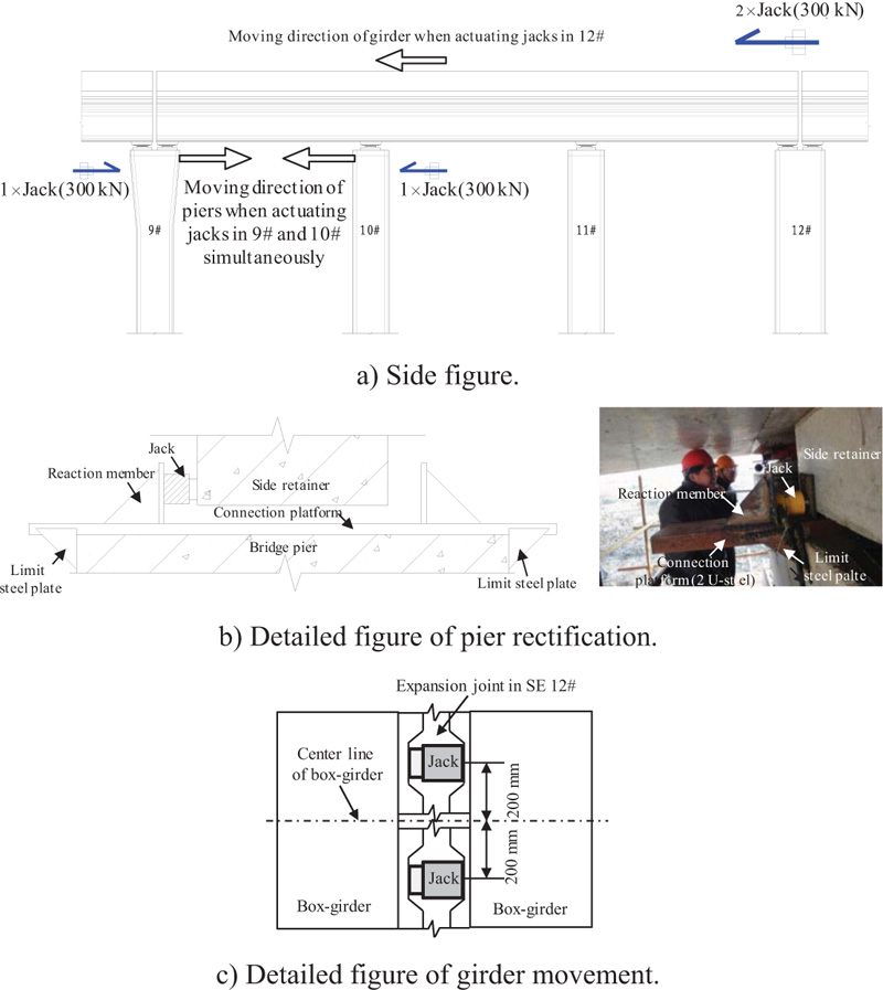
A hydraulic power system using jacks was introduced to rectify two of the most slanted bridge piers, SE #9 and #10. Fig. (9) shows the structure of the hydraulic power system using jacks. As shown in Fig. (9a), two 300-kN jacks were installed at SE 9# and SE10#, and a pair of pushing forces was acted on top of these two bridge piers by reaction forces from the girder structure. The reaction forces were transmitted by the limiting structure and the side retainer of the bridge girder. The limiting structure was preassembled on top of the bridge piers and composed of three members: 1) a reaction member; 2) a limiting steel plate; and 3) a connection steel plate.
A similar hydraulic power system was used to push the shifted girder back to its original position, restoring the expansion joints to their original width. Taking the expansion joint of SE #12 as an example, two 300-kN jacks were simultaneously installed at the expansion joint of SE #12 with a 400 mm spacing. Supported by the girder between SE #12 and #15, a horizontal pushing force was applied to the girder between SE #9 and #12. Real-time monitoring results were used to adjust the pushing force and switch the next pushing case. The target displacement of each pushing case was applied as 5.0 mm, and the design interval of the construction period was 5 days.
2.6. Replacement of Damaged Bridge Bearings
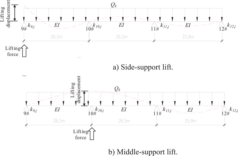
Some bridge bearings required being replaced because of the non-code-compliant deformation of the bolts and the upper steel plates. To provide essential space for replacement of damaged bridge bearing, a hydraulic system was used to lift the girder temporarily. Lifting forces were calculated by a simplified calculation model, which is shown in Fig. (10). As shown in the figure, the dead loads (line load, Qk), the flexural rigidity (EI) of the girders, and the stiffness of bridge bearings (ki,j, where i indicates the number of piers, and j indicates the transverse location, with 1=left and 2=right) were taken into account in the calculation model. In the calculation model, fourd bridge piers were simulated by articulated hinged supports. The calculated lifting force of bridge bearings is shown in Table 5.
| Pier | Transverse position | Lift force (kN) | Total lift force (kN) |
|---|---|---|---|
| #9 | Left | 1374 | 2224 |
| Right | 850 | ||
| #10 | Left | 2868 | 4143 |
| Right | 1275 | ||
| #11 | Left | 2749 | 4218 |
| Right | 1469 | ||
| #12 | Left | 1333 | 2119 |
| Right | 786 |
| Period | Direction | #6 | #7 | #8 | #9 |
|---|---|---|---|---|---|
| Before rectification | Longitudinal | -0.3 (0.02) | -1.1 (0.07) | -22.1 (0.15) | -35.3 (2.71) |
| Transverse | -19.8 (1.07) | 15.2 (0.10) | 8.3 (0.06) | -28.1 (2.16) | |
| After rectification | Longitudinal | 3 (0.16) | -0.8 (0.01) | 10.2 (0.07) | -7.9 (0.61) |
| Transverse | 4.2 (0.23) | 8.9 (0.06) | 14.4 (0.10) | -7.8 (0.30) |
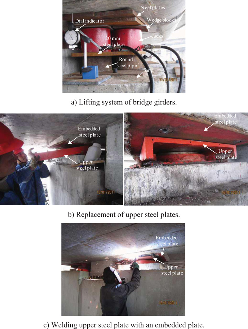
Fig. (11a) shows the lifting system using jacks along with the added members and dial indicators. A bottom steel plate supported by sand was used as a platform. Round steel pipes were used to eliminate the difference between the maximum stroke of the jacks and the headroom under the girder. Steel plates with a 20-mm thickness were inserted between the jacks and the steel pipes to improve the stability of the lifting system. Wedge blocks were placed on top of the jacks with a slope rate of 5% to accommodate the bottom surface of the girder. Steel plates were inserted between the jacks and the girder to prevent local compression failure of concrete.
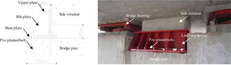
The damaged upper steel plate and bolts were removed after lifting bridge girders by 3-5 mm, as shown in Fig. (11b, c). A new upper steel plate was added to replace the damaged upper steel plate and welded to the embedded steel plates. Limiting devices were installed in advance to prevent longitudinal girder motion. Fig. (12) shows the detailed structure of the limiting devices. The limiting devices were placed in front of the side retainer and bolted to the bars plated into the girder in advance.
The damaged upper steel plate and bolts were removed after lifting the bridge girders by 3-5 mm, as shown in Fig. (11b, c). A new upper steel plate was added to replace the damaged upper steel plate and welded to the embedded steel plates. Limiting devices were installed in advance to prevent longitudinal girder motion. Fig. (12) shows the detailed structure of the limiting devices. The limiting devices were placed in front of the side retainer and bolted to the bars plated into the girder in advance.
3. RESULTS AND DISCUSSION
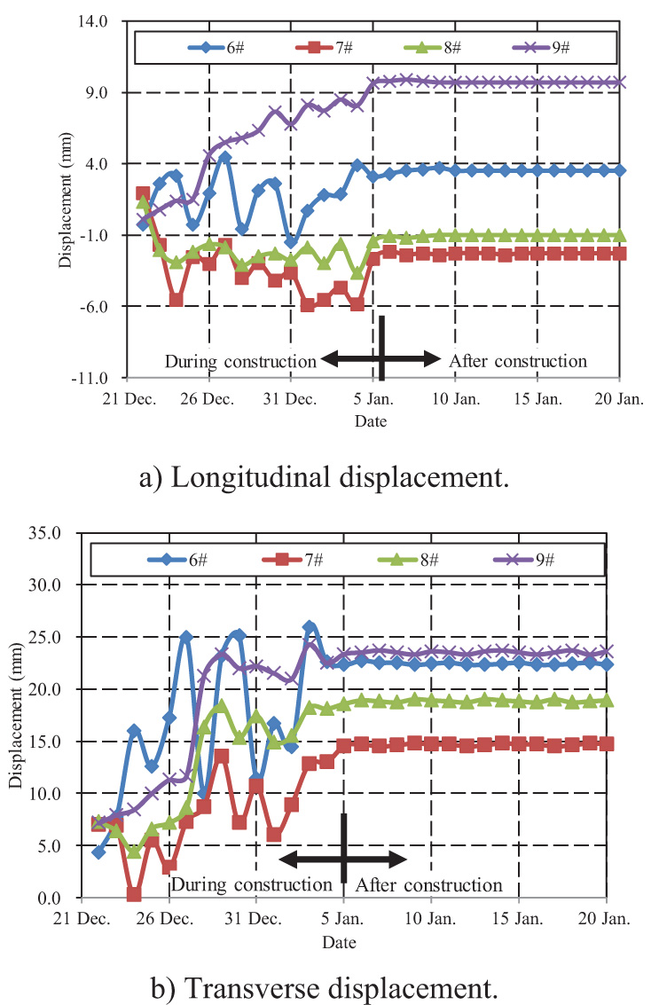
An overall laser meter was used to monitor the displacement of bridge piers. Fig. (13) presents monitoring curves of pier-top displacement during and after pier rectification construction. As shown in the figure, the transverse pier-top displacement was much higher than the corresponding longitudinal displacement. The displacement of the piers continued to develop after terminating the reverse ground loading but did not change after completing construction. It indicated that the ground reinforcement could sufficiently prevent creep deformation of soft soils. Table 6 shows measured results of pier displacements before and after rectification of bridge piers. As shown in the table, the slope rate and the top pier displacement decreased within the permitted scope in both directions.
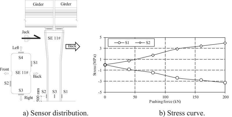
Strain measurements were carried out for SE #11 during the construction. Fig. (14a) shows the installed location of four strain sensors. As shown in the figure, these four sensors, labeled as S1, S2, S3 and S4, respectively, were installed on four sides of the monitored bridge piers in a uniform cross-section of 500 mm above the ground.
Fig. (14b) shows stress curves of S1 and S2 multiplied by the elastic modulus of C50 concrete (3.45×10⁴ MPa) for a pushing force ranging from 0 kN to 200 kN [11]. As shown in the figure, a tensile stress of 3.96 MPa was induced by the pushing force. In addition, the compressive stress of the cross-section was -3.00 MPa, but the maximum actual tensile stress under the maximum pushing force was only 0.96 MPa, which was much less than the tensile strength of concrete C50 (1.89 MPa).
CONCLUSION
The evaluation, rectification, and specifications of a slanted continuous concrete box-girder bridge located in a soft-soil area in China are presented in this paper. The following conclusions are drawn from the evaluation, design, construction and monitoring results for this project.
1. The proposed method integrating reverse ground loading and a jack-involved pushing system can successfully rectify the bridge induced by the uneven ground settlement. Arrangement of the stress release holes can help shorten the construction period of the rectification. The ground reinforcement is essential to prevent great creep displacement of the soft soil, which may induce secondary rectification. The success of this project presents that positive and passive measures can both rectify slanted structures by forcing structural displaces of superstructures and foundations. Selection or combination of different rectification measures depends on both geotechnical conditions and the robustness of structures. For soil sensitive to deformation, passive methods, such as drilling stress-releasing holes, should be carefully adopted to prevent irreversible tilting or excessive rectification.
2. The jack-involved hydraulic power technique is useful to replace and repair damaged bridge bearings. The supposed lifting structure has been proved to be safe and convenient for extending the stroke of small jacks. As the connection between components has to be canceled or weakened, it is crucial to prevent overall instability or slippage of the structure during construction of lifting or forced rectification. Therefore, limiting devices are also essential to prevent the falling of the lifted girders.
3. Real-time monitoring of soil and pier displacement can provide useful information for actual control of ground loading, stress release holes and pushing force of jacks. By means of strain monitoring, the stress is controlled under the elastic range of concrete. No visible cracks were observed on the surface of the bridge piers and girders.
CONSENT FOR PUBLICATION
Not applicable.
AVAILABILITY OF DATA AND MATERIALS
The data and supportive information are available within the article.
FUNDING
The study has been supported by Foundation Research Project of Jiangsu Province, the Natural Science Fund No. BK20211003 and “Six Talent Peaks” High-level Talent Project of Jiangsu Province No. jz-062.
CONFLICT OF INTEREST
The authors declare no conflict of interest, financial or otherwise.
ACKNOWLEDGEMENTS
Declared none.

