All published articles of this journal are available on ScienceDirect.

Stability Charts for Limiting Horizontal Normal Pressure on Cohesive-frictional Backfill for Deep Contiguous Piled Walls
Authors Info & Affiliations
Abstract
Background:
This study presents a numerical solution for determining the limiting uniform normal pressure acting horizontally behind cohesive-frictional backfill material in a deep contiguous piled wall. At this limiting pressure, the soil tends to flow out in gaps between a series of vertical piles placed at a certain uniform horizontal spacing.
Methods:
The lower and upper bound plane strain finite element limit analysis (FELA) has been carried out for this purpose. The Mohr-Coulomb failure criterion, using an associated flow rule, was employed to impose the yield condition in the soil mass.
Results:
A parametric study was carried out to obtain the magnitude of the non-dimensional limiting lateral resistance (F/cD) as a function of normalized pile spacing (S/D), the friction angle of soils (ϕ), and the adhesion factor (δ) at the soil-pile interface; here, F refers to the lateral normal resistance (force) per unit length offered by the pile, S forms the clear spacing between piles, D is the diameter of the pile and c is soil cohesion. The impact of the different parameters on the failure mechanisms has been examined comprehensively.
Conclusion:
The lateral resistance (F/cD) offered by the piles increases generally with a decrease in the spacing between the piles. The magnitude of F/cD increases further with an increase in the values of ϕ and δ.
1. INTRODUTION
Deep foundations’ excavations of high-rise structures or tube stations have become increasingly popular in metropolitan areas. Such excavations in weak clay are commonly done by employing steel sheet pile walls and concrete diaphragm walls. A contiguous piled wall, a type of retaining wall system, creates a very useful option for supporting deep excavations (North-Lewis and Lyons [1], Moh and Chin [2], Gaba et al. [3], Ou [4], Huynh et al. [5], Teparaksa [6], and Zhang et al. [7]). The contiguous piled wall is usually made up of a series of cast in-situ vertical piles with a narrow gap having soil in between,which has only marginal shear strength. In the case of stiff clayey backfill material, the clear spacing between adjacent piles can be made equal to or even greater than the pile diameter (Clayton et al. [8]). For permanent or temporary constructions, including deep basements, underpasses, shaft stations of tunnels, and cut-and-cover tunnels, huge and narrow diameter drilled cast-in-place piles, with or without facing elements, are commonly employed to form a contiguous piled wall system. More information about the construction of such a piled wall system to support deep excavations can be found in reported studies [9, 10].
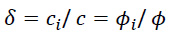
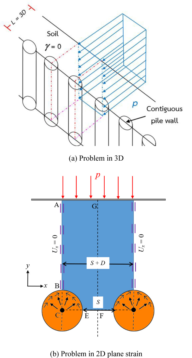
The spacing between neighboring piles, in relation to pile’s diameter, forms an important parameter which affects the stability of a contiguous piled wall. Despite the fact that soil gaps in neighboring pile walls are generally visible, the soil media remain, however, generally stable due to stabilization process caused by a soil arching effect which occurs in soil gaps between two adjacent piles with lateral earth pressure acting from behind. The essential component of this design challenge remains the prediction of the limiting horizontal normal earth pressure behind soil gaps, as well as the limiting lateral (horizontal) resisting force offered by an individual pile in such a contiguous piled wall. The problem of the limiting pressure behind soil gaps in a contiguous piled wall in cohesive-frictional soil is depicted in Fig. (1a). Fig. (1b) indicates the top (plan) view and the piles have been marked as circles. It is assumed that piles are very long as compared to their diameter and there is no normal strain in the direction of piles, and the plane strain condition will accordingly remain applicable for the two-dimensional problem indicated in Fig. (1b). A row of evenly spaced stiff circular piles with a diameter of D creates soil gaps with a clear distance of S. Each column pile is considered to have continuous bracing, causing it to act like a rigid and fixed structure that cannot move. A lateral earth pressure behind soil gaps (p) produces a widespread collapse in soil media. A cohesive-frictional soil, with cohesion (c) and friction angle (ϕ), is assumed to behave as a perfectly plastic material obeying the Mohr-Coulomb yield criterion with an associated flow rule; the soil mass is assumed to be a weightless medium. This study takes into account the adhesion factor (δ) along the soil-pile interface, which is defined as follows:
 |
(1) |
where ci = cohesion at the soil-pile interface
c = cohesion of surrounding soil
ϕi = friction angle along the soil-pile interface
ϕ = friction angle of surrounding soil
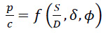
The adhesion factor (δ) for the soil-pile interface was assumed to be 0, 1/3, 1/2, 2/3, and 1. It is to determine the uniform limiting normal pressure (p) acting horizontally on the vertical face of the backfill material, which causes a failure in soil gaps of a contiguous piled wall. The magnitude of p can be described in terms of the following dimensionless parameters:
 |
(2) |
where p/c = the limiting normalized pressure behind soil gaps
S/D = clear spacing to diameter ratio of the piles
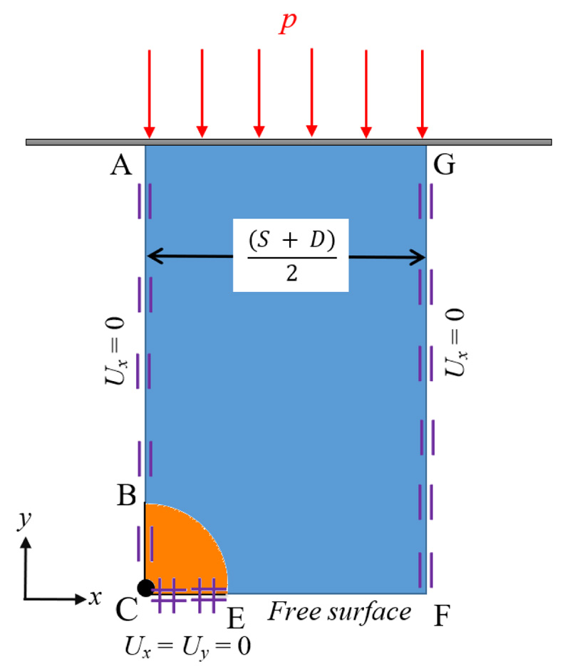
The force equilibrium direction along the direction of p can be used to compute the limiting lateral horizontal force (F) acting on an individual pile per unit height of the contiguous wall using a free body diagram as indicated in Fig. (2). Thus, a suitable inter-relationship between F and p may be expressed in terms of dimensionless parameters by considering a free body diagram of one pile with half of the soil gaps in each side of the pile as follows:
 |
(3) |
where F/cD= lateral force factor acting on a single pile per unit height of the contiguous piled wall.
The soil arching effect phenomenon identified in this problem can be compared with the active trapdoor problem [11]. Numerous researches on the stability of active trapdoors have been undertaken utilizing analytical and experimental analyses, including the method of stress characteristics [12, 13], lower and upper bound solutions [14], the finite element analysis [15], and the finite element limit analysis [16-20]. The published approaches for an undrained active trapdoor, on the other hand, cannot be immediately adapted to the contiguous piled wall problem due to major differences in the boundary conditions of the two problems. In addition, the problem of a deep contiguous piled wall comprises multiple soil gaps, unlike the problem of a trapdoor which has only a single soil gap.
There were numerous attempts to examine the arching effect in soils [21-29], but no plasticity solution for computing the normal earth pressure behind soil gaps in a contiguous piled wall in cohesive-frictional soil with the consideration of the pile-soil adhesion factor has yet been addressed. In the existing investigations [21, 26, 29], only limited information is available to determine the magnitude of the ultimate lateral pile force factor F/cD for cohesive-frictional soils. Ito and Matsui [21] investigated the arching effect between a row of stabilizing rigid piles and used the limit equilibrium approach with a proposed failure mechanism to determine the lateral force acting on a pile per unit length. Matsui et al. [26] also used a failure mechanism similar to that of Ito and Matsui [21] to study the problem of a contiguous piled wall. Ukritchon and Keawsawasvong [29] carried out the finite element limit analysis (FELA) to study the same problem in cohesive-frictional soils. It should be mentioned that these studies [21, 26, 29] did not consider thoroughly the effect of pile-soil adhesion factors on the results. Haema and Tanseng [25] studied the collapse process of soil gaps behind contiguous piled walls under undrained conditions using physical models and high-quality block clay samples. In the present study, by using the rigorous finite element limit analysis, the full range of adhesion factors has been considered for solving the problem of a contiguous piled wall.
By using the finite element limit analysis (FELA) commercial code, namely OptumG2 [30], the present study proposed novel plasticity solutions for finding the limiting earth pressure factor (p/c) behind soil gaps and the limiting pile resistance force factor (F/cD) operating on a pile per unit height of the contiguous piled wall. The parametric analyses of the pile spacing to diameter ratio (S/D), friction angle (ϕ), and adhesion factor (δ) along the pile-soil interface are undertaken, encompassing S/D = 0.1 to 3.0, ϕ = 0 to 40°, and δ = 0 (smooth) to 1 (rough) in order to predict the values of p/c and F/cD for a contiguous piled wall in practice. It should be mentioned that the present study considers the problem of a deep contiguous piled wall in cohesive-frictional soils with several combinations of S/D, ϕ, and δ.
2. METHOD OF ANALYSIS
Following the contribution from Sloan [21], the FELA has become a very important tool for assessing many complicated geotechnical stability problems [31-42]. The plastic bound theorem is used to bracket precisely the limit load by upper and lower bound solutions, combining the tremendous capabilities of finite element discretization for managing intricate soil stratifications, loadings, and boundary conditions. The fundamental bound theorems are based on the assumption of a completely plastic material with an associated flow rule. Both lower and upper bound problems, under plane strain case, are solved as the second-order cone programming (SOCP) in OptumG2 [30].
Fig. (2) shows a numerical model of the problem of determining the limiting normal earth pressure behind soil gap under plane strain conditions. The model, which uses only a fourth of the rigid circular piles and half of the soil gaps, is fully prepared using symmetrical circumstances. In both upper and lower bound computations, the soil and pile domains are discretized into a series of triangular elements. A rigid element is assumed to model the pile material without any movements. The circumferential length of the soil-pile interface is described as interface elements, allowing for velocity and stress discontinuities in upper and lower bound computations, respectively. On account of symmetry, the model's left and right boundaries are locked horizontally. A free surface forms the bottom border of the soil gap. Each column pile's horizontal centerline border is fixed in both directions to ensure that the rigid pile does not displace. At the top boundary of the model, a uniform surcharge pressure, p, is imposed and adjusted in both upper and lower bound computations. The failure zone does not touch the top (side) boundary due to the adequate length (length GF in Fig. (2)) of the chosen domain; therefore, the computed limit loads remain unaffected if the length GF is increased. An automatic mesh adaptivity procedure was adapted to develop very accurate upper and lower bound solutions for the limiting pressure behind the soil gap, as illustrated in Fig. (3). Following initial calibration tests, five rounds of adaptive meshing with the number of elements rising from 5,000 to 10,000 were utilized for all the studies. The sizes of the elements were gradually reduced towards/around the region of plastic failure.
3. RESULTS AND COMPARISONS
3.1. Comparison with other Studies
A comparison of F/cD between the present study and the existing solutions by Keawsawasvong and Ukritchon [27] (FELA) and Haema and Tanseng [25] (physical models) is shown in Fig. (4). Noted that the solutions by Keawsawasvong and Ukritchon [27] are the average of the UB and LB results obtained on the basis of the FELA. The results shown in Fig. (4) are meant for purely cohesive soils (ϕ = 0°) for both rough (δ = 1) and smooth (δ = 0) interfaces. It can be seen that the average FELA solutions match very well with the present results for both rough and smooth interfaces. Note that the magnitude of F/SUD for δ = 1 becomes greater than that for δ = 0; here Su implies the undrained shear resistance, Su = c for a purely cohesive soil.
3.2. Main Findings of the Present Study
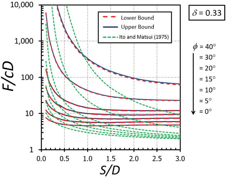
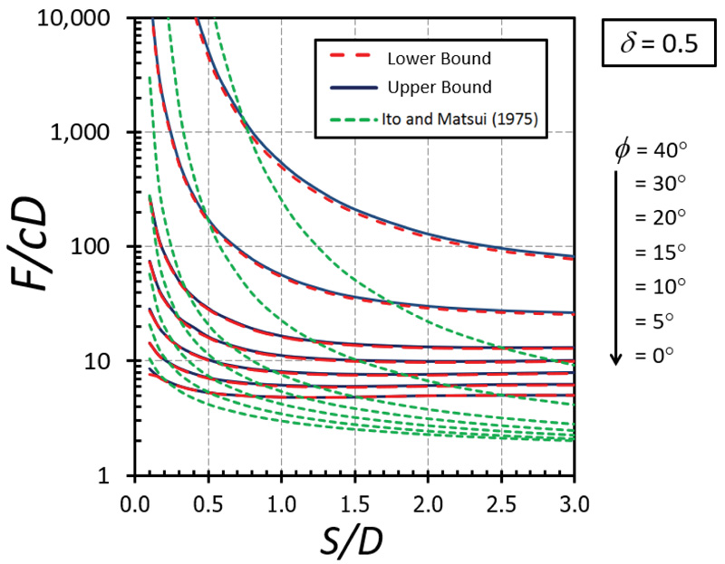
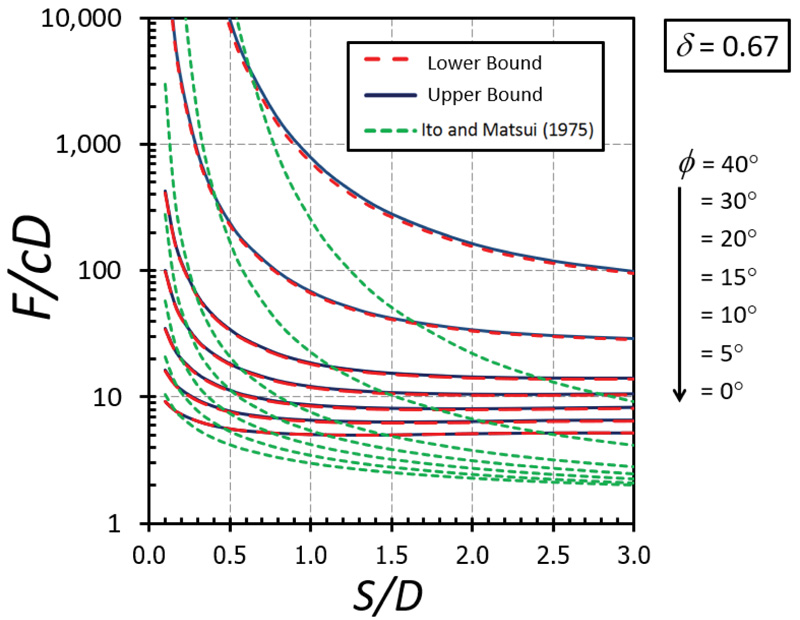
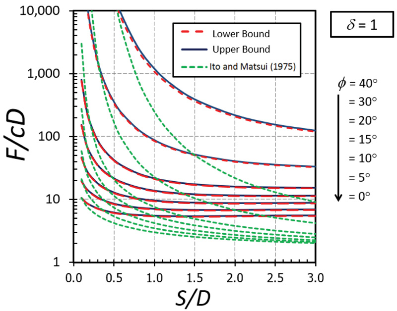
The nonlinear relationships between F/cD and S/D are depicted in Figs. (5-9) for the cases of δ = 0 (fully smooth), 1/3, 1/2, 2/3, and 1(fully rough), respectively. The different curves in these figures correspond to the values of ϕ between 0 and 40°. Note that the value of the F/cD can be accurately bracketed by computed upper (UB) and lower (LB) bound solutions within 3% for all cases. Generally, the magnitude of F/cD reduces dramatically when S/D increases and remains constant thereafter when S/D becomes larger than 2. For a narrow soil gap, S/D = 0.1, the arching effect generates very high values of the F/cD. The solutions of F/cD between the present study and the Ito and Matusi study [21] are also compared in Figs. (5-9) for all cases of the adhesion factor δ. Ito and Matusi [21] used the limit equilibrium method with an assumption of the failure mechanism to predict the solutions based on the force equilibrium. However, their method did not consider the influence of the adhesion factor since the method is developed from the equilibrium of forces acting on the cross-section of piled walls. It is found that the solution provided by Ito and Matusi [21] differs significantly from that obtained from the present analysis; both the solutions, however, generate a similar trend about the effect S/D on F/cD. The solutions obtained from the present study do not involve any assumption about the geometry of the failure surface and, therefore, will provide much more accurate answers. The design charts developed in Figs. (5-9) will be useful for obtaining the limiting lateral pile force factor F/cD for a contiguous piled walls in cohesive-frictional soils which can be employed in practice.
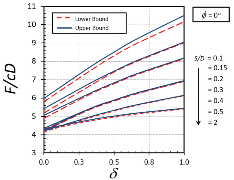
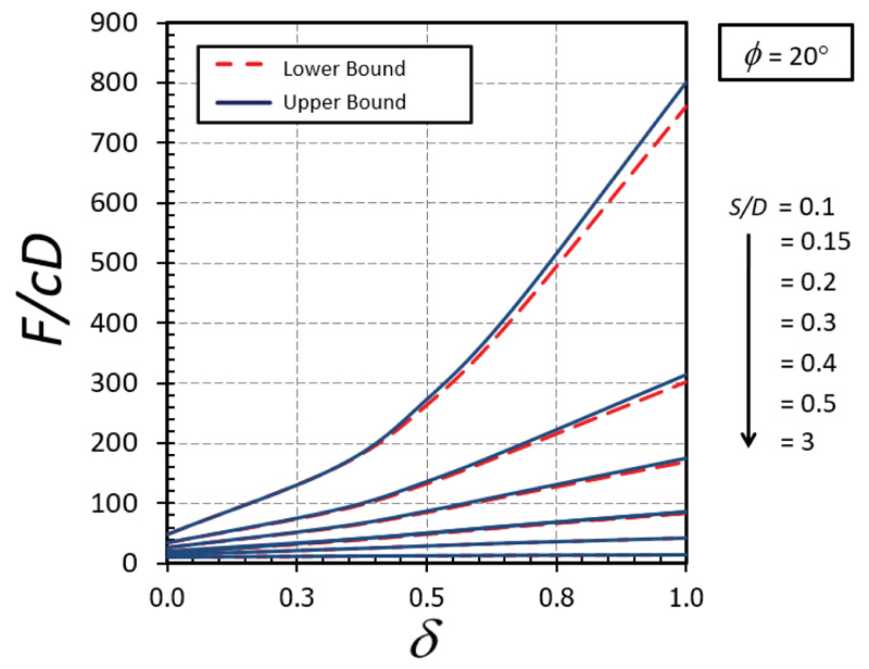
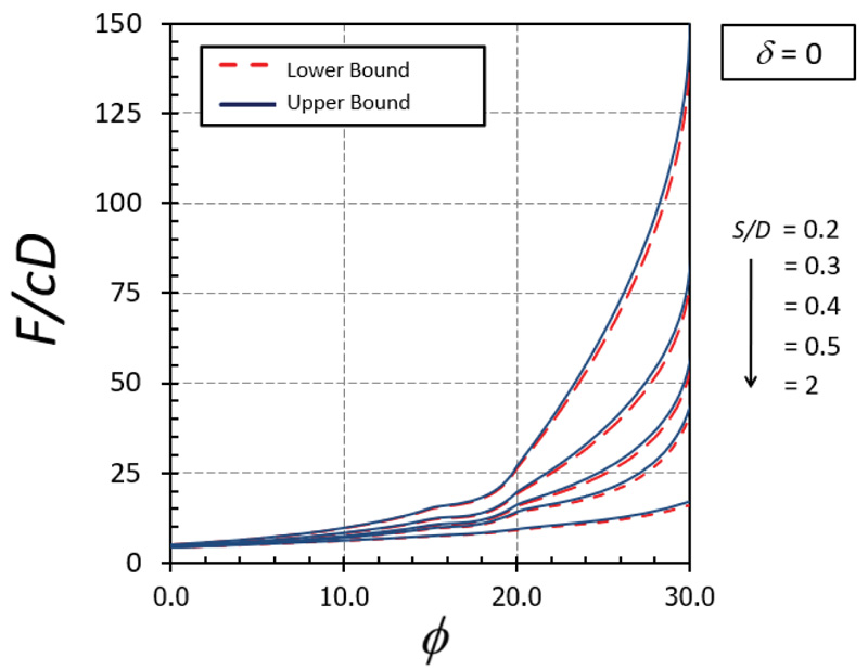
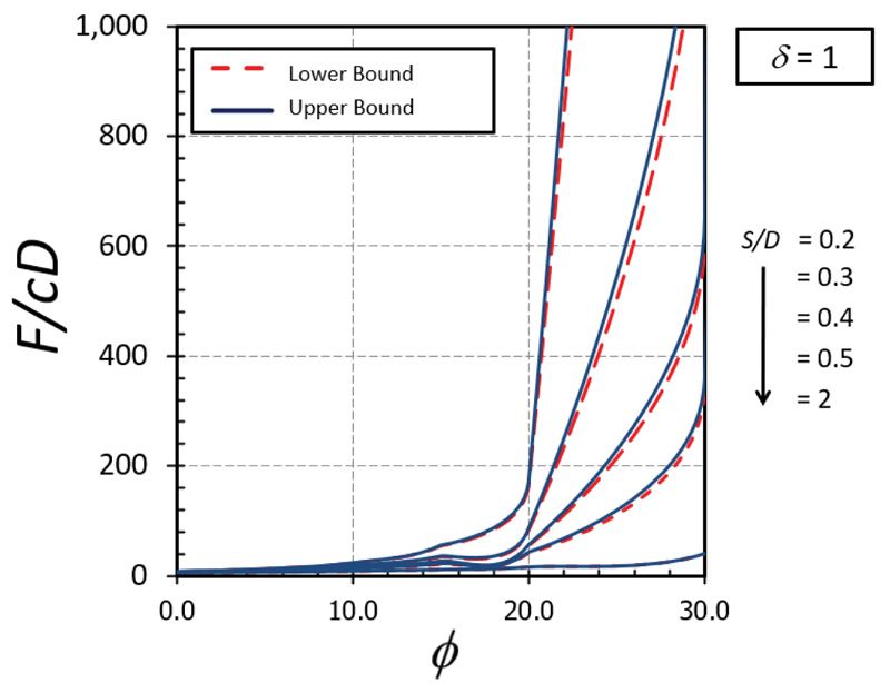
The influence of δ on F/cD is shown in Figs. (10-11) for the cases of ϕ = 0° and 20°, respectively. A nonlinear relationship between δ on F/cD can be found in both cases. It can be seen that the effect of δ becomes significant in determining the magnitude of F/cD when the soil gap is very narrow (that is, S/D = 0.1). Also, the curves of the cases with a small value of ϕ are convex (Fig. 10) while those with a large value of ϕ are concave (Fig. 11). The impact of ϕ on F/cD is depicted in Figs. (12-13) for the cases of δ = 0 and 1, respectively. Clearly, the effect of ϕ on the results becomes very significant when the value of ϕ becomes greater than 20°.
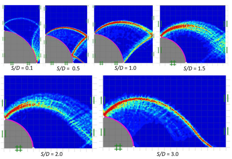
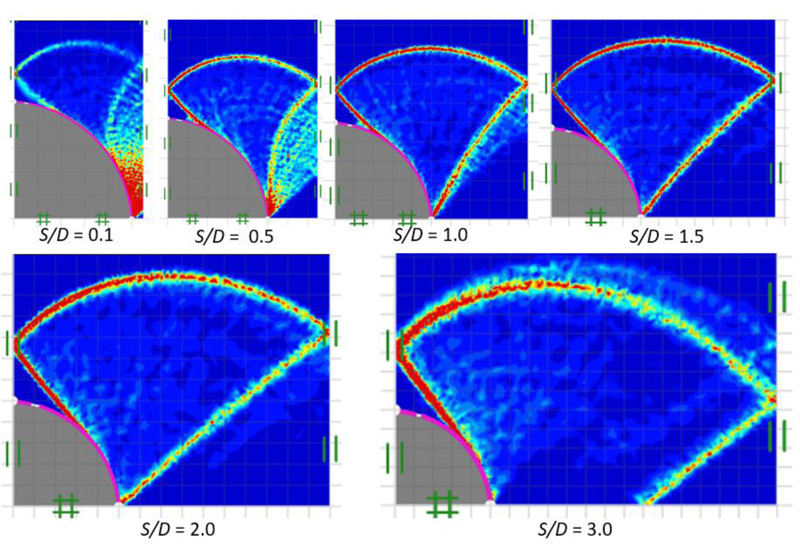
3.3. Failure Mechanisms
Figs. (14 and 15) show failure patterns which were drawn showing the variation of the power dissipation function from a narrow to a wide soil gap for smooth and rough piles (that is, δ = 0 and 1), respectively, as well as soil friction angle of ϕ = 15° with varying soil gap ratios, S/D = 0.1-3.0. In Fig. (14), a radial shear zone behind the soil gap is substantially confined between stiff piles for a narrow soil gap (S/D = 0.1). A stiff curvilinear triangle zone can be seen behind the soil gap for S/D = 0.5-1.0, which results from an increase in the size of the radial shear zone. Shear bands spread entirely across the free surface of the soil gap as the soil gap becomes wider S/D > 1.0. It is shown in Fig. (15), in the case of a rough pile-soil surface (δ = 1) with the same selected range of parameters, as the soil gap ratio increases, the radial shear zone behind the soil gap also increases and spreads wider, generating a curvilinear triangular arching path.
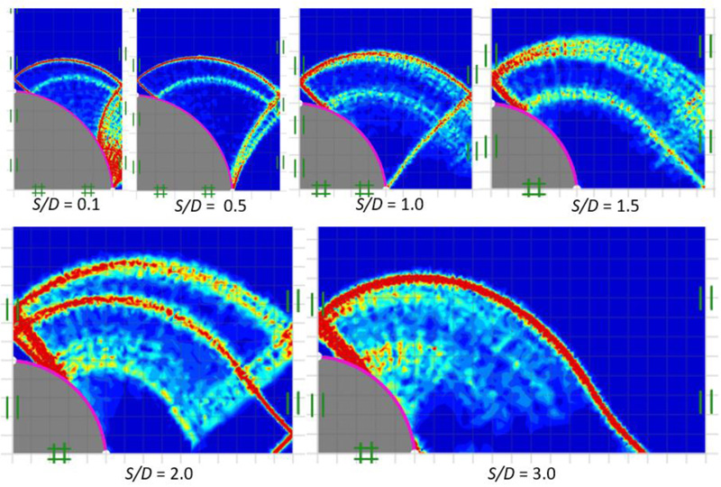
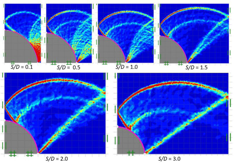
The comparisons of power dissipation function in soil gap with δ = 0.67 for ϕ = 0° and 30° are shown in Figs. (16 and 17), respectively. In the case of ϕ = 0°, for S/D = 0.1-1.0, the arching effect is represented by the direction of the major principal stress, which produces an arch-shaped route that transmits to contact the soil gap's centerline. On the other hand, as the pile diameter to spacing ratio increases, the arching path spreads further and shifts outward from the soil gaps centerline, as shown in Fig. (16). For ϕ = 30°, the arching path develops as the soil gap increases. The curvilinear triangular zone is observed in all failure patterns for all ranges of S/D. As can be observed in Fig. (17), the failure mechanism, in this case, appears to be a fan shape that shifts from the problem centerline and then terminates at the pile interfaces.
4. DISCUSSION
The present study attempts to determine the stability of a deep contiguous piled wall based on a simple two-dimensional plane strain formulation. From the analysis, one can determine the maximum value of the uniform earth pressure (p) in the in-situ soil mass, which can be exerted on such a cohesive frictional backfill material supported by a series of deep vertical piles. Based on a simple active earth pressure theory, one can determine an equivalent value of uniform lateral earth pressure. If this value of the active earth pressure becomes greater than the limiting value of supporting pressure (determined from the present solution), the contiguous piled wall will remain stable, otherwise, it will simply lead to failure. As such, the piles will be supported only at the bottom, not along their lengths, as assumed in the present analysis in order to determine a solution simply using a plane strain formulation. The two dimensional analysis is rigorous in nature, however, the conversion from three-dimensional formulation to two-dimensional formulation involves some approximations, which will form the limitation(s) of the current analysis.
CONCLUSION
On the basis of the rigorous plane strain finite element limit analysis, the lower and upper bound solutions for evaluating the limiting horizontal normal earth pressure behind cohesive-frictional backfill material in a deep contiguous piled wall have been established. These obtained solutions will be applicable for the cases when the length of the pile remains much greater (longer) as compared to its diameter. Failure mechanisms have also been examined thoroughly in all the cases. The obtained solutions were validated by making comparisons with the results reported in the literature. All the results were provided in the form of non-dimensional charts, which will be useful for design purposes. The lateral resistance (F/cD) offered by the piles increases generally with a decrease in the spacing between the piles, and it increases further with an increase in the values of ϕ and δ. Note that the present problem is modeled by using a two-dimensional plane strain formulation. The possible future work for this problem will be obtaining the solution using a three-dimensional formulation for a more realistic simulation.
LIST OF ABBREVIATIONS
| FELA | = Finite Element Limit Analysis |
| SOCP | = Second-Order Cone Programming |
CONSENT FOR PUBLICATION
Not applicable.
AVAILABILITY OF DATA AND MATERIALS
The data that support the findings of this study are available on request from the corresponding author [J.K].
FUNDING
This study was supported by Bualuang ASEAN Chair Professor Fund by Thammasat University.
CONFLICT OF INTEREST
There is no conflict of interest with anyone. Dr. S. Keawsawasvong and Dr. J. Kumar are the Associate Editorial Board Members of the Journal The Open Civil Engineering Journal.
ACKNOWLEDGEMENTS
This study was supported by Bualuang ASEAN Chair Professor Fund. Also, this work was supported by Thammasat University Research Unit in Structural and Foundation Engineering, Thammasat University.

