All published articles of this journal are available on ScienceDirect.

Experimental Investigation of the Forklift Truck Impact on CFS Pallet Racks
Abstract
Background:
Storage pallet racks are commonly formed by Cold-Formed-Steel (CFS) members and are used worldwide to store goods on pallets. The main racking system is denoted as “selective pallet racking”. This racking system is one pallet deep and is separated by aisles, allowing for each pallet, stored on horizontal beams, to be always accessible. Steel racking systems are frequently subjected to accidental impact forces from operating forklift trucks. If international racking design codes provide an arbitrary value of impact force to design members, several impacts can produce damages, which can lead to system failure, highlighting the fundamental role played by monitoring.
Methods:
Results of an experimental campaign on a full-size selective rack are presented. The investigated rack is subjected to the impact of a forklift truck and hammer test at different points. The propagation of the acceleration among adjacent bracing frames is investigated with the magnitude of the recorded strains in structural members.
Results:
Results highlight that an accelerometer every two spans can establish whether the monitored racking system is accidentally hit. Compressed diagonal and tensile diagonal work in parallel. Only one diagonal brace, every two spans, can be monitored through a strain gauge to establish the forklift truck impact point and estimate the stress distribution on adjacent members.
Conclusion:
The study suggests an optimization in the number, type and position of accelerometers and strain gauges in monitoring racking systems to identify forklift truck impact and its effects.
1. INTRODUCTION
Steel racking systems are civil engineering structures that store goods and materials before their distribution to the public. To serve different logistic needs, a variety of rack typologies has evolved [1]. Selective steel storage pallet racks are the most common system and are characterized by a double entry, with goods stored on the beams. These structures behave like a semi-rigid moment frame in the down-aisle direction and as a bracing system in the cross-aisle direction. Research on rack components has taken place in many parts of the world because racks are popular for their ease of construction, customization, and economy [2].
In the down-aisle direction, the structural response is mainly influenced by the beam-to-column connections, which are typically boltless connections formed by beams, welded to connectors with tabs, and columns, which have perforated cross-sections to accept the connector tabs joining beams and columns. Connection structural response has been fully investigated in recent years [3-15], such as the buckling load of perforated cold-formed steel members under combined loads [16, 17] or the flexural capacity of built-up cold-formed steel sections [18]. The influence of the upright thickness and connector type on the rotational stiffness and the ultimate bending moment has been explored [19], along with the effect of the pinching phenomenon on boltless joints [20, 21]. A numerical simulation of beam-to-column speed-lock connections has also been performed [22], showing that each weld configuration leads to different behavior in terms of capacity and ductility. In a study [23], it has been observed that it is convenient to promote the failure of tabs instead of the weld to get a ductile response.
Along the cross-aisle direction, racks behave like a bracing system, and recent studies have underlined that the structural response is affected by the local flexibility of the joints, which reduces the effective stiffness of the bracing frame [24-27]. In a study [28], the Finite Element (FE) model of the upright frame has been improved by reducing the axial stiffness of the braces. Moreover, a numerical model that is capable of accurately reproducing the transverse shear stiffness of upright frames using shell elements has been developed [29, 30].
Contemporary to the investigation of the structural response of rack components, the assessment of the seismic response of the whole structure has been explored because of collapses in recent earthquakes [31, 32]. The seismic response has been investigated [33, 34], and shake table tests of rack frames have been performed [35, 36]. The seismic response in the cross-aisle direction has also been studied [37] through dynamic analyses. Anti-seismic devices for steel storage structures have been investigated in recent years [38]. Furthermore, base isolation systems to bring benefits in terms of a reduction of structural damage have been proposed in a study [39]. The improvement in the seismic response by the use of K-shaped bracing as a lateral load-resisting system has been proposed [40]. The adoption of perforated diagonal braces in designing earthquake-resistant steel racks, according to the capacity design, has been proposed [41], along with the dynamic response of automated rack-supported warehouses [42], where a reduced-order modelling approach easily adopted in common practice is developed. The hysteretic energy dissipation of connections formed by columns with a rectangular hollow section, usually adopted in rack warehouses, was also explored [43]. A study on the behavior and design of drive-in racks has been performed [44], where a new bracing mechanism is developed to improve the seismic behavior of steel storage racks using friction-damped seismic fuses. The impact of different combinations of structural parameters has been studied by performing sensitivity analyses using the Monte Carlo simulation [45]. It has been determined that the parameters that have the greatest influence on the response are the number of storage levels and the height between them. A study on the seismic cross-aisle behavior of drive-in steel storage racks obtained from full-scale shake table tests has been performed [46]. Two framing systems have been considered: a fully braced frame with diagonal braces extending from top to bottom and a portal frame. The natural frequency, damping and advantages/disadvantages of both systems have been presented. A 3D model of a conventional pallet racking system has been developed [47]. The model has been adopted to check a simplified equation for the evaluation of the fundamental period of storage racks in the down-aisle direction. Furthermore, in a study, non-linear time history analyses have been performed to estimate the equivalent viscous damping [48].
Considering the seismic behavior of steel rack systems that has been widely investigated, there is a lack of studies on the dynamic response of racking systems due to accidental impacts, highlighting the need for further research. The international racking design code recommends checking the response of the system again in terms of accidental impacts between the floor and the first beam elevation [49]. EN 15512 [50] recommends an accidental impact force of 1.25 kN in the down-aisle direction and 2.5 kN in the cross-aisle direction at 0.4 m in height for manually operated forklift trucks. Australian Standard AS 4084 [51] uses an impact force applied at the most unfavourable location equal to the maximum of the unit load/15 and 0.5 kN in both cross-aisle and down-aisle directions. However, the impact forces are arbitrary and have no scientific justification [52]. The consequences of an accidental forklift truck impact, producing the loss of the bottom of an upright, are investigated in a study [53]. It focuses on the nature of the collapse, assuming the impact strong enough to remove the lowest section of one of the rack uprights.
In a study [54], the progressive collapse is investigated by adopting a 3D analysis on complete storage racks. Moreover, the dynamic behaviour of selective racks during and after the impact is numerically investigated [55]. The impact force at the bottom of a leg is calculated using the energy of the forklift truck during impact but is not based on actual testing. The explicit forklift impact has also been analyzed [56] by studying several configurations, highlighting the systems to be susceptible to global failure, especially if the rigidity of connections is low.
Failure of the rack can be produced by several nondestructive accidental impacts and result in significant property loss and economic disruption. The effect and propagation of damage among adjacent upright frames after an accidental impact remains under study, and it is a focus of the present paper, where a proposal in monitoring devices for the assessment of the structural behavior of existing racks is suggested.
The paper is organized as follows: the initial part of the paper describes the investigated selective pallet rack, its components, and its properties. Test setup, the instrumentation and the loading protocol are presented in the second part. The test program includes hammer tests and the simulation of a forklift truck impact during pallet handling. The paper concludes by presenting recorded experimental data related to the acceleration and the strain time history and provides useful information to practitioners to optimize the number and position of monitoring devices for the assessment of existing racks.
2. MATERIALS AND METHODS
2.1. Properties of Components
Experiments on a full-scale selective rack with three bays and three levels of pallets are performed.
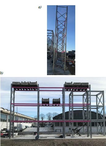
The rack analyzed is fully braced in the cross-aisle direction with diagonal braces extending from top to bottom (Fig. 1a). Diagonals are designed not to buckle under seismic actions. In the down-aisle direction, the rack behaves like a moment-resisting frame (Fig. 1b). The investigated system is a medium-rise double-entry pallet rack. Storage levels have a constant inter-story height of 2000 mm and a bay length of 2700 mm. Pallets are placed on beams. Pallets of 800kg each at different bays and levels are placed. The layout adopted in experimental tests with the distribution of the vertical live loads is shown in Fig. (1b).
The rack is made of thin-walled cold-formed steel open sections with different profiles for the different components. Uprights are produced from S350 steel grade (nominal yield stress of 350 MPa). Uprights have a perforated open section, whose ultimate capacity has been investigated through experimental tests under compression and bending [57]. The diagonal brace steel grade is S250 (nominal yield stress of 250 MPa). Diagonal braces have a 25mm x 25mm x 8mm lipped channel section, which is 1.5mm thick. Diagonals are assembled flange-to-flange, and one M8 bolt class 8.8 [58] is adopted to join the diagonals to the upright. The non-linear response of diagonal braces has been investigated [59], where testing procedures, instrumentations and detailed experimental results can be found.
In the down-aisle direction, beam-to-column connections are formed by a beam with a hollow tubular cross section (height/width/thickness = 120/40/2 mm). The beam end section is welded to a connector with 5 tabs. The moment-rotation curve of rack connection is determined in previous tests [60] using the procedure described in EN 15512 [61].
2.2. Loading Protocol
Hammer tests and impact tests simulating the operating forklift truck impact are carried out to evaluate the propagation of acceleration between adjacent upright frames and the magnitude of strains recorded on diagonal braces placed at the bottom of the upright frames.
In Table 1, the live load at different levels and the loading protocol for each test are listed.
| Test |
Total Load [kN] Level 1 |
Total Load [kN] Level 2 |
Total Load [kN] Level 3 |
Loading protocol |
|---|---|---|---|---|
| HT1base | 0 | 16 | 48 | Hammer test – impulse at 0.4m – cross-aisle direction |
| HT2base | 0 | 16 | 48 | Hammer test – impulse at 0.4m – cross-aisle direction |
| HT11°level | 0 | 16 | 48 | Hammer test – impulse at first level – cross-aisle direction |
| HT21°level | 0 | 16 | 48 | Hammer test – impulse at first level – cross-aisle direction |
| FI | 0 | 16 | 48 | Forklift truck impact at the first level- cross-aisle direction |
HTNj, identifies the Hammer Test number N in which the impulse is applied at the j position, where j=base means that the impact is applied at 0.4m from the ground according to the UNI EN 15512 and j=1°level means that the hit is applied at the first load level.
In the FI test, the Forklift truck impact during pallet handling is simulated (Fig. 2a).
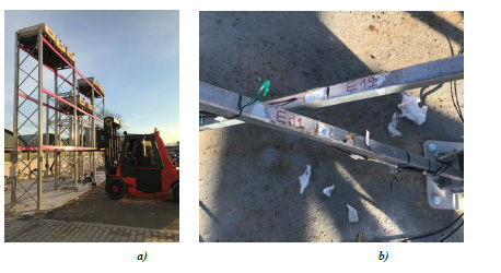
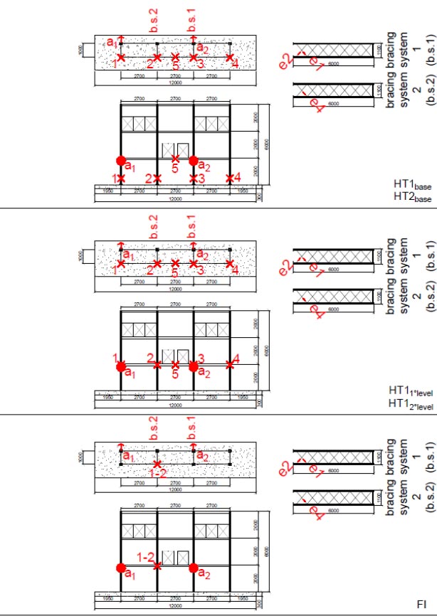
Different types of instrumentations are used for data recording. Strain gauges are adopted for measuring the axial strains developing in the diagonal braces (Fig. 2b). Accelerometers are used to measure accelerations in the horizontal direction along the cross-aisle direction of the rack. In Fig. (3), the position of monitoring devices is highlighted, ai identifies the position of the i-th accelerometer, and the arrow indicates the direction of the measurement, ej identifies the position of the j-th strain gauge placed on a diagonal. The letter “X” identifies the point where the impact is applied, and the related number identifies the sequence of the impulses.
3. RESULTS AND DISCUSSION
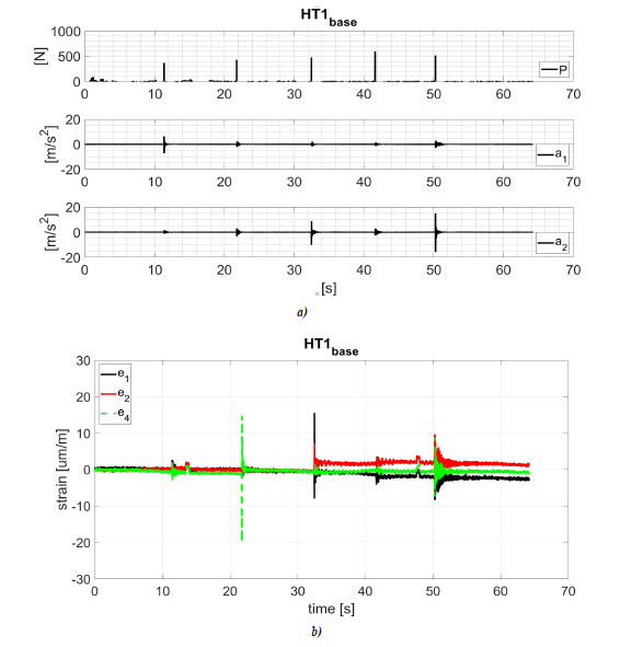
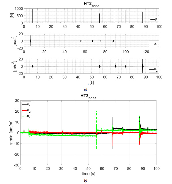
The load (P), acceleration (ai) and strain (ei) time history recorded during test HT1base and HT2base are shown in Figs. (4 and 5). The maximum value of the recorded load and related maximum acceleration and strain are listed in Tables 2 and 3.
| Accelerometer (HT1base) |
Impulse [N] | ||||
|---|---|---|---|---|---|
| 1° | 2° | 3° | 4° | 5° | |
| 369 | 431 | 479 | 597 | 516 | |
| a[m/s2] - acceleration | |||||
| a1 | 7 | 2,5 | 2,1 | 1,3 | 2,9 |
| a2 | 1,6 | 3,5 | 10,2 | 2,9 | 15,6 |
| a1/a2 | 4,4 | 0,7 | 0,2 | 0,4 | 0,2 |
| a2/a1 | 0,2 | 1,4 | 4,9 | 2,2 | 5,4 |
| Strain gauge (HT1base) |
Impulse [N] | ||||
| 1° | 2° | 3° | 4° | 5° | |
| 369 | 431 | 479 | 597 | 516 | |
| e - strain | |||||
| e1 | 2,4 | 1,9 | 15 | 4,2 | 8,3 |
| e2 | 1 | 1,6 | 7,2 | 3,4 | 9,6 |
| e4 | 2 | 19 | 1,6 | 1,6 | 8,7 |
| e1/e2 | 2,4 | 1,2 | 2,1 | 1,2 | 0,9 |
| e2/e1 | 0,4 | 0,8 | 0,5 | 0,8 | 1,2 |
| Accelerometer (HT2base) |
Impulse [N] | ||||
| 1° | 2° | 3° | 4° | 5° | |
| 946 | 651 | 886 | 844 | 732 | |
| a[m/s2] - acceleration | |||||
| a1 | 15,3 | 3,4 | 3,0 | 2,5 | 3,9 |
| a2 | 4,0 | 3,9 | 20,9 | 6,1 | 18,9 |
| a1/a2 | 3,8 | 0,9 | 0,1 | 0,4 | 0,2 |
| a2/a1 | 0,3 | 1,1 | 7,0 | 2,4 | 4,8 |
| Strain gauge (HT2base) |
Impulse [N] | ||||
| 1° | 2° | 3° | 4° | 5° | |
| e - strain | |||||
| e1 | 2,5 | 2,7 | 15,1 | 1,7 | 15,6 |
| e2 | 2,1 | 2,2 | 12,5 | 2,1 | 11 |
| e4 | 3,1 | 20,5 | 7,3 | 0,5 | 15,8 |
| e1/e2 | 1,2 | 1,2 | 1,2 | 0,8 | 1,4 |
| e2/e1 | 0,8 | 0,8 | 0,8 | 1,2 | 0,7 |
Experimental results highlight the reduction in the acceleration between adjacent upright frames. For an impact slight lesser than 1000N at 0.4m from the ground (Fig. 5), the maximum recorded acceleration on the impacted upright is about 20m/s2 and about 3.5 m/s2 at the upright placed two bays closed (the value of acceleration a1 and a2 for the impulse number 1 and 3 in Table 3). The acceleration on the adjacent upright is about 4 m/s2 (the value of acceleration a1 and a2 for impulse number 2 in Table 3).
Experimental results highlight the maximum strain on diagonal braces placed at the bottom of adjacent upright frames in the hammer test. For an impact slight lesser than 1000N at 0.4m from the ground, the strain on diagonals connected to the impacted upright is about 15µm/m and 2.5 µm/m at the diagonal brace placed on the adjacent upright frame (the value of strain e1, e2, and e4 for the impulse number 2 and 3 in Table 3). In both cases, the measured strains are lesser than the diagonal yielding strain 1190µm/m, highlighting the braces to remain in the elastic field.
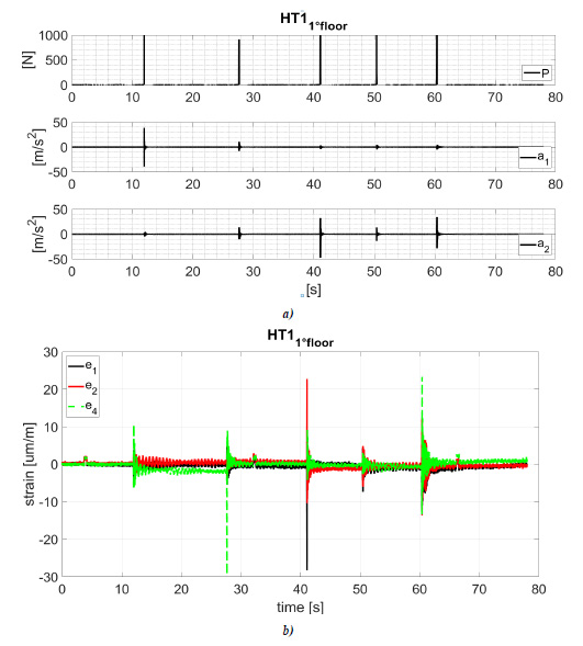
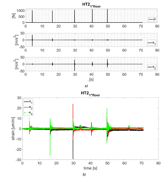
The load (P), acceleration (ai) and strain (ei) time history recorded in test HT11°floor and HT21°floor are shown in Figs. (6 and 7). The maximum value of the recorded load and related maximum acceleration and strain are listed in Tables 4 and 5.
| Accelerometer (HT11°floor) |
Impulse [N] | ||||
| 1° | 2° | 3° | 4° | 5° | |
| 1158 | 915 | 995 | 1171 | 1048 | |
| a[m/s2] - acceleration | |||||
| a1 | 38,7 | 10,8 | 3,5 | 4,5 | 4,5 |
| a2 | 4,5 | 13,7 | 32,2 | 13,5 | 34,5 |
| a1/a2 | 8,6 | 0,8 | 0,1 | 0,3 | 0,1 |
| a2/a1 | 0,1 | 1,3 | 9,2 | 3,0 | 7,7 |
| Strain gauge (HT11°floor) |
Impulse [N] | ||||
| 1° | 2° | 3° | 4° | 5° | |
| 1158 | 915 | 995 | 1171 | 1048 | |
| e - strain | |||||
| e1 | 5,1 | 6,4 | 28,3 | 7,3 | 13,7 |
| e2 | 2,4 | 3,8 | 22,8 | 6 | 13,6 |
| e4 | 10,1 | 29,4 | 3,8 | 2,5 | 17,8 |
| e1/e2 | 2,1 | 1,7 | 1,2 | 1,2 | 1,0 |
| e2/e1 | 0,5 | 0,6 | 0,8 | 0,8 | 1,0 |
| Accelerometer (HT21°floor) |
Impulse [N] | ||||
| 1° | 2° | 3° | 4° | 5° | |
| 1018 | 1002 | 1053 | 1110 | 1127 | |
| a[m/s2] - acceleration | |||||
| a1 | 38 | 12,4 | 4,1 | 4 | 4,2 |
| a2 | 3,3 | 13,1 | 32,1 | 15,4 | 36,1 |
| a1/a2 | 11,5 | 0,9 | 0,1 | 0,3 | 0,1 |
| a2/a1 | 0,1 | 1,1 | 7,8 | 3,9 | 8,6 |
| Strain gauge (HT21°floor) |
Impulse [N] | ||||
| 1° | 2° | 3° | 4° | 5° | |
| 1018 | 1002 | 1053 | 1110 | 1127 | |
| e - strain | |||||
| e1 | 5,2 | 6,8 | 29,2 | 5,4 | 11,4 |
| e2 | 2,8 | 5,2 | 24 | 6,3 | 11,3 |
| e4 | 10,3 | 25,8 | 10 | 4,1 | 19,6 |
| e1/e2 | 1,9 | 1,3 | 1,2 | 0,9 | 1,0 |
| e2/e1 | 0,5 | 0,8 | 0,8 | 1,2 | 1,0 |
Experimental results highlight the reduction in the acceleration between adjacent upright frames. For an impact of about 1000N at the first load level (Figs. 7 and 8), the maximum recorded acceleration on the impacted upright is about 35m/s2, and it is about 4 m/s2 (ratio 0.1) at the upright placed two bays closed (the value of acceleration a1 and a2 for the impulse number 1 and 3 in Tables 4 and 5. The acceleration on the adjacent upright is about 10 m/s2 (the value of acceleration a1 and a2 for impulse number 2 in Tables 4 and 5).
Regarding the value of the recorded maximum strain at the diagonal braces placed at the bottom of the upright frame, it can be observed that for an impact of about 1000N at the first load level, the strain on the impacted upright is about 30µm/m and 5 µm/m at the diagonal placed on the adjacent upright frame (the value of strain e1, e2 and e4 for the impulse number 2 and 3 in Tables 4 and 5). In both cases, the measured strains are less than the yielding strain, confirming the diagonals remain in an elastic field.
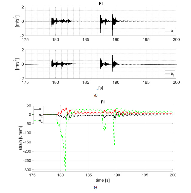
Acceleration (ai) and strain (ei) time history recorded during test FI are shown in Fig. (8), and the maximum values at different impacts are listed in Table 6.
The maximum acceleration due to the forklift truck impact during the pallet handling is about 2.4 m/s2, a value smaller than those obtained in the hammer tests. A similar value of a1 and a2 highlights that the upright frames adjacent to the impacted one are affected by about the same acceleration and actions (Table 6). The maximum recorded strain is greater than that measured during hammer tests (305.6 µm/m, Table 6). The difference between the maximum strains measured by e1 and e4 highlights a reduced capacity of the racking system in the redistribution of forces between adjacent upright frames. As expected, the diagonals of the impacted upright frame are the critical members. A similar value of e1 and e2 (e1/e2≈1), obtained in all tests, highlights that compressed and tensile diagonals work in parallel.
| Accelerometer (FI) |
a[m/s2] - acceleration | ||
| a1 | 0,8 | 1,6 | 2,4 |
| a2 | 0,6 | 0,8 | 1,5 |
| Strain gauge (FI) |
e - strain | ||
| e1 | 28,8 | 19,9 | 23,4 |
| e2 | 35,7 | 22,1 | 26,3 |
| e4 | 305,6 | 86,4 | 165,9 |
CONCLUSION
Experiments on a full-size selective rack subjected to the impact of a forklift truck during the pallet handling and hammer tests were performed. The propagation of the acceleration among adjacent bracing frames was investigated with the magnitude of the strains in diagonal braces of upright frames.
In hammer tests, in which about the same load suggested by standard codes (EN 15512 and Australian Standard AS 4084) for manually operated forklift trucks has been reproduced, recorded accelerations and strains were different from those produced by the simulated impact of a forklift truck. A load of about 1 kN applied at 0.4 m from the ground or at the first load level led to a maximum acceleration of 20 m/s2 and 35 m/s2, respectively, recorded by an accelerometer placed at the first load level on the impacted upright frame. The maximum strain was 30 µm/m, recorded on the bottom diagonal at the impacted upright frame. The impact of a forklift truck during the pallet handling effectively produced an acceleration of 2.4 m/s2 and a strain of 305.6 µm/m.
Moreover, experimental results highlighted that an accelerometer every two spans was enough to recognize whether the monitored racking system was accidentally hit. Nevertheless, recorded accelerations could be used to estimate the stress pattern on structural members only by adopting a finite element numerical model developed for this purpose and calibrated on experimental results. In common practice, accelerometers are suggested to warn when the rack is stricken, while strain gauges are proposed for a reliable estimation of stresses on non-impacted structural members. The assessment of the damage to the impacted members requires future investigations. Finally, results showed that for the investigated racking system, the number of strain gauges could be reduced, considering that forklift truck impact and induced stress on structural members can be detected by applying only a strain gauge at one bottom diagonal of the upright frame every two spans.
LIST OF ABBREVIATIONS AND SYMBOLS
| CFS | = Cold-Formed-Steel |
| FE | = Finite Element |
| P | = Load |
| ai | = Acceleration |
| ei | = Strain |
CONSENT FOR PUBLICATION
Not applicable.
AVAILABILITY OF DATA AND MATERIALS
The data that support the findings of this study are available within the article.
FUNDING
None.
CONFLICT OF INTEREST
Dr. Gusella is the associate editorial board member of The Open Civil Engineering Journal.
ACKNOWLEDGEMENTS
Declared none.

