All published articles of this journal are available on ScienceDirect.

Experimental Study on Seismic Behavior of Steel Plate Shear Walls with Connections in the Weak Axis of PEC Columns
Abstract
Introduction:
Steel Plate Shear Walls (SPSW) with Partially Encased Composite Columns (PEC) are proposed to address the issues of local buckling failures during earthquakes and insufficient energy dissipation capacity of steel plate walls.
Methods:
In this study, cycle loading tests were conducted on three PEC-SPSW specimens with varying parameters to investigate the stress distribution, failure mode, hysteresis curve, skeleton curve, and energy dissipation performance of SPSW with weak axis connections in PEC columns specimens.
Results:
The results showed that specimens with weak axis connections in PEC columns performed well during seismic tests. Incorporating PEC columns into a steel plate shear wall structure can prevent local buckling of the edge column, improve the post-buckling strength of the thin steel plate wall, and enhance the overall seismic performance of the structure. Increasing the width-to-thickness ratio of the PEC column flange, as well as the settings of the stiffened plates, can significantly improve the structure's energy dissipation capabilities.
Conclusion:
This study serves as a reliable reference for the use of this type of structure in practical engineering.
1. INTRODUCTION
Steel Plate Shear Walls (SPSW) are structures that effectively resist lateral forces and are often used in high-rise buildings [1]. The force mechanism is that the embedded steel plate wall provides lateral resistance to the structure by using its own post-buckling strength under the anchoring effect of the surrounding frame. However, the post-buckling strength of the thin plate causes significant additional stresses on the edge column, eventually leading to local buckling of the traditional steel edge column's flange. As a result, the post-buckling strength of the embedded steel plate cannot be fully utilized [2].To improve the performance of structural frame columns and ensure the safety of the main structure, many scholars have turned their attention to partially encased concrete composite (PEC) columns which offer high strength, stiffness, and high flexural performance and have conducted a lot of related research [3-5]. Researchers have also conducted relevant research on SPSWs with PEC columns to solve the problems, such as the edge column flange of an SPSW being prone to local buckling and the steel plate's post-buckling strength not being fully utilized.
Robert's experiments [6] indicated that PEC columns could provide anchoring force for steel plates. Driver et al. [7] designed three SPSW specimens with PEC columns and conducted cyclic loading tests. The results showed that PEC columns could significantly improve the structure's initial stiffness and bearing capacity. When acting as edge columns in SPSW structures, PEC columns improved the structure's bearing capacity, enhanced the anchoring effect on thin steel plates, and reduced local buckling of the column flange [8]. Dastfan [9] conducted quasi-static tests on SPSW structures with PEC columns connected to RBS frames. The results indicated that PEC columns improved the structure's ultimate bearing capacity and hysteretic performance under cyclic loading, which has a significant impact on seismic performance. Yu [10] conducted experimental loading and finite element simulation on two SPSWs with PEC columns and X-type and C-type links in H-shaped columns. The study found that PEC columns with two types of links significantly improved their bearing capacity, initial stiffness, and energy dissipation performances, and the bearing capacity of X-type links was significantly higher than that of C-type links. The test of SPSW with the PEC column’s two new structures was performed by Yin [11], and the results indicated that the PEC column provided enough anchoring effect for the thin steel plate. The above research showed that introducing PEC columns into the SPSW structure can effectively improve the initial stiffness, bearing capacity, energy dissipation performance of the structure, and the seismic performance of the structure. It can provide effective anchorage for the thin steel plate when the stiffness and strength of the edge column of the SPSW structure are large enough and the post-buckling strength of the thin steel plate is more fully exerted.
Research on SPSW structure with PEC columns (strong axis) has shown good seismic performance. Relevant finite element simulations and experimental research have been conducted on PEC columns (weak axis) to further explore their performance. A full-scale study of the energy dissipation of PEC columns (weak axis) fabricated with thin-walled built-up sections was conducted by Fang [12]. Liew, JYR [13] proposed a unified assessment method for the changes in axial force and strength curve of partially encased concrete-filled steel composite columns with different steel and concrete grades. A database was established based on experimental data, and the accuracy of the prediction method was studied with different design parameters. The results showed that the analysis results agreed with the experimental results, indicating that the method can provide reasonable predictions for the moment interaction curves of steel and concrete composite columns. Furthermore, the method was improved on the basis of EC4, making the prediction results more accurate and providing a unified method for the design of steel and concrete composite columns. In summary, this method provided engineers with a reliable reference and helped to improve the stability and safety of structures. The PEC columns (weak axis) were then connected to weakened section steel beams, and seismic tests were performed using a scaled model of the frame. The results showed that a plastic hinge formed at the weakened part of the beam end of the specimen and the PEC columns, and the energy dissipation capacity of the structure was fully utilized [14]. Feng [15] investigated the seismic performance of a PEC column (weak axis) steel beam composite frame, which showed good collapse resistance. By conducting experimental research and numerical simulation, Li [16] studied the seismic performance of weak-axis frame joints. Fang [14] designed a two-story, single-span composite frame specimen featuring a PEC section for the column's weak-axis direction and a weakened end plate for the beam to form an ideal plastic hinge. Through cyclic loading tests and analysis of the hysteresis and other mechanical properties, the study found that designing a weakened section at the end of the beam moved the formation of plastic hinges away from the nodal region. This design strategy significantly improved the structural hysteresis performance and created an ideal plastic hinge between the beam end and the column base, leading to optimal structural behavior. The results indicated that weak-axis connection joints were capable of good seismic performance and good energy dissipation.
Therefore, the PEC column (weak axis) possesses good mechanical properties, and the frame structure of the PEC column with weak-axis connection also exhibits excellent energy dissipation performance, which fully utilizes the seismic performance of the structure. In practical engineering, the use of SPSW structures with a PEC column weak-axis connection is common, but there are few relevant codes and literature regarding SPSW structures with a PEC column (weak axis) connection. As a result, this type of structure lacks a reference for practical engineering applications. Therefore, it is of great significance to study the seismic performance of SPSW with a PEC column (weak axis), which can provide a favorable reference for the application of this structure in practical engineering.
In this study, three specimens of SPSW structures with PEC columns (weak axis) were designed with varying parameters, and quasi-static tests were conducted to evaluate the stress distribution, failure mode, hysteresis curve, skeleton curve, and energy dissipation of each specimen. The results showed that this type of structure exhibited good energy dissipation performance under cyclic loading. The width-to-thickness ratio of flanges for PEC columns and the height-to-thickness ratio for embedded thin steel plates were found to have a significant impact on seismic performance of this type of structure. To assess the cyclic loading hysteresis performance of this structural type, the failure mode of the steel plate under the framing effect of PEC columns with weak-axis connection was evaluated, and the development and distribution of the tension field of the steel plate after buckling in PEC column (weak-axis) steel plate shear walls were investigated. The aim was to ensure structural safety and reliability and provide a reference for practical engineering applications with more clarity and fluency.
2. MATERIALS AND METHODS
2.1. The Design of Steel Plate Shear Walls with Connections in the Weak Axis of PEC Columns
2.1.1. Specimen Design
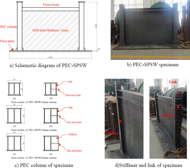
Based on a 1/3 scale model of a 16-story office building and referring to the Chinese “Code for Seismic Design of Buildings” (GB 50011-2010,2016) [17], three specimens of SPSW with connections in the weak axis of PEC columns with varying parameters were designed and numbered PEC-SPSW-2, PEC-SPSW-4, and PEC-SPSW-6. The specimens consisting mainly of edge columns, frame beams, thin steel plates, concrete and other ancillary components, with all components, were connected by welding. The frame beams of the three specimens were H-shaped steel with a cross-sectional size of H100 mm × 100 mm × 6 mm × 8 mm and a length of 1800 mm. PEC-SPSW-6 was welded with stiffeners at the connection between the web of the PEC column and the thin steel plate. The details of the specimens are shown in Fig. (1). The geometric parameters of the specimens are shown in Table 1.
The main difference between PEC-SPSW-2 and PEC-SPSW-4 was the section size of the edge column. Specifically, the section size of PEC-SPSW-2 was 120mm × 120mm × 4mm × 6mm, while the section size of PEC-SPSW-4 was 140mm × 140mm × 4mm × 6mm. Apart from this, all other parameters were the same. Similarly, the primary difference between PEC-SPSW-6 and PEC-SPSW-4 was that PEC-SPSW-6 included stiffening plates at the connection of PEC columns and thin steel plates. Again, all other parameters were identical. The PEC columns of the three specimens were primarily composed of H-shaped steel, concrete, and tie reinforcement.
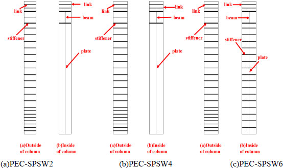
Additionally, a stiffening plate was pre-installed within the PEC-SPSW-6 column. The design process for the PEC-SPSW-2 and PEC-SPSW-4 columns was consistent, with link reinforcements with a diameter of 6mm welded within the H-shaped steel columns. The distance between the link reinforcements and the edge of the steel column flange was 20mm, and the spacing between the link reinforcements was 60mm. Link reinforcements at the column base and top require denser spacing of 30mm, and a stiffening plate was installed within the steel column at the same height as the beam-column connection. The design process for PEC-SPSW-6 was mostly the same as the previous two specimens, with an additional stiffening plate pre-installed at the connection point between the steel column and thin steel plate, with a spacing of 60mm. The detailed design drawings of the PEC columns for the three specimens are shown in Fig. (2). The slenderness ratio of the PEC column was calculated as follows:
 |
(1) |
 |
(2) |
 |
(3) |
 |
(4) |
 |
(5) |
 is the slenderness ratio of the PEC column, L is the length of the PEC column, I0 is the converted section moment of inertia, A0 is the converted sectional area, Ic is the moment of inertia of concrete section, Ia is the section moment of inertia of the steel, Ea is the elastic modulus of the steel, Ec is the elastic modulus of concrete
| Number | Cross-sectional Size of PEC /mm | Thickness of Embedded Steel Plate /mm | Strength Grades of Concrete | Whether to Set Stiffeners | Slenderness Ratio of H-shape Steel | Flange Width-thickness Ratio of PEC Columns | |
|---|---|---|---|---|---|---|---|
| PEC-SPSW-2 | H120 × 120 × 4 × 6 | 2 | C30 | - | 27.6 | 10 | |
| PEC-SPSW-4 | H140 × 140 × 4 × 6 | 2 | C30 | - | 23.7 | 11.67 | |
| PEC-SPSW-6 | H140 × 140 × 4 × 6 | 2 | C30 | stiffener | 23.7 | 11.67 | |
2.2. Experimental Study on Steel Plate Shear Walls with Connections in the Weak Axis of PEC Columns
2.2.1. Material Properties
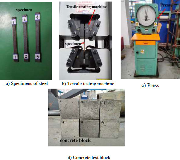
The steel parts of the specimen were made of Q235 steel, and samples of the steel materials were taken to conduct a tensile test in accordance with the Chinese standard “Metallic materials—Tensile testing at ambient temperature” (GB/T228-2002) [18]. First, it was necessary to prepare the steel specimens and calibrate the testing equipment. The specimen was properly installed onto the testing machine and then uniformly and slowly stretched until pulled apart. The relevant data was recorded. Fig. (3) shows the schematic diagram of the steel specimen and the tensile testing equipment. The material properties of the steel obtained from the test are shown in Table 2. Extra concrete was reserved when pouring PEC columns to make 6 concrete test blocks. These blocks were cured under the same conditions for 28 days and then placed in a hydraulic press with a capacity of 2000kN to conduct a concrete strength test. The concrete components of the specimens were made of C30 concrete, and six standard cube concrete blocks were produced. The compressive strength test of the concrete was carried out according to the Chinese “Code for Construction Quality Acceptance of Concrete Structure Engineering” (GB50204-2002) [19]. The compressive strength of concrete measured by the test is shown in Table 3.
| Type |
Yield Strength fy/MPa |
Ultimate Strength Fu/MPa |
Elastic Modulus E/MPa |
Elongation δ/% |
|---|---|---|---|---|
| Column | 246 | 439 | 206000 | 24 |
| Beam | 241 | 451 | 220000 | 26 |
| Plate | 238 | 423 | 232700 | 26 |
| Test Block Number | Ultimate Load (kN) |
Cubic Compressive Strength fcu,k(N/mm2) |
|---|---|---|
| 1 | 758 | 33.35 |
| 2 | 742 | 33.17 |
| 3 | 761 | 33.80 |
| 4 | 786 | 35.21 |
| 5 | 769 | 34.51 |
| 6 | 775 | 34.72 |
| Average Value | 763 | 34.13 |
2.2.2. Loading Protocol and Instrument
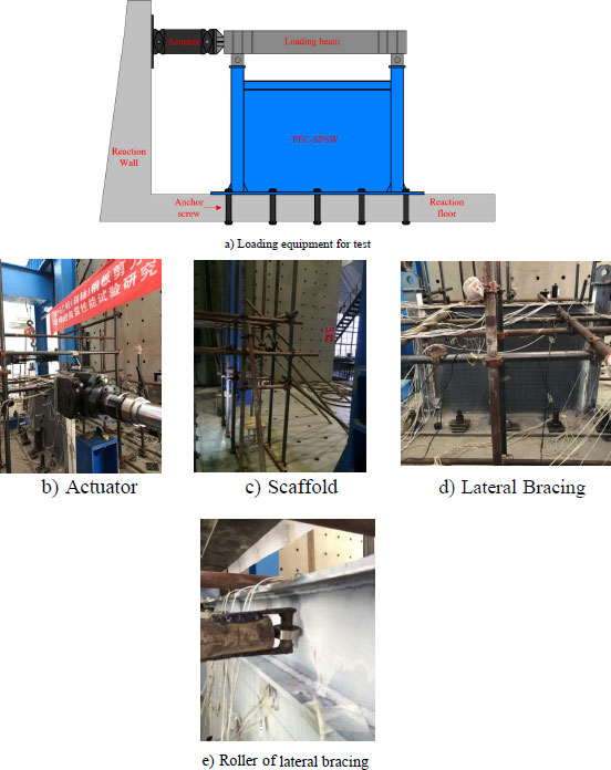
The quasi-static test was performed using an elector-hydraulic servo-programmed actuator (MTS) that can apply a horizontal force of 1000 kN, as shown in Fig. (4b). The actuator was connected to the loading beam, which transmitted horizontal force to the specimen. The loading beam was connected to the top of the specimen columns with 50 mm diameter pins, and the bottom plate of the specimen was fixedly connected to the reaction floor with high-strength bolts of 60 mm in diameter. The device details are shown in Fig. (4a). To prevent the out-of-plane instability of the specimen during loading as shown in Fig. (4c), an overall scaffold was installed outside the specimen, as shown in Fig. (4d and 4e). A lateral support with a pulley was installed in the web area of the beam to constrain the out-of-plane development of the specimen during loading.
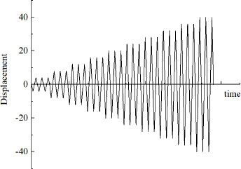
The loading method used for the specimen followed the “Specification of Testing Methods for Earthquake Resistant Building” (JGJT 101-2015, 2015) [20], which utilized a displacement-controlled loading method. The amplitude of the displacement loading is shown in Fig. (5), The specimen on each level was cycled three times, and the interval of the loading was 4mm until the bearing capacity of the specimen significantly decreased. The test was terminated once the specimen was damaged.
2.2.3. Stress Measurement and Analysis
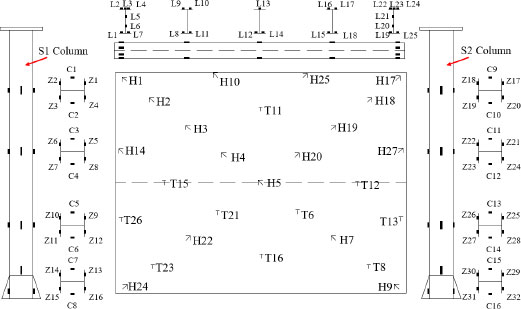
Fig. (6) shows the arrangement of strain gauges at key points on the specimen. During the testing and loading process, these gauges collected data on the strain experienced by the specimen, which was used to calculate the stress. This information was then transmitted to the strain collection device.
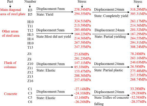
Fig. (7) shows the stress value at key positions of PEC-SPSW-2. As the displacement reached 5mm, the stress on the specimen frame was relatively small, but the main diagonal area of the embedded thin steel plate had entered the elastoplastic state due to the lateral force causing shear and was susceptible to buckling deformation. The low-yield steel began to yield, reaching a maximum stress of 294.35 MPa. In addition, most areas of the specimen remained in the elastic stage. At a displacement of 24 mm, the minimum stress of T11-T13, H14, T15 and T16 regions in the main diagonal of the steel plate ranged from a minimum of 201.52 MPa to a maximum of 308.24 MPa, while most of the area outside the main diagonal of the steel plate was in the yield state. The stress on the edge column and the filled concrete of the specimen increased, and the steel at the column foot reached its yield strength. When the maximum stress of the concrete at the top of the column reached 33.28 MPa, the concrete began to peel off. The main frame of the specimen bore the additional tension generated by the tensile position of the thin steel plate, and the PEC column, with high stiffness and strength, provided a good anchoring effect for the steel plate. The stress development law of PEC-SPSW-4 and PEC-SPSW-6 was basically similar to PEC-SPSW-2. These results demonstrate that introducing the PEC column into the SPSW structure can prevent local buckling of the edge column, increase the anchoring effect on the thin steel plate, and effectively improve the seismic performance of the shear wall structure.
3. RESULTS AND DISCUSSION
3.1. Experimental Phenomenon
The experimental set-up was an electro-hydraulic servo-programmed actuator (MTS) capable of applying a horizontal force of 1000 kN. The test piece loading mode was bidirectional cyclic loading mode.
The loading direction of the test piece and the definition of the edge column: the left column of the test piece was S1, and the right column was S2. The push load was positive, and the pull load was negative. The arrangement of the strain gauge of the test piece is shown in Fig. (8). The strain gauges were carefully positioned and fixed onto the surface of the object being tested in order to accurately measure strain or deformation.
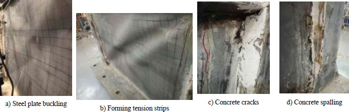
PEC-SPSW-2: During the initial loading period, the components of the specimen were in an elastic state, and the steel plate had a slight bulging defect during the processing, which made it sound, but there was no obvious deformation. When the displacement reached an 8mm cycle, the embedded (Fig. 9) steel plate was in an elastic-plastic state. The above area of the main diagonal appeared to uplift the phenomenon of the plate and gradually developed into a tension band because the top half of the steel plate was close to the action point of the force. When the displacement reached 12 mm cycle, the thin steel plate had formed an obvious tension strip of the main diagonal of the “X-shape” under cyclic load because it will occur breathing effect under cyclic load, and the frame was no phenomenon. When the displacement reached 20 mm, the development of the main diagonal tension strip of the steel plate became more and more obvious, and a small range of tension strip appeared near the main diagonal tension strip. Due to the cyclic load, the steel plate made a violent sound during the push-pull load alternate period, then the concrete outside of the S2 column cracked with the surface peeled off. At this time, the steel plate was in the post-buckling strengthening stage. When the displacement reached 24 mm, the main diagonal tension strip of the steel plate was particularly obvious, and the difference at the maximum deformation was about 10 mm. Thus, the steel plate reached post-buckling strength under the continuous alternation of push-pull loads. There were the phenomena of paint peeling off and the steel plate tearing at the intersection of the main diagonal tension strip of the steel plate because of the continuous alternation of push-pull loads. The embedded steel plate of the specimen finally produced an obvious tension strip. The phenomenon of weld fracture occurred at the connection of the stiffener of the PEC column. In addition, the frame beam had a slight out-of-plane offset, and the concrete cracks of the PEC column gradually increased. When the displacement reached 28 mm, the steel plate generated a huge noise, then the tension strip area of the steel plate increased and was in the yield state. The end flange of the frame beam occurred at the local buckling, and the concrete fragments of the PEC column fell off in large quantities. At this time, the specimen was basically in a failure state, and the bearing capacity no longer increased with the displacement. The ultimate bearing capacity of the specimen was 470 kN.
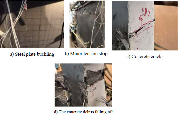
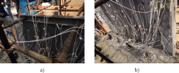
During the elastic stage of the first two loading cycles, the steel plate exhibited slight bulging and produced a faint sound due to the initial defect. As the specimen was loaded to 4mm in the third cycle, the sound from the steel plate gradually increased. By the time the displacement reached 8mm, a small primary diagonal tension strip had formed. When the displacement reached 12mm, the primary diagonal tension strip on the steel plate became significant, and several secondary tension strips appeared. As the displacement increased to 16mm, the tension strip on the steel plate expanded, and cracks appeared on the concrete at the top of the PEC column. Some concrete had even fallen from the contact area between the concrete and steel column. Although the concrete cracks continued to develop as the displacement reached 20mm, there was no obvious deformation on the PEC column. However, at 28mm, the end flange of the frame beam buckled locally, and there was a slight out-of-plane displacement. Concrete debris fell off from the PEC column, and the load-bearing capacity of the structure began to decrease. The test was terminated, and the ultimate bearing capacity of the specimen was determined to be 468KN. The test phenomenon is shown in Fig. (10).
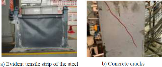
PEC-SPSW-6: PEC-SPSW-6 exhibited similar phenomena to PEC-SPSW-4 and PEC-SPSW-2. The initial behavior was the same until a displacement of 12mm was reached. At 16mm, the main diagonal tension strip began to develop and enlarge, and concrete started to fall off at the contact point between the concrete and steel column. When the displacement reached 20mm, the main diagonal tension strip alternated, and the paint peeled off in the joint area of the tension strip. Diagonal cracks appeared in the concrete at the base of the column. As the displacement increased to 24mm, the frame beam experienced out-of-plane displacement, and numerous cracks appeared in the concrete. The thin steel plate exhibited large-scale yielding, and multiple secondary tension strips appeared. Concrete debris fell off, and the load capacity of the specimen began to decline until the test was terminated. The test phenomenon is shown in Fig. (11).
3.2. Failure Mode
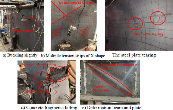
The failure modes of the three specimens under cyclic loading were similar. As shown in Fig. (12a), the displacement of the specimen reached 5.6mm (the value of the drift angle is 1/250), and the entire structure was in an elastic state with no obvious deformation, but the embedded thin steel plate exhibited slight buckling. As shown in Fig. (12b), the displacement of the specimen reached 15mm (the value of the drift angle is 1/100), the thin steel plate entered the elastoplastic state, forming an obvious tension strip, while the edge frame remained in the elastic state without significant change. As shown in Fig. (12c), as the displacement of the specimen reached 24 mm, most of the structure entered the plastic state, and the thin steel plate formed multiple “X-shaped” tensile strips. The steel plate folded and exhibited slight tearing at the intersection of the tensile strips under push-pull load. As shown in Fig. (12d), the displacement of the specimen reached 28 mm, the foot and top area of the PEC column began to yield concrete cracks, and some concrete fragments fell. The end and mid-span of the frame beam showed obvious bending deformation because the fragments were falling. The end and mid-span of the frame beam showed obvious bending deformation due to the increase in the flange width-to-thickness ratio of the PEC column, resulting in increased stiffness of the edge column and mismatched stiffness of the beam, column, and embedded thin steel plate.
3.3. Hysteresis Curve
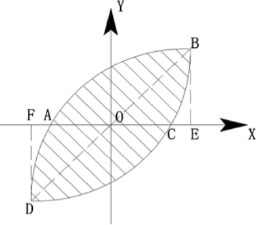
The energy dissipation coefficient E was calculated by the hysteretic curve of the specimen under cyclic load, and it reflects the energy dissipation of the structure. The expression for the energy dissipation coefficient expression is as follows:
 |
(6) |
As shown in Fig. (13), SABC+CDA is the area enclosed of the hysteresis loop and S is the area of the OBE and ODF triangles.
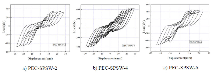
Fig. (14) displays the hysteresis curves of three specimens, namely PEC-SPSW-2, PEC-SPSW-4 and PEC-SPSW-6. During the loading process, the hysteresis curve of all three specimens was fusiform and followed a similar trend. The bearing capacity of the specimen did not decrease significantly. Except for PEC-SPSW-2, which experienced a significant decrease in stiffness and bearing capacity due to the formation of tension strips and cracks at 24 mm, ultimately resulted in failure at 28 mm. As a result, the specimen was destroyed. In comparison, the hysteresis curve of PEC-SPSW-4 was fuller, and the stiffness and bearing capacity were significantly improved. And the bearing capacity was significantly improved. This could be attributed to the increased flange width-to-thickness ratio of the PEC column, which enhanced the anchoring effect of the edge frame on the thin steel plate, allowing the post-buckling strength of the steel plate to play a more significant role. The stiffness and bearing capacity of the specimen did not decrease significantly under the push load, it began to decrease when the displacement of the tensile load reached 28 mm, and the tensile and compressive loads were basically the same. The mechanical properties of PEC-SPSW-4 were better than those of PEC-SPSW-2 because PEC-SPSW-4 increased the flange width-to-thickness ratio of PEC columns, while the increase of the flange width-to-thickness ratio of PEC column increased the stiffness and strength of the edge column and enhanced the anchoring effect of the edge frame on the thin steel plate that makes the post-buckling strength of the steel plate play a significant role. Thus tension strip distribution of the thin steel plate was more uniform. Observing the hysteresis curve of PEC-SPSW-6, it was found that the initial stiffness of the specimen was significantly improved, but the “pinch” in the curve was more evident. The overall bearing capacity of the structure was greatly improved because the PEC-SPSW-6 had stiffeners at the connection between the PEC column web and the embedded thin steel plate. The setting of stiffeners improved the stiffness of the edge column and the restraint effect on the end of the thin steel plate and increased the initial stiffness of the structure. The stiffness of the edge column significantly improved, but the stiffness of the frame beam did not increase, resulting in a lower stiffness of frame beam. Finally, there was a serious mismatch in beam-column stiffness. The frame beam could not withstand the load change, it caused the out-of-plane instability prematurely during the loading process, the structure failed prematurely, and the energy dissipation could not be fully utilized.
3.4. Skeleton Curve and Stiffness Analysis
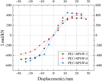
As shown in Fig. (15), the skeleton curves of the three specimens exhibited similar development trends, and the push-pull loads were nearly identical. However, there were significant differences in their mechanical properties:
(1) PEC-SPSW-2 had a yield displacement of 7.92 mm and a yield load of 240.65 kN. The load reached a peak of 344.38 kN at a displacement of 15 mm and then gradually decreased until the specimen failed at 28 mm. The stiffness and bearing capacity of this specimen were significantly lower than those of the other two specimens due to the formation of tension strips and cracks in the steel plate at 24 mm displacement.
(2) PEC-SPSW-4 exhibited a significantly higher initial stiffness and ultimate bearing capacity than PEC-SPSW-2. Its ultimate bearing capacity was 404.43 kN, 17.4% higher than that of PEC-SPSW-2. This improvement was mainly attributed to the increasing flange width-thickness ratio of the PEC column, which enhanced the stiffness and strength of the edge column and improved the anchoring effect of the edge frame on the thin steel plate. Thus, the post-buckling strength of the steel plate was fully utilized, resulting in more uniform distribution of the tension strips.
(3) The ultimate bearing capacity of PEC-SPSW-6 is 450.09 kN, which was 11.3% higher than that of PEC-SPSW-4. It showed that the stiffeners were set at the connection between the web of the PEC column and the embedded thin steel plate, which effectively avoided the local buckling of the thin steel plate due to stress concentration, enhanced the integrity of the steel plate with the edge column, and significantly improved the initial stiffness and bearing capacity of the structure. However, the stiffness of the frame beam did not increase, resulting in a lower stiffness of the frame beam, which caused premature out-of-plane instability during the loading process, leading to premature failure of the structure and incomplete utilization of energy dissipation.
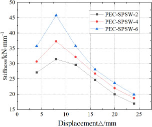
Fig. (16) shows the stiffness degradation curve of three specimens; they all exhibited a similar pattern of stiffness degradation. During the initial loading period, the PEC column provided sufficient stiffness for the structure, and the stiffness of the specimen increased. In the middle stage of loading, the steel plate had a tension strip, and the PEC column needed to bear the additional tension generated by the horizontal force and the post-buckling strength of the thin plate. At this time, the PEC column began to yield locally, and the stiffness of the specimen began to degrade. At the end of the specimen loading, most areas of the structure into plasticity; thus, the stiffness degradation was more serious. Comparing the stiffness of the three specimens, it was found that the larger the width-thickness ratio of the flange of the PEC column, the greater the stiffness of the structure.
| Specimens | Load Displacement/mm | Area (kN·mm) | Area (kN·mm) | Energy Dissipation Coefficient/E |
|---|---|---|---|---|
| PEC-SPSW-2 | 12 | 6811 | 4252 | 1.60 |
| 24 | 14405 | 9733 | 1.48 | |
| PEC-SPSW-4 | 12 | 8414 | 4892 | 1.72 |
| 24 | 16714 | 10853 | 1.54 | |
| PEC-SPSW-6 | 12 | 9656 | 5109 | 1.89 |
| 24 | 19185 | 11409 | 1.68 |
3.5. Energy Dissipation Performance
The energy dissipation coefficient of the three specimens is shown in Table 4. Each specimen had a large area enclosed of the hysteresis loop and good energy dissipation. While comparing PEC-SPSW-2 and PEC-SPSW-4, it was found that the larger the width-to-thickness ratio of the flange of the PEC column, the larger the area enclosed of the hysteresis loop and the energy dissipation coefficient at 12 mm and 24 mm cycles. The area enclosed of the hysteresis curve of the PEC-SPSW-4 at 24 mm was about 16% higher than that of the PEC-SPSW-2, indicating that when the flange width-thickness ratio of the PEC column increased, the stiffness and bearing capacity of the structure also increased, which enhanced the anchoring effect of the edge column on the embedded steel plate. The post-buckling strength of the thin plate was more fully exerted. The PEC-SPSW-6 had stiffeners at the connection between the flange of the PEC column and the steel plate; thus that the area enclosed of the hysteresis curve was about 15% higher than that of PEC-SPSW-4, indicating that the connection between the weak axis of the PEC column and the thin plate was set and the stiffeners could effectively improve the energy dissipation of the structure.
CONCLUSION
This paper investigated the use of partially Encased Composite Columns (PEC column) in Steel Plate Shear Walls (SPSW). The specimens of the PEC-SPSW were tested. To analyze the stress, experimental phenomenon, failure mode, skeleton curve, and energy dissipation of PEC-SPSWs were examined, and the main conclusions are as follows:
1. The PEC-SPSW structure showed good energy dissipation. The PEC column in the SPSW structure could prevent the local buckling of the flange of the edge column, improved the anchoring effect of the edge column on the embedded thin steel plate, allowed for full utilization of the post-buckling strength of the thin steel plate, and made the tension strips distribution of the steel plate more uniform.
2. The increase of the flange width-thickness ratio of the PEC column effectively improved the bearing capacity and energy dissipation of the structure. Compared with PEC-SPSW-2, the bearing capacity of PEC-SPSW-4 increased by 17.4%, and the area enclosed of the hysteresis loop increased by about 16%.
3. The addition of stiffeners at the connection between the PEC column web and thin steel plate effectively enhanced the integrity of the steel plate and edge column, and the initial stiffness and bearing capacity of the structure were significantly improved. Compared with PEC-SPSW-4, the initial stiffness and ultimate bearing capacity of PEC-SPSW-6 were increased by 16.7% and 11.3%, respectively. The flange width-thickness ratio of the PEC column and stiffeners had a great influence on the seismic performance of the structure.
LIST OF ABBREVIATIONS
| PEC column | = Partially Encased Composite Columns |
| SPSW | = Steel Plate Shear Walls |
CONSENT FOR PUBLICATION
Not applicable.
AVAILABILITY OF DATA AND MATERIALS
The data for study were obtained through testing. The hysteresis curve of the tests was obtained using an MTS, while the stress values were obtained using DH3816N strain gauges. The material properties of the steel were obtained using a metal tensile testing machine, and the concrete strength values were obtained using a 2000kN pressure testing machine. All equipment was properly calibrated before and after the experiments. The data were processed using statistical analysis methods and related software. All data and materials used in this study are available upon request from corresponding author [Z.Y].
FUNDING
The study was supported by the following funding agencies:
1. National Natural Science Foundation of China (NSFC), Grant Number: 51968044.
2. Gansu Provincial Department of Housing and Urban and Rural Construction, Research Project ID: JK2022-06.
CONFLICT OF INTEREST
The authors declare that they have no known competing financial interests or personal relationships that could have appeared to influence the work reported in this paper.
ACKNOWLEDGEMENTS
Authors would like to acknowledge the support from the Lanzhou University of Technology in China for the experimental equipment used in this research.

