All published articles of this journal are available on ScienceDirect.

Damage Characteristics of Surrounding Rock for Large Cross-section Tunnel Bench Blasting Excavation: A Case Study
Abstract
Background:
Drilling and blasting methods of excavating the rock mass will cause a certain degree of damage to the surrounding rock. The damage of surrounding rock caused by tunnel blasting excavation is significant for tunnel support design and long-term tunnel stability study.
Methods:
This study is based on the excavation project of the Longnan tunnel of the Ganzhou-Shenzhen high-speed railway with a bench blasting method of grade III surrounding rocks. The cross-hole acoustic wave method was used to test the acoustic wave velocity of surrounding rock in different parts of the same section of the tunnel after excavation. The distribution characteristics of the damage variable of surrounding rock were analyzed, and the damage depth of the surrounding rock in different parts of the tunnel was determined, revealing the relationship between the degree of damage and the damage depth of the surrounding rock. LS-DYNA numerical simulation software was used to simulate the damage evolution and distribution characteristics of the tunnel surrounding rock under the same working condition with eight cycles of blasting excavation, which was consistent with the acoustic test results.
Results:
The results of acoustic testing and numerical simulation showed the maximum damage of the surrounding rock at the foot of an upper step arch of the bench method tunnel but the minimum damage depth; the maximum damage depth of surrounding rock of the tunnel was located at the bottom of the inversion arch.
Conclusion:
Based on the damage distribution characteristics of the tunnel surrounding rock, the initial supporting bolt length for the Longnan Tunnel Grade III rock was determined to be 3.5 m ~ 4 m based on engineering analogies and relevant specifications.
1. INTRODUCTION
As an efficient and economical means of rock excavation, the drill-blasting method is widely used in the excavation of rock tunnel construction. When explosives explode in the rock, part of the energy is used to break the rock to achieve the purpose of excavation, and part of the energy is transferred to the surrounding rock in the form of blast shock waves, causing damage to the surrounding rock. The study of damage characteristics of tunnel blasting surrounding rock can provide a reference for determining the control value of blasting vibration velocity of tunnel surrounding rock and calculating tunnel support parameters, which is of great significance for ensuring construction safety [1-3].
The bench method is the most commonly used construction method for Grade III, IV, and partial Grade V enclosing rock tunnels. This method has a smaller excavation area, which is beneficial to the stability of the surface, but the bench method also increases the time of disturbance to the surrounding rock. Moreover, the damage evolution of the surrounding rock is more complicated, so it is necessary to study the damage evolution and distribution characteristics of the surrounding rock in the bench-blasting excavation method.
Ji et al. [4] studied the vibration response characteristics of the surrounding rock under the action of tunnel excavation blasting through on-site blasting vibration monitoring and acoustic testing. The distribution of the damage depth of surrounding rock in different parts of the tunnel was examined, and the control value of the blasting vibration velocity of the surrounding rock was proposed. In order to explore the quantitative damage analysis method of laminated surrounding rocks, Ma et al. [5] selected three blasting models, single-hole, double-hole, and four-hole, and analyzed the stress wave propagation, crack extension, and fracture mechanism by LS-DYNA finite element software. Chen et al. [6] used blast-induced damage zone (BIDZ) as the evaluation index and three-dimensional discrete element software (3DEC) to study the impact damage of jointed surrounding rock under blasting excavation and analyzed the effects of geometrical and mechanical properties of joints, tunnel burial depth, and length on the damage depth. It was found that the length and geometric properties of the joints had more obvious effects on tunnel damage. Ling et al. [7] investigated the effect of near-zone stress waves and far-zone vibration generated by repeated blasting on tunnel rocks. Using the field ultrasonic testing method, it was found that the near-zone rock damage was mainly due to the dynamic load generated by the first blast, and the damage of the distant zone rock increased under the effect of multiple blast vibrations. At the same time, LS-DYNA finite element software was used for numerical simulation, and the range of the crack zone obtained from the simulation was more consistent with the field test. None of the above research highlights the difference in damage distribution and evolution characteristics between bench blasting and full-face blasting of the surrounding rock.
In this study, acoustic testing of the tunnel envelope after on-site blasting is carried out in the context of blasting excavation of the Longnan tunnel grade III envelope. Combined with dynamic finite element numerical simulation tools, the damage evolution process of tunnel blasting surrounding rock is numerically simulated. Moreover, the damage evolution and distribution characteristics of the surrounding rock in step blasting excavation are studied, with a view to providing a basis for the design of initial tunnel support anchors.
2. PROJECT OVERVIEW
Longnan tunnel is located in Longnan County and Quannan County, Ganzhou City, Jiangxi Province, and is the longest double-line tunnel in the whole line of Gangshen high-speed railway, with a total tunnel length of 10.24 km, as shown in Fig. (1).
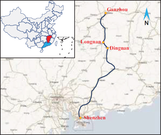
Table 1.
| Grade | Lithology | Length (m) | Method | Proportion | |
|---|---|---|---|---|---|
| II | Granite ( ) ) |
4 400 | Full face | 42.97% | |
| III | Granite () |
1 710 | Bench | 16.70% | 24.90% |
| Sandstone (D2l) | 840 | 8.20% | |||
| IV | Granite () |
680 | Three-bench | 6.64% | 15.09% |
| Sandstone (D2l) | 625 | 6.35% | |||
| Meta-sandstone (ϵ2gt) | 240 | 2.34% | |||
| V | Granite () |
1 331 | Three-bench temporary inverted arch | 12.99% | |
| 245 | Six-step CD | 2.39% | |||
| 39 | Open excavation | 0.38% | |||
| VI | Fault clay | 130 | Other | 1.28% | |
| Hole Type | Quantity |
Length (cm) |
Single Hole Charge (kg) |
Total Charge (kg) |
Delay Group | |
|---|---|---|---|---|---|---|
| Cut hole | First | 6 | 136 | 1.05 | 6.3 | 1 |
| Second | 8 | 293 | 2.25 | 18.0 | 3 | |
| Relief hole | Upper bench | 24 | 260 | 1.5 | 36.0 | 5 |
| 16 | 24.0 | 7 | ||||
| 14 | 21.0 | 1 | ||||
| 14 | 21.0 | 3 | ||||
| Bottom bench | 14 | 260 | 1.5 | 21.0 | 5 | |
| 18 | 27.0 | 7 | ||||
| 14 | 21.0 | 8 | ||||
| Buffer hole | Upper bench | 24 | 260 | 1.35 | 32.4 | 8 |
| Bottom bench | 12 | 16.2 | 9 | |||
| Perimeter hole | Upper bench | 36 | 260 | 0.9 | 32.4 | 10 |
| Bottom bench | 18 | 16.2 | 11 | |||
| Bottom hole | Upper bench | 16 | 265 | 1.8 | 28.8 | 9 |
| Bottom bench | 15 | 27.0 | 10 | |||
| All | 249 | - | - | 348.3 | - | |
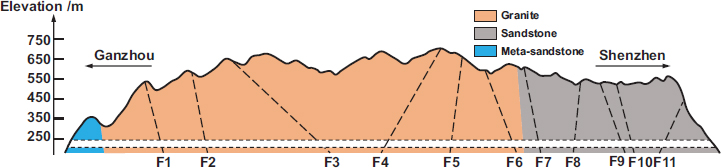
The surrounding rocks of Longnan Tunnel are dominated by the Mid-Cambrian system, Gaotan Group (ϵ2gt) metamorphic sandstone, Yanshan Period () granite, and Devonian system Middle Devonian series Laohuao Group (D2l) sandstone, as shown in Fig. (2). Longnan tunnel is divided into the following grades of surrounding rock: II, III, IV, V, and VI, and the mileage of each grade of surrounding rock is shown in Table 1. Among them, the Grade III surrounding rock was excavated by the bench method, with a single cycle feed of 2.4m and a step length of 5~8m. The Grade IV surrounding rock was excavated by the three-bench method, with a single cycle feed of 2.0m and a step length of 5~10m. The Grade V surrounding rock was excavated by the three-step temporary inverted arch method, the six-step CD method, and the open excavation method (entrance and exit position) according to the actual situation. It can be observed that the bench method is still one of the main methods for tunneling large cross-sections.
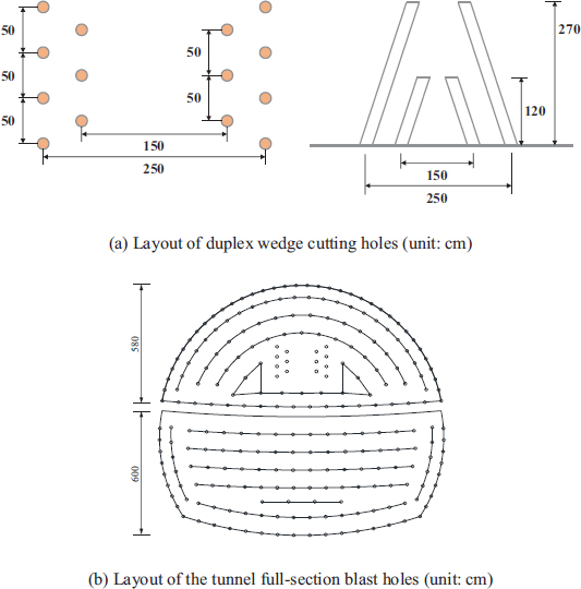
Taking the blasting excavation of Grade III surrounding rock as an example, the layout of the tunnel cross-section borehole for the Longnan tunnel excavated by bench blasting method is shown in Fig. (3). By using the smooth blasting method, periphery hole spacing was found to be 55cm, and the thickness of the smooth blasting layer was 60cm. The upper bench was cut using the duplex wedge cutting method, and the secondary cut hole was over 30cm deep. The relief hole, buffer hole, and perimeter hole were all over 20cm deep, and the bottom hole was over 25cm deep. The arrangement of holes and charge parameters are shown in Table 2.
3. ACOUSTIC TESTS
Theory and practice show that the wave velocity variation and the damage characteristics of the surrounding rock are closely related [8-12]. The RSM-SY7 non-metallic ultrasonic detector was developed by Wuhan Sinorock Technology Co., Ltd and has been widely used in rock longitudinal wave velocity testing and acoustic integrity testing of foundation piles. In this study, the RSM-SY7 non-metallic ultrasonic detector was used to perform acoustic testing on the surrounding blasted rock of the Longnan tunnel using the Grade III rock step method.
3.1. Test Scheme
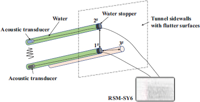
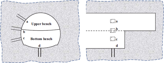
The cross-hole acoustic method is the most commonly used method for acoustic testing of the surrounding rock. Acoustic waves are emitted in one borehole of the surrounding rock, and acoustic signals are received in another adjacent borehole. Information on the first arrival time and first wave amplitude and frequency of the transmitted acoustic waves are extracted, and the wave velocity of the surrounding rock between the two boreholes is determined by analytical calculations. In this study, the cross-hole acoustic method was used for acoustic testing of the retained rock mass after tunnel blasting excavation. Hole #1 was drilled at a depth of 500 cm on a flat surface of the tunnel sidewall. Holes 2# and 3# were kept parallel to 1#, and the distance between the center of the holes was 50 cm. The three holes formed an isosceles right triangle, and the residue in the holes was flushed away after the holes were formed to avoid any influence on the test results. During the test, the transmitting and receiving transducers were moved 20 cm toward the hole opening for each side of the sound wave obtained from the bottom of the hole at the beginning of the test. The field layout of the cross-hole sound wave method is shown in Fig. (4).
In order to obtain the damage characteristics of the surrounding rock of the bench method, blasting excavation and acoustic tests were conducted on different parts of the surrounding rock after tunnel blasting, and the test points are shown in Fig. (5). The test holes are distributed in four parts: A, B, C and D, corresponding to the shoulder part of the tunnel arch, the waist part of the tunnel arch (also the foot part of the upper bench), the foot part of the tunnel arch, and the bottom of the elevated arch of the tunnel.
3.2. Acoustic Test Results
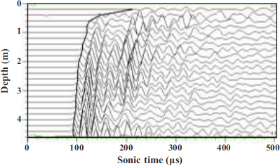
Acoustic testing was performed on the surrounding rock after blasting in the Longnan tunnel. A typical acoustic wave train is shown in Fig. (2). For a part of the test acoustic wave train map, the borehole (depth of 0 m) of the surrounding rock acoustic wave velocity due to the test process of disturbance and difficult-to-fill water coupling and other reasons cannot be measured. In the acoustic waveform, 0 μs is the moment when the transmitting transducer emits the electrical signal, and the starting moment is the moment when the receiving transducer receives the electrical signal, and the difference between the two moments is the duration of the acoustic wave propagation in the surrounding rock medium. As shown in Fig. (6), the waveform onset moments at each test depth were found to be connected, and it has been observed that the sound time within 1 m near the excavation surface was significantly longer than that at the bottom of the test hole.
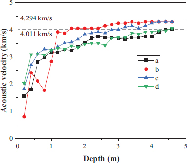
After automatic computer reading, the distribution of acoustic wave velocity of each part was calculated and plotted, as shown in Fig. (7). It has been observed that the acoustic wave velocity of the surrounding rock far from the excavation face was larger and relatively stable, and the acoustic wave velocity of the surrounding rock decreased to different degrees when it was closer to the excavation face, in which the maximum value of acoustic wave velocity of surrounding rock in parts A and D was reported to be 4.011 km/s, and the maximum value of acoustic wave velocity of surrounding rock in parts B and C was 4.294 km/s, with a difference of 6.59%, indicating that the surrounding rock was heterogeneous.
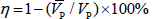
According to the reference information given in the “SL 47-2020 Technical Code for Rock Foundation Excavation of Hydraulic Structures”, whether blasting damage occurs in the rock body can be judged according to the rate of change of wave velocity η before and after blasting in the same part, and the rate of change η is calculated as:
 |
(1) |
Formula:  is the wave velocity before blasting, and VP is the wave velocity after blasting. When η is ≤ 10%, there is no damage or little damage to the rock mass; when 10% < η ≤ 15%, the rock mass is slightly damaged; when η is > 15%, the rock mass is damaged.
If the observation is made only after blasting, the wave velocity in the original state near the observation site can be used as the wave velocity before blasting, or it can be determined from the changing trend and characteristics of the observation data. In this test, according to the distribution law of acoustic wave velocity with the depth of surrounding rock, we determined the pre-burst wave velocity of 4.011 km/s in parts A and D and 4.294 km/s in parts B and C.
3.3. Relationship between Damage Variable and Acoustic Wave Velocity
In rock engineering, the damage variable D is often used to characterize the attenuation of mechanical properties of a rock mass after disturbance, and the effective modulus of elasticity of material will decay linearly after damage, as shown in Formula (2).
 |
(2) |
Formula:  and Ed are the dynamic modulus of elasticity before and after the damage, respectively.
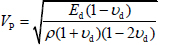
In engineering practice, the damage variable of the rock mass can be characterized by the change in acoustic wave velocity. According to fluctuation theory, the wave velocity of a wave propagating in a continuous, homogeneous, isotropic elastic medium can be expressed as:
 |
(3) |
Formula: VP is the longitudinal wave velocity of the rock mass, ρ is the density of the rock mass, and νd is the dynamic Poisson's ratio.
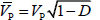
From formula (3), it can be seen that the propagation of elastic waves in the medium is only related to the medium density ρ and its dynamic deformation parameters Ed and νd. Assuming that the dynamic Poisson's ratio νd and the density ρ of the rock mass remain constant before and after blasting, substituting formula (2) into formula (3) yields:
 |
(4) |
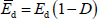
Formula: is the longitudinal wave velocity after blasting.
From formula (4), the relationship between the damage variable of the rock and the acoustic wave velocity of the rock before and after the damage can be obtained as follows:
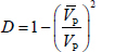 |
(5) |
Using equation (5), the threshold value of the surrounding rock affected by blasting was calculated, and the damage variable was found to be 0.19 for a wave velocity change rate of 10%.
3.4. Relationship between Damage Variable and Damage Depth
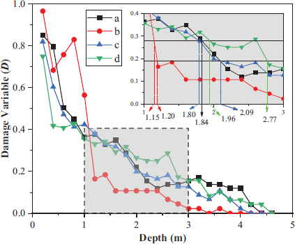
Fig. (8) shows the distribution pattern of different parts. Using the damage variable of 0.19 as the rock damage standard, the damage depths of the four test sites were 2.09 m at a, 1.20 m at b, 2.09 m at c, and 2.77 m at d. Using the damage variable of 0.28 as the rock damage, the damage depths of the four test sites were 1.84 m at a, 1.15 m at b, 1.80 m at c, and 1.96 m at d. Under the two standards, the depth of damage to the surrounding rock at the bottom of the tunnel was found to be the largest, followed by the arch waist of the two benches, and the depth of damage at the intersection of the two benches was the smallest. The depth of damage was determined by the two standards, the largest difference at d, and the remaining three differences were within 15%. For safety, the 0.19 damage variable was used as the damage standard for the rock mass in the subsequent analysis.
Further analysis was performed on the distribution curve characteristics of the damage variable by focusing on the depth of surrounding rock in each part of the tunnel section. It has been found that the damage variable of rock at the intersection of two benches at the excavation face was the largest at b, which exceeded 90%. Here, the wave velocity of the surrounding rock was only 797 m/s. Moreover, the density of rock mass hardly changed, and the wave impedance of the surrounding rock at the excavation face became smaller. The wave impedance matching between rock masses with different damage variables was found to be poor. As it was difficult for the blasting stress wave to propagate further through the severely damaged rock mass, the damage depth at this place was the smallest. Other parts of the excavation face with the damage variable were relatively small, and the wave impedance of the rock at different depths was better matched, which was conducive to the propagation of blasting stress waves. Hence, the depth of damage was relatively large.
4. NUMERICAL SIMULATION OF SURROUNDING ROCK DAMAGE
In order to further study the damage distribution characteristics of tunnel blasting excavation surrounding rock, the numerical simulation of the damage situation of the Longnan tunnel using the bench blasting excavation surrounding rock was carried out. In this study, LS-DYNA finite element software was used for modeling. LS-DYNA is the flagship product of LSTC, which adopts the dynamic display center difference method and is usually used to simulate large deformation dynamic response mathematical problems, such as high-velocity impact, blasting impact, and other structural dynamic problems.
|
ρ (kg/m3) |
E (GPa) |
μ |
Rt (MPa) |
Rc (MPa) |
|---|---|---|---|---|
| 2500 | 38 | 0.25 | 1.17 | 12 |
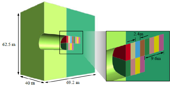
4.1. Numerical Model
LS-DYNA was used to establish the numerical model of tunnel blasting excavation [13-15]. In order to save computational resources, a 1/2 model was established, the symmetry plane of the model was set with normal displacement constraints, and the remaining five planes were set as transmission boundaries to simulate the infinite boundaries of the actual project. The model height, width, and thickness were 62.5 m, 40 m, and 69.2 m, respectively, as shown in Fig. (9).
The intrinsic model of the rock mass was used with a statistical damage softening model based on the Weibull distribution [16]. The physical and mechanical parameters of the rock masses used are shown in Table 3.
Table 3: ρ is the density of the rock mass, E is the elastic modulus, μ is the Poisson's ratio, Rt is the tensile strength, and Rc is the compressive strength.
The large number of blast holes is very complicated to model. Previous studies have shown [17, 18] that the use of equivalent blast loads to simulate the dynamic effects of the surrounding rock under the action of tunnel blasting can meet the required accuracy in engineering. In this study, a triangular load [19] was used as the equivalent blasting load, which was applied to the excavation boundary of the tunnel. The rise time of the triangular load, the time of positive pressure action, and the calculation of the peak load were already discussed in the literature [20]. The restart analysis function of LS-DYNA was used to realize the cyclic tunneling.
4.2. Tunnel Surrounding Rock Damage Characteristics
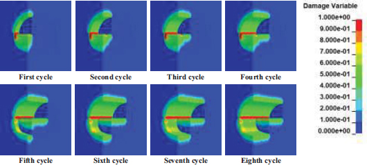
The numerical simulation of eight cycles of tunnel surrounding rock damage distribution cloud atlas is shown in Fig. (10). It can be seen that the surrounding rock damage caused by each cycle of blasting will be superimposed on the previous cycle of surrounding rock damage, resulting in deeper damage or greater damage to the surrounding rock. Overall, the damage to the surrounding rock at the arch footing of the upper bench is the most serious after the bench blasting excavation.
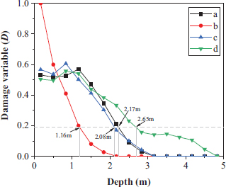
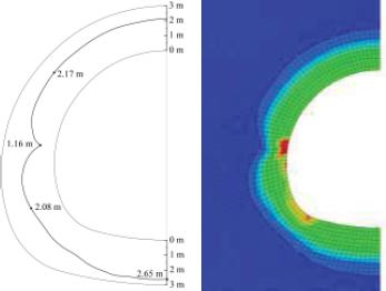
The distribution of the damage variable with the depth of the surrounding rock at the four locations that are statistically the same as the site acoustic test site is shown in Fig. (11). It has been observed that when the damage variable is 0.19, corresponding to A, B, C, and D for damage depths of 2.17m, 1.16m, 2.08m and 2.65m, respectively, and the numerical simulation of the surrounding rock damage depth and acoustic damage variable assessment of the damage depth are close to each other, the error is within 5%. As for the distribution characteristics of the surrounding rock damage, due to the non-homogeneity of the tunnel surrounding rock, the distribution characteristics of the damage variables obtained from numerical simulation and the distribution characteristics of the damage variable obtained from acoustic testing are somewhat different, but the overall distribution law is the same. When the damage at the excavation surface is serious, the damage depth of the corresponding part is small, such as the arch footing part of the upper bench; when the damage is relatively minor, the damage depth of the corresponding part is large, such as the inverted arch part. Compared to the above numerical simulation results and acoustic test results, the numerical simulation results are reliable.
5. TUNNEL ANCHORAGE PARAMETERS SELECTION
The selection of parameters for the initial tunnel support is usually based on the engineering analogy method, and the Code for Rockbolt Support Technical of Railway Tunnel (Q ∕ CR 9248-2020) [21] gives the design parameters for composite lining anchor support in single-line and double-line railroad tunnels at different envelope rock levels based on the engineering analogy method. The length of the anchor rod in arch of Grade III surrounding rock is 3m. Technical code for the engineering of ground anchorages and shotcrete support (GB50086-2015) [22] gives the preliminary design parameters for the anchor spray support parameters for tunnels based on the engineering analogy method. The length of anchor rods in Grade III rock tunnel with an excavation span of 10 m ~ 15 m is 3.5 m ~ 4.5 m. The specification also states that in tunnels and underground works, the free section of anchor rods resisting locally unstable blocks below the hance should pass through the slip surface by not less than 1.5m.
A typical cross-section of the damage distribution of tunnel surrounding rock was selected, and the damage depth distribution of the tunnel surrounding rock was identified, as shown in Fig. (12). It has been observed that the minimum depth of tunnel damage was 1.16m, located in the hance of the tunnel, corresponding to the arch footing of the upper bench. The deepest depth of damage to the surrounding rock was 2.65m, located in the inverted arch part of the tunnel. In the tunnel arch roof, the depth of damage to the surrounding rock was more uniform, i.e., about 2.17m. Near the arch footing in the full section, the depth of damage was about 2.08m.
Based on the recommended length of anchor rods given by the engineering analogy method in the above specification, the free section of the anchor rod should cross the slip surface by not less than 1.5 m. Considering the general location of the anchor rod arrangement (side walls and vault), it was determined that the length of the initial supporting bolt for Grade III surrounding rock in Longnan tunnel should be 3.5 m ~ 4 m.
CONCLUSION
In this study, based on the acoustic test results of tunnel envelope rock excavated by the blasting step method of Grade III envelope rock in Longnan tunnel, combined with numerical simulation means, the damage characteristics of tunnel blasting envelope rock were analyzed, and the initial tunnel support parameters were further proposed. The main findings are as follows:
(1) By acoustic wave velocity reduction rate, the depth of damage to the surrounding rock of the Longnan Tunnel III step excavation tunnel was determined by using a damage variable of 0.19 as the damage criterion, spandrel of the surrounding rock damage depth of 2.09 m, hance (upper bench arch footing) damage depth of 1.20 m, arch footing damage depth of 2.09 m, and damage depth of 2.77 m at the bottom of the inverted arch.
(2) According to the damage variable distribution characteristics of the tunnel surrounding rock, it could be concluded that when the damage at the tunnel excavation surface was serious, the damage depth of the corresponding part was small, such as the arch footing part of the upper bench; when the damage was relatively minor, the damage depth of the corresponding part was large, such as the inverted arch part. Therefore, the charge could be strengthened appropriately to avoid under-excavation of the arch footing.
(3) The damage depth of the surrounding rock obtained by numerical simulation was within 5% error, which was close to the damage depth of the surrounding rock obtained by acoustic testing. Based on the characteristics of the depth distribution of damage to the surrounding rock in the tunnel section, the length of the initial supporting bolt for the Grade III surrounding rock in Longnan Tunnel was determined to be 3.5 m ~ 4 m according to engineering analogies and relevant specifications.
LIST OF ABBREVIATIONS
| BIDZ | = Blast-induced damage zone |
| 3DEC | = Discrete element software |
| LSTC | = Livermore software |
CONSENT FOR PUBLICATION
Not applicable.
AVAILABILITY OF DATA AND MATERIALS
The data involved in this study are available in the article.
FUNDING
This work was supported by the National Natural Science Foundation of China (NSFC, grant number 41972286).
CONFLICT OF INTEREST
Dr. Chuanbo Zhou is on the editorial advisory board of the journal of The Open Civil Engineering Journal.
ACKNOWLEDGEMENTS
Declared none.

