All published articles of this journal are available on ScienceDirect.

Influence of Spring Stiffness on the Loading Speed of the Falling Weight Deflectometer (FWD) in Bearing Capacity Evaluation of Cement Concrete Pavement
Abstract
Introduction:
The bearing capacity evaluation of cement concrete runway pavement is one of the most important contents in the airfield operation. Among the methods for estimating bearing capacity, the Falling Weight Deflectometer (FWD) is the most widely used method because it does not damage the pavement structure and spends so much time. The equipment for evaluation should have suitable parameters, such as. magnitude and loading speed, to the actual operating loads.
Aims and Objectives:
Currently, the equipment to assess the bearing capacity of cement concrete pavements of highways and airports by falling weight has been widely used in the world and is being applied in Vietnam. The loading system consists of a falling block through a spring system acting on the pressure plate under the pavement with a certain falling height. In particular, the spring system plays an important role in controlling the speed of the load on the pavement. In Vietnam, the test standards (Industry Standard 22TCN335-06, Vietnamese Standard TCVN 11365-2016) for assessing the pavement bearing capacity by FWD equipment do not specify the selection of spring stiffness corresponding to different operating speeds of the vehicle. Therefore, it is difficult to use the equipment for pavements with operating speeds different from the standard.
In this paper, we study the effect of spring stiffness on the loading speed when considering different loading speeds corresponding to different speeds of vehicles moving in reality. This research is only limited to laboratory experiments. This study aims to determine the dependence of the loading magnitude and loading time on the damping spring stiffness of the dynamic loading equipment, that is, used as a basis for choosing the appropriate damping stiffness of FWD corresponding to actual vehicles.
Methods:
Among the methods for estimating the bearing capacity, the Falling Weight Deflectometer (FWD) is the most widely used method as it does not cause any damage to the pavement structure and spends much time. The equipment for evaluation should have suitable parameters, such as magnitude and loading speed, to the actual operating loads.
Results:
This paper presents the results of experimental research that determines the influence of the damping spring stiffness on the loading speed of the dynamic loading equipment on the model of the concrete slab in the laboratory.
Conclusion:
Based on the comparison of the FWD loading speed when using 02 damping springs with different stiffness, we propose the basis for choosing the damping system that conforms to the evaluation needs of different types of vehicles.
1. INTRODUCTION
In the calculation of cement concrete slabs for automobile and airfield pavements, in the standards of many countries as well as in Vietnam, the structure is considered subjected to static loads, and then the slab is usually analyzed based on the model of the plate on the elastic foundation [1-5]. Such an assumption is to simplify the calculation and ensure the pavement is working in safe conditions. In fact, the wheel load acting on the road surface the dynamic load. Furthermore, the foundation material is a typical three-phase material, i.e., solid, liquid, and gaseous phases [6-9]. The response of such material to dynamic loads is different from that under static loads [10-13]. Many studies have shown that under the effect of dynamic loads, the response of the pavement structure is delayed in terms of deformation. This is known as the viscous characteristic of the pavement under dynamic load. Thus, when analyzing the pavement structure based on a dynamic point of view, the pavement structure could be considered as a viscoelastic material.
The FWD (Falling Weight Deflectometer)/HWD (High Weight Deflection) device is widely used in the bearing capacity evaluation of the existing pavement [8, 14-19]. Being a device based on the pulsating load, loading speed reflects the speed of the real load, which is the wheel load of vehicles. Therefore, calibrating the load rate of the equipment to match the service load rate is important for each specific pavement load assessment project.
This paper aims at studying the influence of spring stiffness, which is a component of dynamic loading equipment, on the loading speed of FWD equipment based on laboratory experiments with pavement models and homemade equipment.
2. MATERIALS AND METHODS
2.1. The Theoretical basis for Determining the Influence of Spring Stiffness by Experimentation
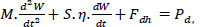
When evaluating the bearing capacity of cement concrete slabs by FWD equipment, the concrete slab is subjected to dynamic load. The general equilibrium differential Eq. of the slab is written as follows [2, 12, 13]:
 |
(1) |
where: Pd is dynamic load, kN;
 is the vertical acceleration of the concrete slab, m/s2;
M is the oscillating mass of the concrete slab in the deflection basin, kg;
 is the oscillating speed of the concrete slab, m/s;
S is the area of the projection of the pavement deflection on the horizontal plane (Dcv);
η is the viscous coefficient of the foundation (N.s/cm3);
Fdh is the reaction force of the foundation with the slab [16],
Fdh = C.Vd, with Vd as the entire dynamic deflection basin volume due to dynamic load.
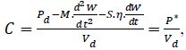
From Eq. (1), one obtains the formula for determining the dynamic foundation coefficient as follows:
 |
(2) |
Eq. (2) shows that one can calculate the dynamic foundation coefficient if the volume of the deflection basin is determined that can be obtained from the field test results.
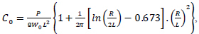
Instead of using a large number of sensors to accurately determine the volume of the pavement deflection, we can use the AREA Based Method with the sensors placed at specified distances from the center of the concrete slab to determine the elastic characteristics of the slab. According to this method, one uses the following formula proposed by Westergaad to determine the dynamic foundation coefficient [12]:
 |
(3) |
where: Pd is the dynamic load, kN;
W0 is the deflection measured at the center of the plate, mm (inch);
R is the radius of the plate, m;
L is the radius of relative stiffness determined by AREA Based Method [10, 20], according to the formula:
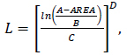 |
(4) |
where the constants are chosen as follows: A= 36; B = 1812.279; C= -2.559 and D =4.387 [10];
 |
(5) |
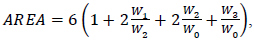
In Eq. (5), W0, W1, W2, and W3 are the deflections at the points with a distance of 0, 30, 60, and 90 cm from the center of the pressing plate respectively, and at the moment that the load reaches the maximum value [10, 14, 20].
If the parameters such as elastic characteristics L, foundation coefficient C, and concrete slab thickness h are identified, we can determine straightforward parameters: elastic modulus E, flexural tensile strength Rku, and the bearing capacity of the pavement as presented in [2, 12, 13].
2.2. Choosing the Damping Stiffness of the Evaluation Equipment (FWD)
The affected time of the load depends on the damping characteristics of the test spring that needs to be conformal with the vehicle speed. Therefore, through the selection of springs with different damping stiffnesses, we will obtain different experimental models corresponding to different velocities of the vehicle.
The dependence of the affected time of load on the damping characteristic according to the relationship below [2, 21]:
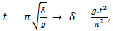 |
(6) |
where: δ is degree of damping, cm;
t is the affected time of load, s;
g is gravity acceleration, g is 981 cm/s2; π = 3.14;
The relationship between the vehicle velocity and the affected time of the load according to [2, 13, 22]:
 |
(7) |
Where: Dcv is the diameter of the deflection basin (cm), which can consider that the value of the deflection basin is five times of the slab elastic characteristic, i.e., DCV = 5L [2, 13];
V is the vehicle velocity in the calculation, m/s.
From (6) and (7), we obtain the formula for choosing the damping stiffness according to the calculation of vehicle velocity:
 |
(8) |
It can be seen from Eq. (8) that the affected duration of the load depends only on the stiffness characteristic of the damping system, not on the magnitude of the load. When determining the affected time of the load, we can determine the stiffness coefficient through the dynamic deflection diameter from Eq. (8), and thereby the loading velocity in the test. Therefore, in order to experiment with the bearing capacity of the pavement when knowing the operation vehicle, from the corresponding vehicle velocity value, we can choose the suitable damping stiffness of the spring of the dynamic testing equipment.
2.3. Experimental Research in the Laboratory
2.3.1. Experimental Model
The experimental model is a cement concrete slab in the laboratory at Le Quy Don Technical University. The model can be described as follows:
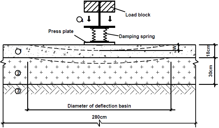
The dimension of the concrete slab is 280 cm x 280 cm; the thickness is 18 cm;
The foundation is compacted sand with a tightness of 0.95 with a thickness of 30 cm placed on a compacted natural subgrade with a tightness of 0.90.
The concrete pavement structure model in our laboratory is simulated in Fig. (1).
1. Cement concrete slab with a thickness is 18cm; 2. Compacted sand with a thickness is 30cm placed on natural subgrade; 3. Natural subgrade; 4. Dynamic loading equipment
2.3.2. Experimental Equipment
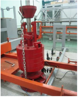
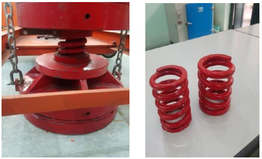
Combination of dynamic loading: This equipment includes a combination of falling devices (falling weight system, shock absorber spring), a device frame, and a load plate with a diameter of 33cm (Fig. 2). In the middle of the base of the plate, there is a hole where the dynamic pressure gauge PCB, model 202B PIEZOTRONICS, is located.
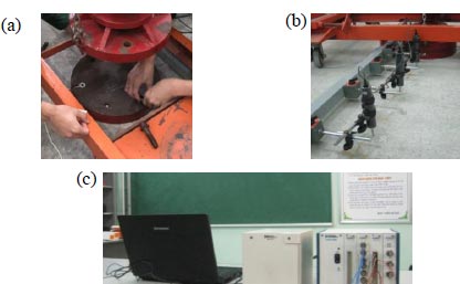
(a) PCB Piezotronics dynamic pressure gauge model 202B; (b) Dynamic transposition gauge CDP50; (c) SXI 1000DC/ National Instrument Oscilloscope with LabVIEW Signal Express software.
2.3.3. Dynamic Deflection Gauge System of the Pavement Model
Dynamic deflection measuring device CDP50, is arranged synchronously with the magnetic soles and along the jig at positions from the center of the plate about 0, 30, 60, and 90 cm.
2.3.4. Data Acquisition and Processing Equipment
Dynamic experimental data were acquired and analyzed by the US SXI 1000DC/NATIONAL INSTRUMENT oscillo- scope and processed by LabVIEW SignalExpress 3.0 software.
2.3.5. Description of Experimental Content
When loading is performed, the magnitude of the dynamic load will be changed through the falling height of the load block. When the moving load block slides through the locking pin, the entire load block (consisting of 5 component metal blocks) will fall. The load is transmitted through the damping spring system to reduce the impact on the pavement.
Three types of damping spring systems with different stiffness are used for determining different affected velocity magnitudes of the load (Fig. 4).
The magnitude of the load is determined through three dynamic pressure gauges US PIEZOTRONICS model 202B PCB, while the dynamic deflection is determined by four dynamic transposition gauges CDP50. Measurement data were recorded as a file with extension *.txt by LabVIEW SignalExpress 3.0 software through oscilloscope SXI 1000DC/ National Instrument.
3. RESULTS AND DISCUSSION
In this study, we used a concrete slab model, and laboratory equipment was fixed. According to some studies that have been done with this concrete slab, its bearing capacity is about 9 tons, so the test load evaluated by the FWD device that we studied here was selected to be less than 6 tons for the safety of this slab.
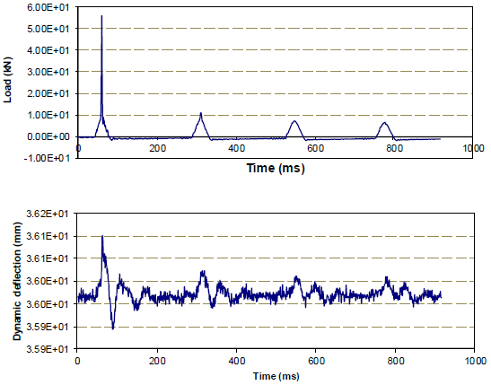
Experimental tests were conducted with two types of damping springs and the obtained results of dynamic load and dynamic transposition are presented in Fig. (5).
To conveniently determine the affected duration of the load, the data will be extracted for a certain number of measurement points around the maximum point based on a developed Matlab code.
The load results of a calculation piece for the first damping spring system are illustrated in Fig. (6), and thereby one can determine the affected time of the load for each test.
The results of determining the magnitude of the load with different load levels are shown in the following Fig. (6) and Table 1.
Based on the measurements presented above, the affected duration of the load is determined through extreme points of the graph (Fig. 7). Once the affected duration is determined, one can calculate the spring stiffness.
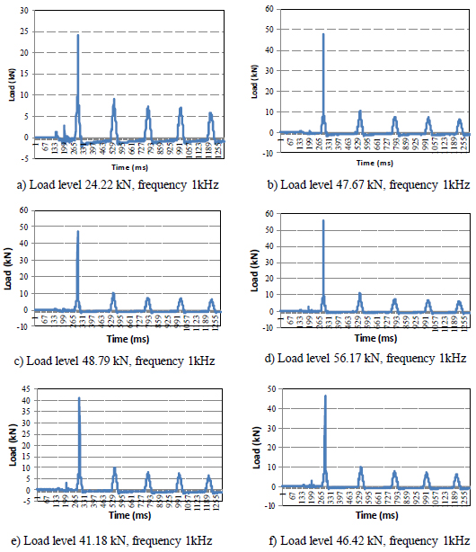
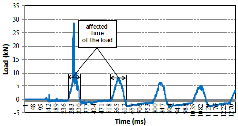
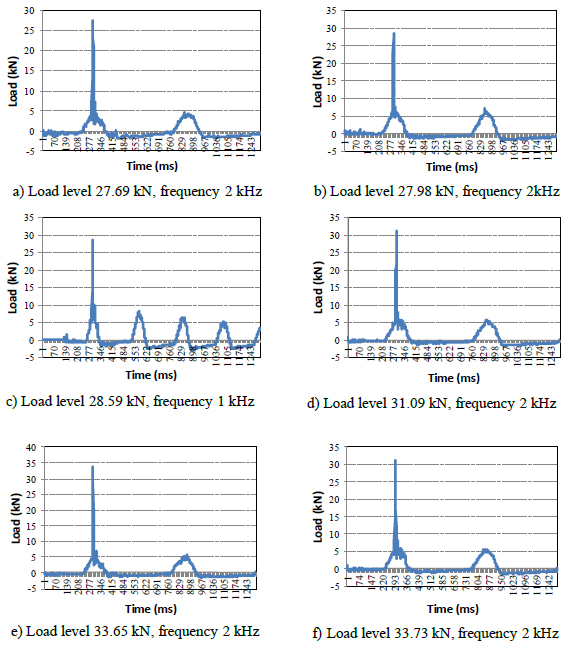
Table 2.
| Sequence | Load (kN) | Measurement Frequency (Hz) | Order of the First Pick | Order of Pick Points Later | Affected Time (ms) | Damping Characteristic δ (cm) | Calculation Speed v (m/s) |
|---|---|---|---|---|---|---|---|
| 1 | 28.59 | 1000 | 262 | 342 | 80 | 0.64 | 36.94 |
| 2 | 27.98 | 2000 | 214 | 378 | 82 | 0.67 | 36.04 |
| 3 | 31.09 | 2000 | 226 | 382 | 78 | 0.61 | 37.88 |
| 4 | 32.29 | 2000 | 229 | 387 | 79 | 0.62 | 37.41 |
| 5 | 33.65 | 2000 | 222 | 380 | 79 | 0.62 | 37.41 |
| 6 | 32.30 | 2000 | 214 | 378 | 82 | 0.67 | 36.04 |
| Average | - | - | - | - | 80 | 0.64 | 36.95 |
Relying on the graph, one can determine the affected duration of the load according to the number of pick points and the measured frequency. Thereafter, the damping character- istics of the spring system are determined from formula (6), and the loading velocity corresponds to the spring stiffness according to formula (8) when the elastic characteristic of the slab is known, precisely here L = 59.1 cm [11].
Similar to the above procedure, one obtains the results of dynamic load measurement when using the second damping spring with two sampling frequencies which are 1 kHz and 2 kHz as presented in Fig. (8).
We have the results of the affected load time for the second spring as summarized in Table 2. It is noted that, when the frequency is equal to 2kHz, the distance between two pick points is equivalent to a period of 0.5 ms.
It is noted again that the spring stiffness and loading speed do not depend on the magnitude of the affected dynamic load (through adjusting the drop height of the load block). The results also show that the greater the spring stiffness (the smaller damping), the greater speed of affection load.
CONCLUSION AND RECOMMENDATIONS
In this study, a series of tests of FWD relied on the experimental model in the laboratory was conducted to simulate the dynamic loading of vehicles on the rigid pavement and the following main results can be made.
The affected load time does not depend on the falling height of the load block, but only on the damping spring stiffness characteristics. The greater the spring stiffness (the smaller damping), the greater speed of affection load.
The results of the experimental dynamic load tests showed that the vehicle speed takes the average value of 55.95 m/s (=201.4 km/h) in six times measurements when using the first spring. This value is equivalent to the speed of medium-range aircraft during takeoff and landing or the start of the braking stage. With respect to the second spring, the speed value of 36.95 m/s (133 km/h) is equivalent to the short-range aircraft speed when performing the run-up stage or in the middle of the braking stage. Therefore, it is possible to choose the appropriate loading speed for each vehicle or aircraft when changing springs of different stiffness.
These test results in this study could be considered the basis for completing the theory of assessment of pavement bearing capacity when applying FWD equipment in Vietnam.
LIST OF ABBREVIATIONS
| FWD | = Falling Weight Deflectometer |
| HWD | = High Weight Deflection |
CONSENT FOR PUBLICATION
Not applicable.
AVAILABILITY OF DATA AND MATERIALS
Not applicable.
FUNDING
None.
CONFLICT OF INTEREST
The authors declare no conflict of interest financial or otherwise.
ACKNOWLEDGEMENTS
This study was supported by the Bridges, Roads, and Airports laboratory, a specialized laboratory at Le Quy Dong technical university, in Hanoi City, Vietnam. The authors are very grateful to the experts for their constructive comments.

