All published articles of this journal are available on ScienceDirect.

Engineering Characteristics at Early Age of Cemented Silica Fume Paste for Peat Compaction Grouting
Abstract
Introduction
Cemented Silica Fume Paste (CSFP) is currently being investigated for compaction grouting material to improve peat ground engineering properties. The CSFP is made in the laboratory using a proportional mixture of silica fume, cement binder, and tap water. The silica fume material is a byproduct of the metal processing industry, which critically requires a better alternative utilization in the near future in order to cut the storage cost and minimize the environmental impact.
Aims
This paper aims to present preliminary results on the engineering characteristics of CSFP at an early age through a series of rheological and strength tests. A general observation of the physical properties and microstructure of CSFP is also presented.
Methods
The CSFP specimens with cement binder range from 0% to 30% with the increment of 5% and Water-to-Solid (W/S) ratio ranges from 0.8, 0.9 and 1.0 were prepared and tested. A series of rheology test and Unconfined Compressive Strength (UCS) tests were carried out for the CSFP specimens at an early age. The data were analyzed statistically and mathematical formulation is presented.
Results
The results indicate that CSFP mixtures behave as pseudoplastic or shear thinning fluid, where the shear stress and viscosity depend highly on the shear rates. The higher the shear rates, the higher the shear stress and the lower the viscosity. Curve fitting showed that the best relationship between shear stress and shear rate is the power law function (Ostwald–de Waele relationship). Statistical parameters, k, n, R2 of the power law functions are reported. There was no good correlation found between the power law function statistical parameters and the cement content. The UCS tests showed that the shear strength increases with the amount of cement content. The actual W/S reduces as the cement content increases, which is attributed to the cement hydration.
Conclusion
The CSFP mixtures were found to be a pseudoplastic or shear thinning fluid at an early age that provides an advantage during the material injection on the ground. Cemented Silica Fume Paste can be potentially used as compaction grout to improve peat. The current findings provide a better understanding of the CSFP characteristics and to better design CSFP to be injected into peat ground.
1. INTRODUCTION
Infrastructure development often requires expansion into peat areas due to the decline in areas with good soil conditions. Construction in peat grounds requires better methods in order to sustain load from the above infrastructure such as road embankment. Several construction methods have been proposed and a few of them have been practically implemented [1, 2]. In general, the construction methods for peat grounds can be categorized as the following: removal and replacement, staging and filling technique, expediting consolidation, load transferring, and peat mixing. The best choice to apply depends on the peat properties, the ground condition, the type of construction, the availability of material and facilities, and cost.
On the other hand, industrial development in the metal processing industry has been exponentially increasing due to the technology demands. Metal processing generates by-products (wastes) that require either a proper storage or an appropriate utilization in order to reduce storage cost and to minimize the impact to the environment, respectively. As the by-product accumulates over time, the storage cost will increase and the impact on the environment will potentially increase as well. Therefore, the accumulation of the byproduct will eventually necessitate the appropriate utilization to be implemented.
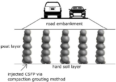
Cemented Silica Fume Paste (CSFP) is a newly proposed material to be used as one of the construction methods to increase the strength and compressibility of peat. The material is similar to paste-fill which has been successfully and popularly used for the last two decades in order to stabilize underground stope [3, 4]. The CSFP will be used as a grout material by injecting it into the peat ground in order to densify the peat from within (the inside) such that the bearing capacity of the peat increases that suffices to support the external load from the road embankment. Such densification process will reduce the void within peat, and will increase the normal stress and the shear stress of the peat. Injecting the grout material into the soil is generally called compaction grouting [5, 6]. Models showed that compaction grouting increases mechanical properties of soil, such as dry unit weight, apparent cohesion, friction angle, and dilatancy [7, 8]. It has been successfully used to improve the characteristics of the sand to clay soils, such as densification, reducing liquefaction potential, increasing pullout capacity in soil nailing, etc. [9-11]. However, the study on the application of compaction grouting in peat is lacking. It is expected that compaction grouting solves not only the problem of peat but also reduces the accumulation of industrial by-product at the same time. Fig. (1) illustrates how the CSFP will be used to support peat as a road embankment foundation.
The silica fume has been so far utilized and marketed commercially as an additive to produce and improve high strength concrete [12, 13]. The silica fume assists in pozzolanic reaction and acts as a pore filler to reduce the void and permeability of concrete owing to its extremely small size particles [14]. However, the utilization rate for such an application is much smaller than the production rate of the silica fume. The utilization of some other applications is required to balance or to surpass the production rate.
This paper presents the preliminary results on the engineering characteristics of CSFP, which focuses on rheology and strength behaviour at early age. The rheology and strength behaviour at early age are important aspects to be understood for the injectability (flowability) of the CSFP during its application. The finding is useful for engineers and academics to better understand the CSFP engineering behaviour as an alternative improvement of peat ground.
2. MATERIALS AND METHODS
2.1. Silica Fume
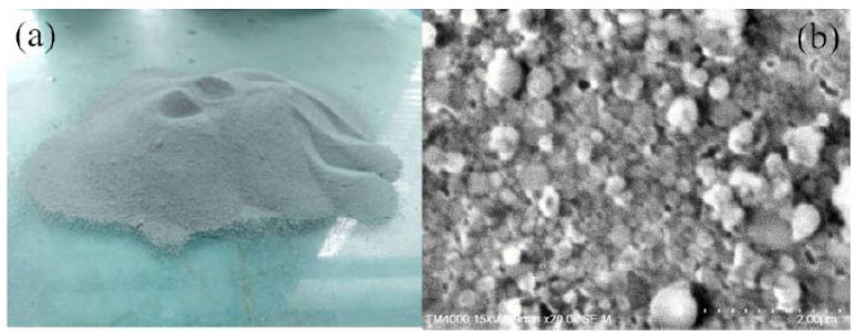
The silica fume is sourced from a local ferrosilicon alloy factory. The silica fume is originally formed as dust created from burning ferrosilicon raw material, coke and silica in an electric arc furnace, which is then collected in a gas cleaning plant. The dust is filtered and contained in special plastic bags as silica fume byproduct. Fig. (2a) a shows a photograph of the dry silica fume on a glass plate. It consists of extremely fine solid particles, light grey in color and odourless. In general, the color of silica fume can range from light to dark grey, depending on the production process [15]. The moisture content of the dry silica fume sample (from the bag) is 0.82%.
Fig. (2b) shows a picture from Scanning Electron Microscope (SEM) of the silica fume sample. The particles are shown as spherical in shape with the diameter mostly less than 0.2μm. Therefore, in a dry form, the silica fume is respirable. Since the particles are extremely fine, the specific surface area reaches between 13,000 m2/kg to 30,000 m2/kg, which is much higher compared to Ordinary Portland Cement (OPS), i.e. approximately 150-430 m2/kg [16, 17]. Larger size particles (lumps) are the results of binding together with smaller ones due to moisture. Therefore, sieve analysis of silica fume from the bag might result in a larger particle size distribution if lumps are not removed.
The chemical composition of the silica fume is predominantly SiO2 that comprises 94% by weight. The other 6% consists of other chemical components, namely: Fe2O3, K2O, MgO, CaO, Na2O, Al2O3, and P2O5. The specific gravity of the solids (Gs) of the silica fume is 2.2, at which the unit weight (γ) ranges between 200–350 kg/m3, 500–650 kg/m3, 700–1000 kg/m3 and 1400 kg/m3, when it is prepared in undensified, densified, micropelletized, and slurry conditions, respectively [18]. The Gs and the γ makes the silica fume to be much lighter than normal silica sands (Gs = 2.65). The liquid limit of the silica fume is 70%. The liquid limit is an important parameter for the flowability during compaction grouting and thus determines the preparation of samples for rheology and strength testing in this study. The high liquid limit value is associated with very large specific surface area when compared to cohesive soils such as silt and clay. The larger the specific surface area, the larger amount of water is needed to make the material behave like liquid. Table 1 summarizes the physical properties of the silica fume used in this study.
| No. | Properties | Value |
|---|---|---|
| 1 | Moisture content (in bag) | 0.82% |
| 2 | Specific gravity | 2.2 |
| 3 | Average particle size (from SEM) | 0.2 μm |
| 4 | Liquid limit | 70% |
| 5 | Plastic limit | 38.2% |
| 6 | Plasticity index | 31.8% |
2.2. The Cemented Silica Fume Paste
The Cemented Silica Fume Paste (CSFP) is designed by mixing the silica fume with cement binder and tap water at appropriate proportion. The cement binder used is an Ordinary Portland Cement (OPC) sourced from Cahya Mata Sarawak that conforms with the standard requirement specified in Malaysian Standard MS EN 197-1 [19]. The CSFP is soluble in the alkali solution. The amount of water determines the consistency of the CSFP in the solution.
Table 2 lists the design mixture that was used for the rheological properties test and UCS test in the experiments. There are three variations in terms of water-to-solid (W/S) ratio by weight, i.e. 0.8, 0.9 and 1.0. Note that the term W/S is synonymous with water content. We chose the W/S ratio to avoid confusion since the mixture has two types of solids, i.e. cement and silica fume. Also, the W/S ratio is a more practical term compared to water content. The three variations of W/S ratio are all slightly above the liquid limit, to ensure that the CFSP flows in paste-like consistency. Each W/S ratio is varied with different proportions of cement content ranging from 0% to 30% with a 5% increase. Note that the cement content is calculated in the percentage (%) by weight. Since the total amount of solid is fixed, the amount of cement replaces the amount of silica fume. The variation of cement content is investigated to determine its effects on rheological properties and shear strength of cemented silica fume paste at an early age. There are a total of twenty-one (21) specimens used in the rheological properties tests and forty-two (42) specimens used to determine the shear strength by performing the Unconfined Compressive Strength (UCS) tests. For the UCS tests, each mix has two specimens. The actual W/S ratio was recalculated after each test, since the water might dissipate during the UCS specimen preparations and tests. The prepared specimens of the design mixture included the control sample with a 0% proportion of cement.
| No. | Cement Content (%) | Water to Solid (W/S) Ratio | ||
|---|---|---|---|---|
| 1 | 0 | 0.8 | 0.9 | 1.0 |
| 2 | 5 | 0.8 | 0.9 | 1.0 |
| 3 | 10 | 0.8 | 0.9 | 1.0 |
| 4 | 15 | 0.8 | 0.9 | 1.0 |
| 5 | 20 | 0.8 | 0.9 | 1.0 |
| 6 | 25 | 0.8 | 0.9 | 1.0 |
| 7 | 30 | 0.8 | 0.9 | 1.0 |
2.3. Methods
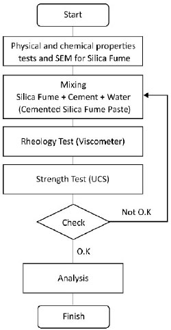
Fig. (3) shows the workflow of the experiments. Prior to rheology and strength tests, the silica fume material was physically and chemically characterized, including scanning electron microscopy. Based on the Atterberg limit values, a trial mix was conducted to determine the range of Water to Solid ratio (W/S), at which the CFSP has a good workability (flowable) consistency but is not too liquid that might cause the segregation of cement and reduction in strength.
2.4. Rheological Test
Rheological properties test was performed to determine the rheological parameters such as shear stress and viscosity of cemented silica fume paste when some of the silica fume is replaced with the cement binder (OPC). The test was conducted using a rotational viscometer instrument, HAAKE Viscotester 7 plus, in accordance with ASTM D2196 Standard Test Methods for Rheological Properties of Non-Newtonian Materials by Rotational Viscometer [20]. All test conditions and settings prescribed in the standard method were followed precisely. The tests were all performed at a controlled room temperature of 25oC. The sample of cemented silica fume paste was prepared by manually mixing the silica fume, the cement binder (OPC) and the tap water according to the design mixture (Table 2). The CSFP material components were thoroughly mixed in a glass beaker using a spatula for about 5 minutes.
The test specimen was made by pouring the sample into a 0.5 litre can to reach 25 mm from top. The specimen was shaken vigorously on the shaker for about 10 minutes. After 10 minutes, the specimen was removed from the shaker and was allowed to stand undisturbed for 60 minutes at 25oC prior to testing. The rheology test was started no later than 65 minutes after removing the can from the shaker. The instrument was placed on the adjustable stand and the viscometer was lowered to a level that would immerse the spindle to a proper depth. The spirit level was attached to level the instrument to align the specimen horizontally. The selected spindle was tilted and inserted into one side of the center of the surface of the materials, followed by attaching the spindle to the instrument. The viscometer was then lowered until the groove (immersion mark) on the shaft just touched the materials. The container was slouched in a horizontal plane until the spindle was located in approximately the center of the container so that the test would run in a region that was undisturbed by lowering the spindle. The digital viscometer was turned on and adjusted to the selected speed (unit in rotation per minute, rpm) for the materials under the test. The data was registered in the viscometer instrument at the following standard shear rates (1/s): 0, 1, 2, 4, 6, 10, 12, 20, 30, 50, 60, 100, and 200. The viscometer was allowed to run until the digital reading had stabilized and the digital viscometer gave a direct reading in Pascal and centipoises for shear stress and viscosity, respectively. The same procedure was repeated for every other design mixture.
2.5. Unconfined Compressive Strength (UCS) Test
Unconfined Compressive Strength (UCS) test was selected to determine the strength of the CSFP samples at an early age when subjected to axial stress. The axial stress was applied to a cylindrical CSFP specimen without lateral constraint (i.e., no confining pressure) while observing the axial strains corresponding to various stress levels. The axial stress at which failure in the soil specimen occurs is referred to as the UCS shear strength (Pa). The failure was defined when the axial stress dropped from the peak, followed by a physical appearance in the sample in the forms of cracks, disintegration of the material or excessive deformation. The test was conducted in accordance with ASTM D2166 “Standard Test Method for Unconfined Compressive Strength of Cohesive Soil” [21].
The test specimen was prepared in a small cylindrical PVC mold measuring 38 mm × 76 mm. The specimen was made soon after the rheology test was done. The molding and specimen extraction took about 10 minutes. After extraction, the diameter and length of the specimen was measured twice to get the average values. The specimen was placed centrally between the two loading plates of the UCS machine and the base loading plate was moved upward until the top of the specimen reached the top loading plate. The specimen was compressed vertically at a displacement rate of 1mm/min, and the readings were taken at the vertical displacement intervals, ΔL of 0.3 mm. The specimen was compressed until the specimen failed. The failed specimen was collected, weighed and placed in the oven for 24 hours for the W/S ratio calculation (i.e., moisture content).
3. RESULTS
3.1. Rheology of the CSFP
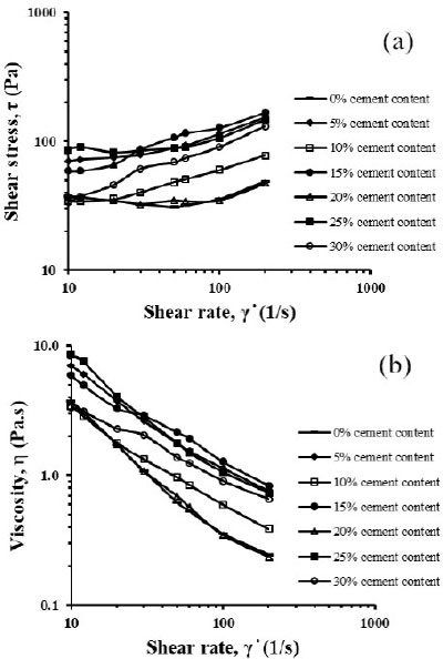
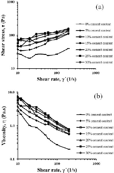
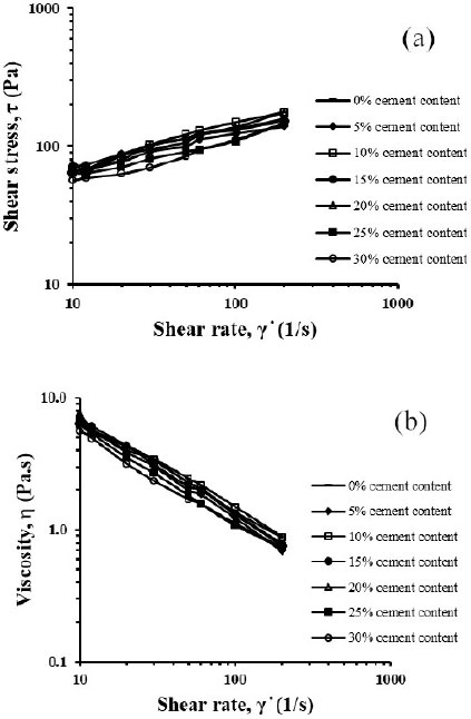
Figs. (4-6) show the observable shear stress and viscosity measurements against shear rate from the viscometer instrument reading for samples with W/S of 0.8, 0.9 and 1.0, respectively, with all variations of cement contents. The measurements are presented in log-log scale. The shear stress and viscosity start to be observable (i.e., > 0) at a shear rate of 10/s and above. The shear stress and viscosity data showed to be dependent on the shear rate. The shear stress increases as the shear rate increases, while the viscosity decreases as the shear rate increase (opposite). The same trend applies to all three samples with different W/S and cement contents.
3.2. Unconfined Compressive Strength (UCS) of the CSFP
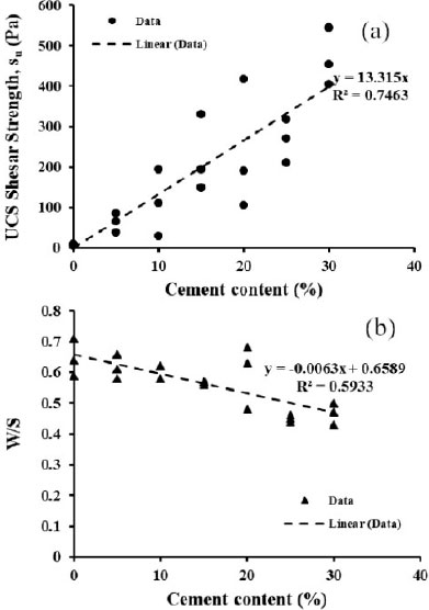
The UCS measures the ability of the specimen to sustain the axial stress without lateral confinements. The UCS shear strength relies on the cohesivity of the material. The UCS shear strength, su was calculated as: (Eq 1).
 |
(1) |
where σmax is the maximum axial stress (at failure). Fig. (7a) shows the relationship between UCS shear strength and the cement content. A good linear correlation between shear strength and cement content was found, where the shear strength increases as the cement content increases. The relationship signifies that cement binder has a significant effect on the cohesivity of the material at an early age. Fig. (7b) shows the W/S (actual) versus the cement content. It shows a fair correlation between cement content and the W/S; whereas the cement content increases, the W/S decreases. Note that the actual W/S was the W/S conducted after the UCS test (via oven drying). The actual values of W/S differed slightly from the design W/S (Table 2), i.e. the ones used during preparation.
| Cement Content (%) | W/S=0.8 | W/S=0.9 | W/S=1.0 | ||||||
|---|---|---|---|---|---|---|---|---|---|
| - | k | n | R2 | k | n | R2 | k | n | R2 |
| 0 | 29.71 | 0.05 | 0.13 | 18.42 | 0.1 | 0.34 | 33.5 | 0.3 | 0.96 |
| 5 | 37.2 | 0.24 | 0.91 | 12.72 | 0.39 | 0.94 | 37.14 | 0.26 | 0.99 |
| 10 | 16.56 | 0.28 | 0.96 | 21.96 | 0.3 | 0.98 | 29.43 | 0.35 | 0.98 |
| 15 | 24.3 | 0.37 | 0.98 | 38.7 | 0.26 | 0.99 | 38.26 | 0.27 | 0.99 |
| 20 | 30.44 | 0.05 | 0.2 | 35.83 | 0.25 | 0.94 | 36 | 0.3 | 0.98 |
| 25 | 55.4 | 0.15 | 0.63 | 34.81 | 0.29 | 0.88 | 32.5 | 0.27 | 0.96 |
| 30 | 12.48 | 0.44 | 0.99 | 22.3 | 0.32 | 0.88 | 25.51 | 0.32 | 0.98 |
4. DISCUSSION
The relationship between shear stress and shear rate seems to be consistent in different W/S ratios. The results show a non-linear dependency of shear stress on the shear rate. This type of dependency indicates that the CSFP has a non-Newtonian fluid behavior. Curve fitting was attempted to describe the best relationship between the shear stress and the shear rate based on R2 values (or the coefficient of determination). Overall, the best relationship can be described in terms of power law function: (Eq 2).
 |
(2) |
where τ is shear stress (Pa), γ ̇ is shear rate (1/s), k is a coefficient (Pa.s), and n is a constant. The power law function in equation 1 is also called Ostwald–de Waele relationship [22], where if n=1 indicates a Newtonian fluid behavior (e.g. water), if n<1 indicates pseudoplastic fluid or shear thinning, and if n>1 is dilatant or shear thickening fluid.
Table 3 lists the statistical parameters from the curve fitting for every test, which includes k, n and their R2 values. The R2 values indicate that almost all tests showed a good fit with the power law function with the exception of a few (e.g. W/S 0.8 cement content 0%). All tests showed that n < 1, which indicates that the CSFP falls within the pseudoplastic fluid or shear thinning category. Shear thinning is a condition where the viscosity becomes lower at higher shear rates, which is supported by Figs. (4-6B). No good correlation was found among k, n and the cement content. Shear thinning is considered the most widely used type of non-Newtonian fluid behaviour in engineering practice, such as polymer, paste fill, and other mineral suspensions [23, 24]. For grouting application, shear thinning is an advantage due to the material flowability is improved at high rates.
The UCS results have shown a significant influence of the cement content on the CSFP strength at an early age. It is important to note that the CSFP specimens underwent a slight change in W/S during the UCS tests. The change in W/S after the UCS test is attributed to the cement hydration process, which is called a self dessication [25, 26]. The cement binder requires some amount of water to complete the hydration process, which reduces the total amount of water in the material. The self dessication consumes the water internally, which acts as an internal dryer. Therefore, the higher the cement content, the larger the amount of water needed for the hydration process, and this reduces the actual W/S.
Based on the rheology and UCS tests, the CFSP has the potential to be used as grouting material. Since the current study is only limited to elemental test, the laboratory scale study can be conducted to confirm the ability of the CSFP to be implemented in compaction grouting.
CONCLUSION AND RECOMMENDATIONS
Engineering characteristics of Cemented Silica Fume Paste (CSFP) at an early age have been presented in the forms of rheology and UCS shear strength behaviors. From the rheological tests, the CSFP was found to behave as a pseudoplastic shear thinning fluid, where the shear stress and viscosity depend highly on the shear rates. The higher the shear rates, the higher the shear stress and the lower the viscosity. Curve fitting showed that the best relationship between the shear stress and the shear rate was found to be a power law function (Ostwald–de Waele relationship). Statistical parameters, k, n, R2 of the power law functions of each test have been summarized. There was no good correlation found between the power law function statistical parameters and the cement content. On the other hand, the UCS tests showed that the UCS shear strength increases with the amount of cement content. At the same time, the actual W/S is reduced as the cement content increases, which is attributed to the cement hydration or self-dessication.
Based on rheology and UCS strength, the Cemented Silica Fume Paste can be potentially used as compaction grout. There is a good prospect that the Cemented Silica Fume Paste to be used for compaction grouting in peat due to its flowability, strength and environmental sustainability. The current study is limited to elemental tests of the CSFP material. It recommended conducting laboratory or medium scale experimental model to simulate compaction grouting in peat with various W/S and cement content in order to find the optimum mixture as well as to develop a standard operational procedure of compaction grouting in peat.
LIST OF ABBREVIATIONS
| CSFP | = Cemented Silica Fume Paste |
| UCS | = Unconfined Compressive Strength |
| W/S | = Water to Solid ratio |
| SEM | = Scanning Electron Microscopy |
| OPC | = Ordinary Portland Cement |
| Gs | = Specific Gravity of solids |
CONSENT FOR PUBLICATION
Not applicable.
AVAILABILITY OF DATA AND MATERIAL
The data used to support the findings of this study are included in the article.
FUNDING
This study was funded by the Pertama Ferroalloys Sdn Bhd industrial grant registered in Universiti Malaysia Sarawak with the Project ID: IG/F02/PERTAMA/01/2021 and the title: Improving Strength and Compressibility of Peat using Cemented Silica Fume Paste Column.
CONFLICT OF INTEREST
The authors declare no conflict of interest, financial or otherwise.
ACKNOWLEDGEMENTS
The support provided by Universiti Malaysia Sarawak and Pertama Ferroalloys Sdn Bhd for this study is highly appreciated.

