All published articles of this journal are available on ScienceDirect.

Complex Deposit Slope Excavation Deformation Mechanism and Seismic Reinforcement Effect Evaluation
Abstract
Background
To further investigate the excavation deformation mechanism and remedial strategies for slope reinforcement in the southwest mountain area, the Baihetan-Jiangsu (Zhejiang) UHV transmission project deposit slope deformation reinforcement was used as a case study.
Methods
Deep displacement monitoring, on-site testing, and FLAC3D numerical simulation techniques were employed. The assessment of the deposit slope excavation deformation mechanism and the effectiveness of seismic reinforcement for different design options and pile parameters are conducted while analyzing the seismic reinforcement mechanism.
Results and Discussions
The results showed that (1) The deposit slope composed of “multi-genetic type soil” in the converter station is prone to deformation, where the dominant instability mode is “traction creep and tension failure mode.” (2) Both circular and rectangular anti-slide piles significantly reduce the amount of slope body deformation; employing circular anti-slide piles for addressing this type of deposit slope provides enhanced anti-slide retention and economic benefits. (3) Under the influence of an earthquake, the shear force and bending moment of the anti-slide pile first increase and then decrease with the increase of seismic intensity.
Conclusion
The distribution law of shear force and bending moment in a pile should be considered comprehensively in slope support design.
1. INTRODUCTION
With the continuous advancement of China's infrastructure construction, the sliding accidents caused by man-made slope cutting and excavation are becoming more and more prominent, and human engineering activities have become one of the main inducing factors of geological disasters [1-4]. According to statistics, during the “12th Five-Year Plan” period, a total of 64530 geological disasters occurred nationwide, including 11393 collapses, 45971 landslides, 4872 debris flows, and 2294 other disasters. Geological disasters caused a total of 2008 deaths or missing and direct economic losses of about 27.34 billion yuan [2]. Domestic and foreign scholars have carried out many relevant studies on the slope instability mechanism under the influence of cutting slope excavation and achieved more systematic research results [5, 6]. Wen used the thrust transfer coefficient method to study the stability of landslides under the action of groundwater and slope excavation and found that groundwater level is the main factor of landslide instability [7]. Hou explored the stress path and deformation and failure mechanism of excavated loess high slope [8, 9]. When the excavation slope was relatively large, yield failure occurred first at the shoulder of the high slope. Wang conducted centrifugal model tests on the instability of gently tipping Deposit slope induced by heavy rainfall and concluded that during rainfall, pore water gradually accumulates towards the substrate interface. Still, when the rainfall stops, the pore water at the substrata interface will gradually dissipate [10, 11]. Cheng studied the construction addition and dynamic design of highway deep-cutting slope engineering through detailed field investigation [12]. Dong studied the deformation mechanism and emergency treatment design of the slope of the converter station and believed that when the excavation slope is relatively large, yield failure occurs first at the shoulder of the high slope. The yield range gradually expands downward with the increase of the excavation depth until a connected yield surface is formed, which is a typical push failure mode [13].
As a common slope reinforcement method, anti-slide piles have been widely used in slope protection engineering due to their technical advantages, such as strong anti-slide ability, flexible pile layout, simple construction technology, and a small amount of dirty work [14-17]. However, the cost of an anti-slide pile reinforcement project is high, which has a great impact on the overall project cost, so the reasonable design of an anti-slide pile is a key step in the actual project [18-20]. In the past few years, as computer numerical simulation technology has progressed in geotechnical engineering, numerous software programs for numerical simulation, such as finite element and finite difference element, have been developed and adopted. Their utilization in researching and simulating slope reinforcement has grown increasingly widespread and sophisticated. Hu conducted a study using numerical simulation to examine and evaluate the impact of anti-slide pile reinforcement on a loess slope. A comparison was made between the displacement field and stress field of the rock mass before and after treatment. Zhu explored the reinforcement mechanism of compressive anchor cable slope through FLAC3D software [21]. Tang used ABAQUS software and strength reduction method to establish a three-dimensional finite element model of slope reinforcement by anti-slide pile, and considered the interaction between pile and soil to show that embedded anti-slide pile is more economical and reasonable, and analyzed the influence of pile distance on slope reinforcement effect [22]. Based on the finite element strength reduction method, Dai obtained the distribution law of earth pressure around piles and the distribution law of bending moment along the rectangular direction of anti-slide piles. It obtained the influence of the changes in pile length, pile diameter and pile distance on the safety factor of soil edge reinforced by anti-slide piles, finally providing a basis and reference for the design of anti-slide piles in large and medium-sized landslides [23-28].
To sum up, the researchers on slope instability under the influence of cutting slope excavation at home and abroad have made certain achievements [29-32]. However, due to the complex geological conditions in the mountainous area of western China, where the accumulation overburden is the main layer, the material composition and structural distribution of the Deposit slope are complicated and irregular, and the specific research on the sliding mechanism of the Deposit slope excavation is still very limited [33-39]. Making an accurate assessment of the instability mechanism and stability of a slope poses challenges, and the feasibility of various reinforcement methods still requires analysis in conjunction with real-world engineering. In this study, a complex deposit slope at a converter station in Liangshan Prefecture, Sichuan Province, is taken as an illustration. Through on-site investigation, deep displacement monitoring, and numerical simulation, a comprehensive examination is conducted on the instability mechanism of the complex deposit slope composed of “multi-genetic type soil.” Additionally, employing finite difference element software, the deformation and stability variations of the deposit slope, as well as the effectiveness and economic viability of different anti-slide pile reinforcement approaches, are evaluated. It is anticipated that the findings of this research will offer scientific guidance for the reinforcement design of comparable complex accumulative slopes.
2. STUDY AREA CONDITION
2.1. Basic Overview
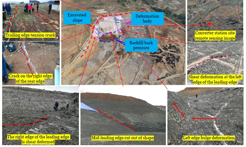
The slope of the Deposit slope in the proposed site area of the converter station of the Baihetan-Jiangsu UHV transmission project is generally in the SW-SE direction, the south side is higher, the top elevation is about 2490 m, the elevation range of the site area is 2448-2454 m, and the height difference is 36 m. The 10 m slope section is about 720 m, and the maximum height is about 36 m. It is located on the south side of the slope. The excavation slope rate is 1:3, except for the lowest part, which is 1:2. The overall slope of excavation is 16~20°, and the terrain is relatively slow. The original topography of the slope area is a gentle slope landform; the slope is about 8~10°, the local distribution of steep ridge, and the slope body vegetation is sparse, mainly cultivated land. On April 19, 2020, during the excavation of the slope in the excavation area on the west side of the proposed site area of the converter station, the slope showed obvious deformation. According to the field investigation, there are several transverse tension cracks at the back edge of the deformed slope, bulge and bulge deformation at the front slope foot, and shear cracks on both sides. After the deformation occurred, the back edge of the deformation was cut off immediately to reduce the load, and the cut soil was used to backfill the front slope foot of the deformation. After the treatment, the deformation rate of the deformation was significantly reduced. However, the deep displacement monitoring data showed that the deformation still existed in creep deformation, especially the possibility of overall instability after the excavation of the backfill soil at the slope foot (Fig. 1).
3. METHODOLOGY
3.1. Engineering Geological Conditions
3.1.1. Topography and Landform
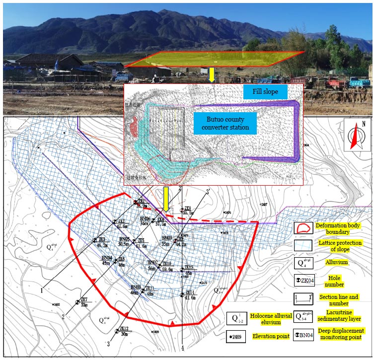
Butuo County is located in the central belt of Daliang Mountain, which belongs to the north extension of the Yunnan-Guizhou Plateau and is the original landform subregion of Liangshan Mountain in southwest Sichuan. In this area, the main landform types are Zhongshan and mountain plains; the general trend is low and steep in the southeast and high and slow in the northwest. The proposed site area is located on the southwestern edge of the Butuo Basin, which is the combination of the front of the fore-mountain diluvial fan and the accumulation terrace of the Butuo Basin. The terrain of the front of the diluvial fan in the southwest is relatively undulating, while the terrain in the middle and northeast is gentle and open. The overall terrain is inclined from southwest to northeast, with an elevation of about 2420~2490 m and a relative elevation difference of about 70 m (Fig. 2).
3.1.2. Formation Lithology
The field survey results show that the strata in the study area are mainly composed of Quaternary Holocene alluvium (Q4al+pl), Quaternary Upper Pleistocene to Holocene lacustrine sedimentary layer (Q3-4al+pl+l) and Quaternary Lower Pleistocene to Middle Pleistocene lacustrine sedimentary layer (Q1-2l). The deposit body slope is a complex deposit body landslide of “multi-genetic type soil” (Fig. 3).
Alluvial layer
 : mainly clay, yellow, brown yellow, plastic, wet to slightly wet, local pinch a small of pebbles, gravel, clay water content is rich, water loss is easy to dry crack, the layer is mainly distributed at the top of the slope, the thickness is generally 0.5~11.5 m.
Lacustrine sedimentary layer
 : mainly clay, brown, bluish-gray, and plastic, visible in the section of the sedimentary and structural bedding surface; the bedding surface is smooth, and the local gravel, gravel, sand, and peat soil layer, the layer is widely distributed in the slope deformation area, the thickness of 3.6~22.9 m.
Lacustrine sedimentary layer
 : mainly lacustrine sedimentary clay, partially mixed with silt, gravel, gravel and peat soil. The clay is brown, bluish-gray, grayish brown, hard plastic; the section can be seen as sedimentary and structural bedding surface; this layer of clay is easy to soften when exposed to water, and the strength decreases rapidly after exposure to the sun, the water loss is faster, and the rapid disintegration into fragmentation, this layer has not been exposed (Table 1).
| Soil Type | Natural Weight γ(kN/m3) |
Saturation Weight γsat(kN/m3) |
The Angle of Internal Friction φ(°) | Cohesive Force C(kPa) |
||
|---|---|---|---|---|---|---|
| Natural | Saturation | Natural | Saturation | |||
| Clay
|
17.0 | 17.5 | 12.8 | 11.7 | 23.2 | 20.0 |
| Clay
|
16.5 | 17.0 | 10.4 | 9.3 | 22.2 | 19.5 |
| Clay
-1 |
18.5 | 19.0 | 28.9 | 28 | 17.2 | 16.0 |
| Silt
-2 |
18.1 | 18.5 | 12.3 | 11.0 | 28.0 | 27.5 |
3.1.3. Hydrological Conditions
The surface water in the study area is mainly Temuri River and tributaries of Temuri River. Temuri River is located 250~300 m to the northwest of the proposed site, and the main channel is 10~15 m wide. The tributary of the Temuri River is located on the southwest side of the proposed site, with a width of 3~5 m and a depth of 1~3 m, and slopes on both sides. The type of groundwater is mainly pore water of loose Deposit slope, which is mainly replenished by atmospheric rainfall and surface gully water and is partially complementary with surface gully water. During the field investigation, the groundwater level was unstable and its dynamic change was great, and no stable groundwater level was found. According to the rainfall data of the Butuo County Meteorological Bureau, rainfall occurred on April 13, lasting about 7 h, and the rainfall reached 15.7 mm on that day.
4. ANALYSIS OF DEPOSIT SLOPE INSTABILITY MODE
4.1. Deposit slope deformation failure Characteristics
Field investigation, exploration and available data show that deformation cracks began to be found on April 19, 2020. The deformation signs are mainly manifested as a series of parallel transverse tension cracks developed on the back edge of the slope top, striking 125°. The width of the cracks is basically 1~3 cm, and the extension length is up to 30 m. There is no obvious fault on both sides of the cracks. Shear cracks are developed on both the left and right sides of the slope, of which the right-side cracks extend 175°, extend 22 m, open 5~10 cm, and are accompanied by obvious up-warping, and the height is about 15~20 cm. The extension direction of the left crack is about 265°, the extension length is about 30 m, the opening width is about 5~10 cm, and the up-warping height is about 10~20 cm. The bulge occurred at the foot of the side slope, with a direction of about 135°, an extension length of about 27 m, and a fracture bulge height of 20-25 cm (Fig. 4).
Based on the comprehensive judgment of topography, overburden boundary and slope deformation character istics, the rear edge of the slope deformation boundary is bounded by the most outer tension crack of the slope top, the front edge is bounded by the uplift and swelling of slope foot and shear deformation of slope excavation, and the shear crack developed on both sides of the boundary is bounded. The slope deformation gradually develops from the local deformation of the front edge to the whole deformation. As the uplift range of the front edge of the slope continues to increase, the deformation range also gradually expands from the front to the back and from the middle to the two sides. As a result, shear dislocation zones begin to appear on the boundary of both sides of the slope, and shear tension cracks occur on the flanks. Due to partial, incomplete excavation of the sloping front, the slope body produces uplift and bulge deformation at the bottom of the front of the first-grade slope release and thus forms a transverse bulge crack. The deformed body as a whole is an “arm-chair” shape; the overall deformation direction is 354°, the longitudinal length is about 180 m, the transverse width is about 260 m, the average thickness is about 15 m, the total square amount is about 70x104 m3, and it is a medium-sized soil slope.


4.2. Determination of Sliding Surface Range
It can be seen from the above analysis that continuous excavation causes deformation and instability of the slope. Due to complex engineering geological and hydrogeo logical conditions and superimposed human influence, it is difficult to judge the depth of the slip surface accurately. Therefore, 8 deep displacement monitoring points (BN01~BN08) were set up within the range of the deformable body, and the specific location was shown in Figs. (2 and 5) shows the change of displacement of each monitoring point at each moment. The monitoring data shows that the cumulative displacement of BN01~BN03 monitoring points located in the 1-1' profile within 8 days is -0.14 mm, 5.58 mm and 0.77 mm, respectively, and no obvious abrupt change is seen in the deep displacement curve. On the other hand, the deep displacement curves of BN04~BN06 monitoring points located on the 2-2' profile showed obvious abrupt changes, with the mutation depths at 21 m, 21.5 m and 12.5 m, respectively, and the cumulative displacement within 8 days was 7.74 mm, 11.88 mm and 7.47 mm, respectively.
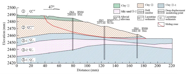
According to the drill hole, the slip zone is located at the junction of the plastic clay and the hard plastic clay, and the slip bed is mainly the hard plastic clay. The slip zone at the sloping front is slide-cut out from the inside of the hard plastic clay under the influence of stress, and the buried depth of the potential slip surface is about 12.5~21.5 m. The upper part of the slope deformation is shallow, and the middle and lower parts are deep. At the same time, the physical and mechanical parameters of slip-belt soil were obtained through laboratory tests, as shown in Table 2. The range and depth of the potential sliding surface of the deformable are determined by the deep displacement monitoring data and drilling data. The potential sliding surface of the deformable passes through the clay layer
and the clay layer
in the site, and the bottom is located at the interface of the clay layer
and the clay layer
-1. The overall length of the potential sliding surface is about 150 m, the maximum thickness is about 24 m, and the sliding surface is circular, wide, slow and long (Fig. 6).
| Sliding Zone Soil | Cohesive Force C(kPa) |
The Angle of Internal Friction φ (°) |
Weight γ (kN/m3) |
|---|---|---|---|
| Clay
|
17.2 | 9.0 | 17.0 |
4.3. Analysis of Deposit Slope Instability Mechanism
The instability mechanism of slope excavation of complex Deposit slope of “multi-genetic type soil” is very complicated. Engineering excavation changes the initial boundary condition of the slope, and once the equilibrium state is broken, irreversible deformation will occur. The excavated slope is affected by the construction disturbance, which leads to the destruction of the balance condition of the slope, and finally deformation and instability occur under the comprehensive action of many factors.
After the excavation of the Deposit slope, it mainly goes through the following stages:
(1) In the early stage of slope excavation, stress release and redistribution occur; the stress on the slope surface of the excavation section decreases, resulting in rebound deformation, while the stress increases within a certain depth range inside the slope. However, at this stage, the excavation depth is shallow, the stress reduction and increase are not large, and the slope body produces local spalling, but the overall deformation is not large (Fig. 7a, b).
(2) With the progress of excavation, shear stress concentrates locally at the foot of the slope and develops toward the middle and back of the slope, and tension cracks appear at the rear edge of the slope. The readjustment of stress in the slope makes it difficult for the slope to reach a new equilibrium state, and the slope surface collapses locally, and the free surface deforms significantly and develops toward the interior of the slope (Fig. 7c).
(3) Rainfall infiltration increases the moisture content of the soil mass of the Deposit slope. During the process of stress redistribution of the slope body after continued excavation, shear stress bands are generated at the front edge of the slope foot. Uplift occurs, which drives the soil movement at the back of the slope and further generates several groups of tension cracks at the back edge of the slope body (Fig. 7d).

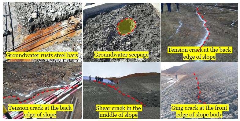

The soil layer at the site of the conversion station is mainly composed of plastic, hard plastic clay and silt, which has special engineering properties and poor water stability. It has high foundation bearing capacity and shear strength under natural conditions and is easy to slime and collapse when it meets water. It is easy to slip in slope geological conditions. According to local meteorological data, the site of the converter station was affected by continuous rainfall on April 13. On the one hand, the atmospheric precipitation produced strong erosion on the surface of the slope through surface runoff, reducing the strength of the upper loose soil; on the other hand, part of the surface water penetrated the loose surface of the slope, increasing the self-weight of the slope and increasing the sliding force. In the process of slope construction in the excavation area, a high and steep slope is formed, and the unloading speed is fast, but the progress of the lattice slope protection project does not fully keep up with the excavation rhythm.
The slope excavation changes the original slope shape and forms a free surface; the slope body produces stress redistribution, the slope foot stress concentration phenomenon, the sliding resistance force decreases, and the influence of rainfall reduces the strength of the Deposit slope soil, which directly leads to the deformation and failure of the slope. The deformation characteristics of the transformer show that the front edge of the slope is bulging and bulging, the rear edge is stretched and cracked, and there are shear dislocation zones on both sides of the boundary and shear tension cracks on the flanks. The deformation is caused by the sliding of the lower part and the loss of support of the upper soil. Therefore, the failure mode of the deformable body is traction creep slip-pull crack. Climate change will have a significant impact on rainfall intensity and frequency and then affect the structure, material composition, and structural characteristics of the accumulation body slope, which will have a crucial impact on the stability and reinforcement evaluation of the complex formation of the accumulation body slope.
5. PILE-TYPE REINFORCEMENT EFFECT ON DEPOSIT SLOPE
5.1. Reinforcement Scheme Design
According to the deformable characteristics of the Deposit slope of the converter station and the experience of similar landslide treatment projects, two types of anti-slide pile support schemes are designed: Scheme one is “embedded rectangular anti-slide pile in the middle of slope + rectangular double-row anti-slide pile at slope foot,” the section of the anti-slide pile in the middle of the slope is 2.0×2.5 m, the pile length is 22 m, and the section of the double-row anti-slide pile at slope foot is 2.0×2.5 m, the pile length is 35 m. The second scheme is “embedded circular anti-slide pile in the middle of slope + circular double-row anti-slide pile at slope foot.” the section diameter of the anti-slide pile in the middle of slope is 1.8 m, the pile length is 22 m, and the section diameter of double-row anti-slide pile at slope foot is 1.8 m, the pile length is 35 m.
5.2. Calculation Model and Boundary Conditions
In order to verify the effectiveness of the reinforcement treatment scheme, the deformation of the slope before and after reinforcement is numerically calculated. A numerical calculation model (Fig. 8) was established using a typical profile, which was divided into 8251 units and 8456 nodes, as shown in Fig. (6). One-dimensional pile element is used for anti-slide pile, linear elastic model is used for pile and soil hardening model is used for rock and soil mass. A linear elastic model was used for the two types of anti-slide piles. The elastic modulus of rectangular anti-slide piles was E=34 GPa, and Poisson's ratio μ=0.23. Elastic modulus E=30 GPa, Poisson's ratio μ=0.20. The bottom of the model is a fixed boundary, the top is a free boundary, and the other faces limit the normal displacement.
6. RESULTS AND DISCUSSION
6.1. Analysis of Reinforcement Simulation Calculation Results
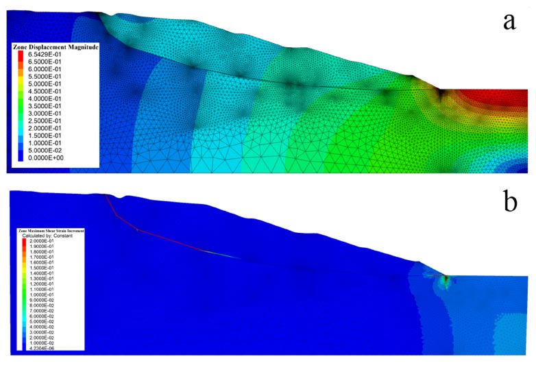
Fig. (9) shows the displacement and maximum shear strain of the Deposit slope after excavation. It can be seen that the slope deformation before reinforcement is mainly concentrated at the foot of the slope. The maximum displacement is below the primary horse track, reaching 55.4 cm, and the displacement at the back edge of the slope is about 15 cm, which is larger than the displacement at the front edge of the slope revealed by field investigation and deep displacement monitoring results. The results of small trailing edge displacement are basically consistent. The maximum shear strain in the reinforced front slope is concentrated in the existing slip zone; the maximum shear strain is at the back edge, the foot of the slope, and the middle of the slope is slightly smaller. The deformation of the slope mainly shows that the deformation of the front edge of the slope body drives the rear soil down, which is a typical sliding mode of “traction creep slide-tension crack.”
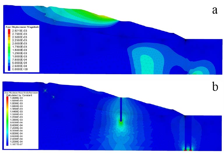
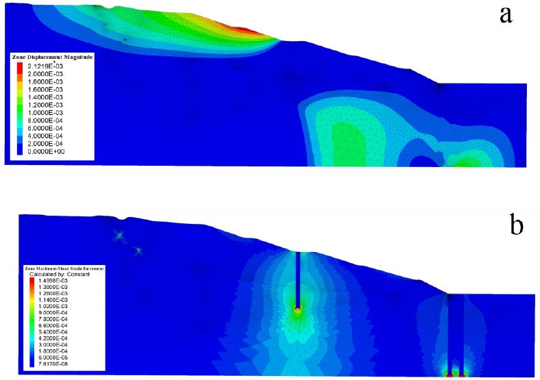
Figs. (10 and 11) are the displacement cloud maps of deformities under the two reinforcement methods, respectively. It can be seen that after the treatment of the two reinforcement schemes, the natural sliding deformation occurs in the middle of the slope, and the maximum deformation is located on the rear slope surface of the anti-slide pile. Under the two treatment schemes, there is no obvious displacement of the deformed slope foot, and the deformed body remains basically stable. After reinforcement, the maximum shear strain of the deformed form is located in the soil around the anti-slide pile and concentrated at the pile bottom, among which the shear strain around the anti-slide pile in the middle of the slope is larger. The maximum shear strain under reinforcement plan 1 and 2 is 1.99 and 1.49, respectively. After the anti-slide pile reinforcement, there is no obvious shear strain increment zone inside the slope, the displacement and shear strain of the soil in the slip zone are obviously reduced, and the anti-slide pile has no obvious displacement.
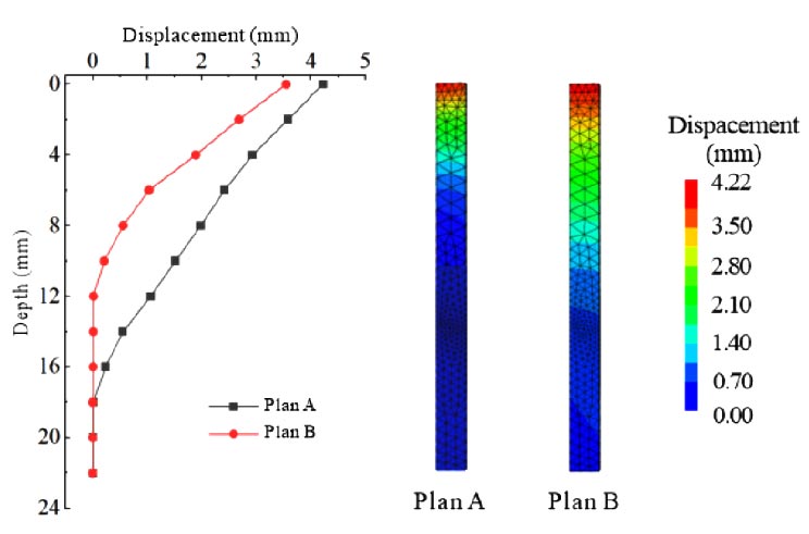
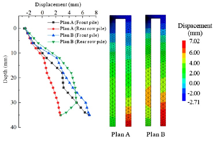
The displacement cloud map and displacement curve of the supporting structure under the two schemes are shown in Figs. (12 and 13). After the anti-slide pile reinforcement, the displacement of the Deposit slope is mainly concentrated in the middle and rear of the slope body. Then, the anti-slide pile in the middle of the slope body is squeezed to produce displacement. According to the deformation cloud map, it can be found that the deformation of the middle anti-slide pile is mainly at the top, and the pile bottom has no obvious displacement under the two schemes. The double-row pile at the foot of the slope has a large deformation at the bottom of the pile, and the top of the double-row pile moves in the reverse direction under the action of torque, and the displacement of the double-row pile in front of the pile is significantly larger than that of the rear pile. Although the anti-slide piles under the two schemes do not penetrate the underlying bedrock, they both play a good role in embedding and effectively limit soil displacement. Compared with the two reinforcement schemes, the displacement of rectangular anti-slide piles is lower than that of circular piles, and the effect of preventing the upper soil from sliding is better.
6.2. Analysis of Slope Stability Calculation Results
At the same time, the strength reduction method is used to calculate the stability coefficient of the deformable slope before and after reinforcement. Since the moisture content of the soil in the site is close to saturation, the parameters under saturation state are used as the calculation parameters of the general working conditions, and the two working conditions of general and earthquake are mainly considered for calculation. The slope of this project is a permanent slope with a safety grade of one. The exploration area belongs to the seismic VIII zone, and the seismic acceleration is 0.273 g (Table 3).
| Calculation Condition | Loading Combination | Reinforcement Scheme | Safety Factors (Ks) |
Stability Safety Factors (Fs) |
|---|---|---|---|---|
| Natural condition | Be-self weight | Schemes one | 1.35 | 1.43 |
| Schemes two | 1.35 | 1.38 | ||
| Earthquake condition | Be-self weight+Earthquake | Schemes one | 1.15 | 1.19 |
| Schemes two | 1.15 | 1.13 |
The stability calculation results show that the stability coefficient Fs of the deformable body is 1.43 under natural conditions and 1.19 under earthquake conditions after treatment under reinforcement scheme 1. The stability coefficient Fs of the deformable body is 1.38 under natural conditions and 1.13 under earthquake conditions after the treatment of reinforcement scheme 2. The stability coefficient of the two treatment schemes can meet the design requirements, which indicates that the engineering treatment scheme for landslides is reasonable and effective.
However, according to the investment budget, the total investment of the treatment engineering cost of a rectangular anti-slide pile is more economical than that of a circular pile, and the economic benefit of a circular pile is better than that of a rectangular pile. From the initial construction cost, long-term maintenance, and potential failure cost, it is advisable to use round pile support to strengthen some deformed external slopes. At the same time, to the potential ecological environmental impact in the construction and operation process, protection strategies should be adopted, and green restoration operations should be carried out in time after slope support treatment.
| Parameters /Soil Type |
Reduction Factor | Reduction of Internal Friction Angle (°) | Reduction Cohesive Force (kPa) | Parameters /Soil Type |
Reduction Factor | Reduction of Internal Friction Angle (°) | Reduction Cohesive Force (kPa) |
|---|---|---|---|---|---|---|---|
| Clay
|
0.50 | 4.78 | 2.61 | Clay
-1 |
0.50 | 9.17 | 5.27 |
| 0.75 | 7.16 | 3.91 | 0.75 | 13.76 | 7.90 | ||
| 1.00 | 9.55 | 5.21 | 1.00 | 18.34 | 10.53 | ||
| 1.25 | 11.94 | 6.51 | 1.25 | 22.93 | 13.16 | ||
| Clay
|
0.50 | 6.09 | 3.91 | Silt
-2 |
0.50 | 3.06 | 1.05 |
| 0.75 | 9.13 | 5.87 | 0.75 | 4.59 | 1.58 | ||
| 1.00 | 12.17 | 7.82 | 1.00 | 6.12 | 2.10 | ||
| 1.25 | 15.21 | 9.78 | 1.25 | 7.65 | 2.63 |
7. PILE PARAMETERS REINFORCEMENT EFFECT ON DEPOSIT SLOPE
In order to further clarify the influence of parameters of rectangular double-row anti-slide piles on the reinforcement effect of Deposit slope, this section still uses the strength reduction method in numerical simulation to conduct an in-depth study on the evaluation of the influence of different row spacing, pile section size, pile length and pile spacing on the reinforcement effect of anti-slide piles. The parameters of the slope soil mass reduction model are shown in Table 4.
7.1. Double-row Anti-slide Pile Row Spacing
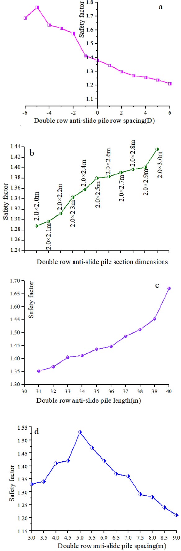
In this section, the double-row anti-slide pile row spacing is set as 1 times pile diameter, 2 times pile diameter, 3 times pile diameter, 4 times pile diameter, 5 times pile diameter, and 6 times pile diameter, respectively, to analyze the reinforcement effect on the Deposit slope. The left side of the base pile row spacing is negative, and the right-side is positive. After modeling and calculation, the curve of the safety factor of pile slope with pile row distance is shown in Fig.(14a). When the second row of anti-slide piles is arranged at -5 times the pile diameter, the reinforcement effect is the best, and the safety factor is 1.765.
7.2. Double-row Anti-slide Pile Diameter
The pile diameter is optimized on the basis of the row spacing of anti-slide piles determined above, that is, -5 times the pile diameter. The pile section sizes used in this excerpt are 2.0x2.5 m, with each grade increasing or decreasing by 0.1 m. After modeling calculation, the variation curve of the safety factor of the pile slope with the size of the pile section is shown in Fig. (14b). As can be seen from the figure, the safety factor of the deposit body slope increases gradually with the increase of pile section size within a certain range. When the pile section size is 2.0×3.0 m, the safety factor is 1.436. The use of this scheme to strengthen the deposit body slope can keep the slope in a stable state.
7.3. Double-row Anti-slide Pile Length
Based on the selection of a pile section size of 2.0×3.0 m, as mentioned above, the pile length is optimized to reduce the length of the pile. The analyzed pile lengths are 31~40 m, respectively, and each grade is reduced by 1.0 m. After modeling calculation, the variation curve of the safety factor of the Deposit slope with pile length is shown in Fig. (14c). When the pile length is 31 m, the safety factor of the slope is 1.352, and the slope is in a stable state.
7.4. Distance between Double Rows of Anti-slide Piles
Based on the pile parameters mentioned above, the pile row spacing is -5 times the pile diameter, the pile section size is 2.0×3.0 m, and the pile length is 31 m. Here, the pile spacing of double-row anti-slide piles is set at 3~9 m, and the pile spacing is increased or decreased by 6 m and 0.5 m for each grade. After modeling calculation, the curve of the d deposit slope safety factor with pile spacing is shown in Fig. (14d). The safety factor is 1.41 when the pile length is reduced to 4.0 m or when the pile spacing is increased by at least 7.0 m; the requirements are also met.
8. SEISMIC STRENGTHENING MECHANISM OF DOUBLE-ROW ANTI-SLIDE PILE REINFORCEMENT DEPOSIT SLOPE UNDER EXTREME CONDITIONS
8.1. Calculation Scheme
In order to clarify the anti-seismic strengthening mechanism of double-row piles on the complex Deposit slope of the converter station under extreme conditions, a dynamic calculation of the Deposit slope was carried out (Chen 2014; He 2012; Yan 2010; Xiao 2007). The parameters of the model rock mass are shown in Table 5. The elastoplastic model is selected for the constitutive model, and the anti-slide pile length is 35 m. In FLAC3D, the straight-line segment between the two structural nodes is represented as the element component of the pile, and the pile can be formed by combining multiple structural elements. The structural parameters of the anti-slide pile are shown in Table 6.
8.2. Seismic condition design
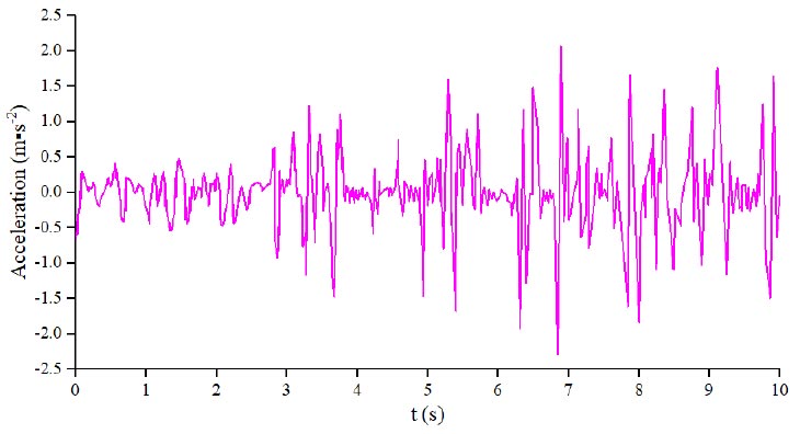
The key to the study of seismic strengthening mechanisms under extreme working conditions lies in the selection of seismic waves. Here, the acceleration time history curve of 10s before the Wenchuan earthquake wave is selected (Fig. 15), the Deposit slope model is dynamically loaded, the boundary condition of the model is set as free field, the damping ratio is set as critical damping ratio D=0.05, and the local damping αL =0.1571.
8.3. Dynamic Response of Deposit Slope
Comparison of horizontal displacement of Deposit slope under earthquake conditions: the maximum horizontal displacement before support is about 98.71 cm and decreases to 12.17 cm after support. Comparison of plastic zone location of deposit body slope: the plastic zone area of slope surface and front edge of slope body decreases obviously after support, and the local plastic zone of deposit body slope disappears after support. Comparison of the maximum principal stress of the Deposit slope: the maximum principal stress before the support is mainly concentrated in the inner slope, and the principal stress on the slope after the support is significantly reduced. In general, the deformation of the pile slope is reduced, the stability is improved, and the seismic resistance of the slope is improved after the anti-slide pile support. At the same time, due to the influence of seismic effect, the slope top of the Deposit slope is easy to form, and the amplification effect of site peak acceleration (PGA) leads to the stress concentration at the slope top of the Deposit slope, which is easier to deform. According to the monitoring of the PGA amplification coefficient at the monitoring point of the Deposit slope, the PGA amplification coefficient decreases gradually with the increase of slope. After the support, the overall PGA amplification factor of the side slope of the Deposit slope is improved, indicating that the anti-slide pile can effectively reduce the acceleration of the nearby rock and soil body and improve the seismic performance of the Deposit slope (Fig. 16a).
Further, this section analyzes the internal force of double-row anti-slide piles, taking the shear force before seismic load as the starting point and only considering the dynamic effect. The change law of shear force at the monitoring point of anti-slide piles is shown in Fig. (16b). As can be seen from the figure, the shear force changed from negative to positive after the input of local seismic wave 1.0s and rapidly increased to 681.83 kN. During the period of earthquake action from 1~4 s, the shear force gradually changes from positive to negative. It fluctuates, which is caused by the offset of the inverse seismic wave acceleration. After 4 s, the shear force gradually increased until the end of the earthquake, and the maximum shear force reached about 1031.93 kN. According to the analysis of the shear data, we can also know that the seismic action can not only cause positive and negative fluctuations of the shear force of the anti-slide pile but also make the shear force reach the maximum positive value.
| Parameters/ Soil Type |
Bulk Modulus (GPa) | Shear Modulus (GPa) | Cohesive Force (kPa) | The Angle of Internal Friction φ (°) | Tensile Strength (kPa) | Density (g▪cm-3) |
|---|---|---|---|---|---|---|
| Clay
|
0.113 | 0.096 | 5.21 | 9.55 | 1.38 | 1.693 |
| Clay
|
0.354 | 0.173 | 7.82 | 12.17 | 1.74 | 1.709 |
| Clay
-1 |
0.444 | 0.251 | 10.53 | 18.34 | 2.23 | 1.825 |
| Silt
-2 |
0.057 | 0.032 | 2.10 | 6.12 | 0.00 | 1.802 |
| Density (g▪cm-3) |
Elastic Modulus (GPa) | Poisson's Ratio | Cross-sectional Area (m2) | Y-axis Moment of Inertia (m4) | Polar Moment of Inertia (m4) | ||
|---|---|---|---|---|---|---|---|
| 2.68 | 34 | 0.23 | 5 | 1.28 | 2.57 | ||
| Tangential coupled spring stiffness (GPa ▪m-1) |
Tangentially coupled spring cohesion (GPa ▪m-2) |
Normal coupling spring stiffness (GPa ▪m-1) |
The cohesiveness of normal coupled spring (GPa ▪m-2) |
||||
| 12000 | 12 | 12 | 12000 | ||||
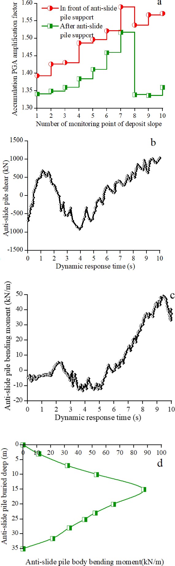
Here, we also monitored the bending moment of the double-row anti-slide pile, and the dynamic change of the bending moment at the monitoring point is shown in Fig. (16c). When the seismic wave acts for 0~1 s, the bending moment of the monitoring point fluctuates around 0 kN/m and has a tendency to increase slightly to positive. The positive value of the bending moment gradually increases and then decreases to a negative value when the seismic wave acts from 1~4 s. After the local seismic wave action for 4 s, the bending moment gradually increases from negative to positive, and the maximum value reaches 40.21 kN/m. In this section, the variation of pile bending moment with a buried depth of double-row anti-slide pile after the earthquake is investigated. Fig. (16d) shows that with the increase of pile buried depth, the bending moment presents a “right convex” curve shape; from the top to the bottom of the pile, the bending moment gradually increases along the pile body and then gradually decreases. The maximum bending moment appears at the buried depth of about 15 m, which is 87.21 kN/m, which should be the most dangerous section of an anti-slide pile. It will help to prevent the bending damage of the anti-slide pile.
8.4. Discussion on Seismic Strengthening Mechanism
Seismic waves propagate in the slope of complex Deposit slope of “multi-genetic type soil,” which is easy to produce reflection and refraction phenomenon. At the same time, due to the different responses of different strata to seismic waves, the slope will appear to be stretching, deformation and even instability. At the same time, the seismic wave will also produce reflection and refraction when passing through the interface of different soil layers in the Deposit slope, which further aggravates the instability of the slope. According to the numerical simulation results of the seismic response of the slope under extreme conditions, the horizontal displacement and principal stress of the slope top are large, the plastic deformation area is also large, and the PGA amplification factor is greater than 1.25. After the double-row anti-slide pile support, the indexes of each measuring point are significantly reduced, and the overall stability of the Deposit slope is obviously improved. This is because the anti-slide pile has the function of compaction and stiffness support, which can obviously improve the mechanical properties of the surrounding Deposit slope. When the seismic wave propagates in the form of a surface wave, part of the seismic wave will directly reach the anti-slide pile body. The other part will first reach the soil between the anti-slide pile and then spread to the pile body and finally dissipate the seismic wave into the rock and soil body of the anchorage section through the anti-slide pile body.
Based on the analysis results of the above section, it can be seen that the shear force and bending moment of the anti-slide pile increase gradually and then decrease slowly with the seismic wave, and finally reach the maximum value. Therefore, it is necessary to strengthen the stirrup arrangement of the pile body, pile top and other positions and add bending reinforcement at the maximum bending moment so that the anti-slide pile does not easy to fail. In particular, it should be noted that under the action of the earthquake, it is more necessary to adopt a conservative design of an anti-slide pile; it is recommended to take 1.2~1.3 times the maximum bending moment to calculate; at the same time, it should also be combined with the distribution of internal forces of the pile and the addition of stirrups in the part of large shear force, enhance the shear performance and improve the seismic effect, and reasonably increase the safety factor.
9. FOLLOW-UP RESEARCH PLAN
We will supplement the genetic study of sedimentary slopes under different soil compositions or environmental conditions in the follow-up study. In the future, we will monitor the long-term deformation law of the slope of the accumulation body and conduct an in-depth evaluation of the durability and long-term effectiveness of the anti-slide pile combined with seasonal changes and extreme weather events. In the future, we will also carry out in-depth research on slope stability under the condition of increasing rainfall intensity and frequency. We will supplement the influence of soil mechanical property changes on slope stability in subsequent studies and carry out a sensitivity analysis to provide a more powerful understanding of slope system behavior under different conditions. The evaluation of the stability of the accumulation slope under the influence of different seismic magnitudes, durations, and seismic wave directions will be carried out in the follow-up study. Advanced technical tools, such as machine learning and other cutting-edge technologies, may indeed improve the accuracy of slope failure prediction and optimize reinforcement design. We will carry out relevant research work in the subsequent research. We will strengthen our engagement with stakeholders in the areas where deposit slopes are located and enlist the help of communities to promote understanding and cooperation in geo-disaster-prone areas better.
Subsequently, we will complete the above part of the study to re-evaluate the reinforcement slope and timely adjust the reinforcement strategy based on the latest findings and development validation in the field of slope reinforcement.
CONCLUSION
Through the field investigation, field monitoring, and numerical simulation analysis of the “multi-genetic type soil” complex deposit slope in the converter station, the excavation instability mode and reinforcement effect are deeply explored. The conclusions are as follows:
(a). slope soil of complex accumulation body composed of “multi-genetic soil type” has high water sensitivity, and the soil deformation is intensified after a short period of heavy rainfall. Rainfall further weakened the shear strength of the site's highly water-sensitive clay layer, causing the soil to swell and bulge at the foot of the slope. The formation of tension cracks accompanies the creep deformation of the slope, and finally, the instability mode called “traction creep-tension cracks” is formed.
(b). Both circular and rectangular anti-slide piles significantly reduce the amount of slope body deformation; employing circular anti-slide piles for addressing this type of deposit slope provides enhanced anti-slide retention and economic benefits.
(c). Under the action of an earthquake, the top deformation of the anti-slide pile is the largest, the shear force and bending moment increase first and then decrease with the increase of seismic wave, and the maximum bending moment value is about 1/2 of the anti-slide pile body.

