All published articles of this journal are available on ScienceDirect.

Shear Performance and Sustainability Assessment of Reinforced Concrete Beams with Longitudinal Hollow Cores

Abstract
Objective
This study investigates the shear performance of reinforced concrete beams containing longitudinal hollow cores, focusing on hollow-core diameter, shear span-to-effective depth ratio (a/d), and environmental benefits from reduced concrete consumption.
Methodology
An experimental program was conducted on six reinforced concrete beam specimens subjected to four-point bending with two symmetrically applied concentrated loads until failure. Hollow-core diameter and a/d were varied. Measured shear capacities were compared with ACI 318 predictions. Material Production Energy (MPE) and CO2 emissions were evaluated from the material quantities used in each specimen.
Results
Increasing hollow-core diameter reduced beam stiffness and ultimate shear capacity, with reductions of up to 19.4% relative to the solid beam. Increasing a/d from 2.5 to 3.0 reduced ultimate shear capacity by approximately 10%. All specimens failed in a brittle diagonal shear mode. ACI 318 consistently underestimated measured shear capacities, providing conservative predictions. Reduced concrete quantities also decreased MPE and CO2 emissions.
Discussion
The results show that hollow-core diameter and a/d affect shear strength, cracking behavior, and stiffness. Longitudinal hollow cores can reduce material production impacts while maintaining acceptable shear performance within the investigated range.
Conclusion
Longitudinal hollow cores provide a viable approach for reducing concrete consumption and environmental impacts without disproportionate loss of shear capacity within the investigated geometric limits. Further studies with larger specimen sizes and repeated specimens are required to verify these findings.
1. INTRODUCTION
Previous studies have extensively investigated the use of voids and hollow cores in reinforced concrete members as a means of reducing concrete consumption while maintaining adequate structural performance. Ibrahim et al. [1] investigated the effect of ball shape and spacing on the structural behavior of reinforced concrete bubbled slabs, demonstrating the potential of internal voids to reduce material consumption while maintaining structural efficiency. Similarly, studies on hollow-core slabs have shown that the presence and geometry of internal voids can significantly influence cracking, stiffness, and shear resistance [2-7].
For reinforced concrete beams, Al-Nuaimi et al. [8] experimentally compared seven hollow and seven solid beams subjected to combined bending, shear, and torsion. Their results showed that the hollow beams generally exhibited lower cracking and failure loads and greater deformation than their solid counterparts. Alshimmeri and Al-Maliki [9] further investigated hollow reinforced concrete beams under partial uniformly distributed loading, highlighting the influence of the hollow configuration on structural efficiency. More recently, Al-Maliki et al. [10] examined hollow reinforced concrete beams under partial uniformly distributed loading, confirming the potential of longitudinal voids to reduce material consumption while maintaining satisfactory structural performance. Alharishawi et al. [11] also investigated the shear stresses of hollow lightweight concrete beams and demonstrated the influence of hollow sections on their shear response.
Recent research has increasingly focused on the geometry and size of longitudinal openings. Kumbasaroglu and Korkmaz [12] examined the effect of longitudinal circular hollows on the flexural strength of reinforced concrete beams, while Abd [13] numerically investigated beams containing single and multiple longitudinal hollow openings. Ahmed et al. [14] explored voided reinforced concrete beams using topology optimization, whereas Hekal et al. [15] investigated the flexural strength of multi-hollow-core reinforced concrete beams reinforced with advanced materials. These studies indicate that the location, size, number, and configuration of longitudinal voids are important parameters governing the structural response of hollow beams. The influence of longitudinal hole shape and size has also been examined in recent numerical and experimental investigations of RC beams, reinforcing the importance of optimizing void geometry rather than considering material reduction alone.
Other investigations have specifically addressed the shear behavior of hollow reinforced concrete members. Aziz [16] investigated the shear strength of hollow RC beams with transverse internal ribs, demonstrating the importance of the internal configuration in resisting shear. Saeed and Abubaker [17] examined the shear strength and behavior of high-strength reinforced concrete beams without stirrups, providing additional insight into the parameters governing shear resistance. He et al. [18] investigated the shear behavior of concrete beams reinforced with GFRP-steel hybrid stirrups, although their study focused on reinforcement rather than longitudinal voids.
Numerical approaches have also been employed to complement experimental investigations. Yuan et al. [19] studied hollow concrete-filled rectangular GFRP tube beams under bending, while, of particular relevance, Ismael and Hameed [20] experimentally investigated hollow-core reinforced self-compacting concrete beams with different longitudinal hollow-core diameters. Their results demonstrated that increasing the hollow-core size could reduce concrete consumption while also affecting cracking and ultimate strength. The study also included an optimization and sustainability assessment, establishing a direct relationship between hollow-core geometry, structural performance, and material savings. In addition, Nguyen et al. [21] experimentally investigated the torsional behavior of reinforced concrete beams strengthened with hybrid carbon and basalt FRP sheets, while Said et al. [22] examined the torsional response of hybrid fiber-reinforced concrete beams. Although these studies primarily focused on shear or torsional resistance rather than longitudinal hollow cores, they emphasize the significant influence of reinforcement, material properties, and structural configuration on the overall behavior of reinforced concrete beams.
Despite these contributions, limited experimental research has simultaneously examined the effects of longitudinal hollow-core diameter and shear span-to-effective depth ratio (a/d) on the shear performance of conventional reinforced concrete beams, while also quantifying the associated reductions in embodied energy and CO2 emissions. Therefore, the present study investigates these parameters experimentally and evaluates the measured shear capacities against ACI 318 predictions, while simultaneously assessing the environmental benefits resulting from concrete-volume reduction.
2. MATERIALS AND METHODS
2.1. Experimental Program
The experimental program involved testing six rectangular reinforced concrete beams, each with identical overall dimensions of 125 mm × 150 mm × 1000 mm. To achieve concrete removal ratios of 2.1%, 3.3%, and 4.7% of the total beam volume, the specimens were divided into two groups. In the first group, the primary variable was the diameter of the embedded longitudinal pipe, with diameters of 20 mm (SB2), 25 mm (SB3), and 30 mm (SB4). These diameters were chosen to represent practical ranges of internal voids typically used in lightweight or service-integrated concrete members, while ensuring that the beams’ overall structural performance remained adequate. A summary of the experimental program, including specimen specifics, is demonstrated in Table 1.
| Group No. | Details of Group | Beam Code | Beam Type | Hollow-core Diameter (mm) | a/d | a mm |
b mm |
Concrete Elimination in Volume % |
|---|---|---|---|---|---|---|---|---|
| 1 | Changing the diameter of hollow-core | SB1 | Solid | - | 2.5 | 300 | 300 | - |
| SB2 | Hollow-core beam | 20 | 2.5 | 300 | 300 | 2.1 | ||
| SB3 | Hollow-core beam | 25 | 2.5 | 300 | 300 | 3.3 | ||
| SB4 | Hollow-core beam | 30 | 2.5 | 300 | 300 | 4.7 | ||
| 2 | Changing the a/d | SB4 | Hollow-core beam | 30 | 2.5 | 300 | 300 | 4.7 |
| SB5 | Hollow-core beam | 30 | 2.75 | 330 | 240 | 4.7 | ||
| SB6 | Hollow-core beam | 30 | 3 | 360 | 180 | 4.7 |
The gradual increase in pipe diameter allowed for a systematic assessment of the impact of concrete removal ratio on the shear performance of the specimens. In the second group, the variable parameter was the (a/d), which was adjusted to 2.5 for SB4, 2.75 for SB5, and 3.0 for SB6. These values were chosen to cover a transition range between shear-dominated and flexure-dominated performance, thereby enabling evaluation of the interaction between internal hollow sections and shear span on the load-carrying capacity and failure mechanisms of the beams. All specimens were demolded after 24 hours and cured under identical conditions using water curing for 28 days at room temperature. Maintaining consistent curing conditions was essential to minimize variability in concrete strength and stiffness, ensuring that the observed changes in structural behavior are primarily controlled by the investigated variables rather than variations in material properties. The adopted curing regime is expected to have a direct impact on crack development, bond characteristics, and overall load–deflection response of the beam specimens. The details of the experimental program and the overall beam configuration are illustrated in Fig. (1).
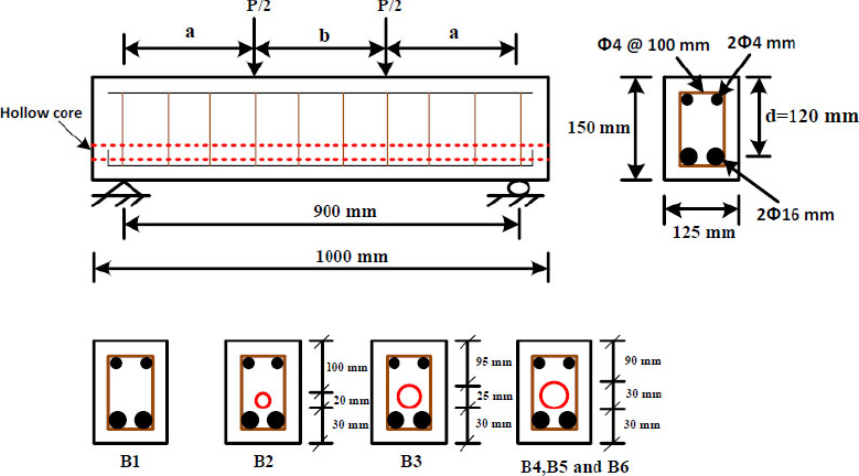
Specifications of the specimens.
2.2. Concrete Components
Normal concrete (NC) was utilized to fabricate all beam specimens of this study. This section provides an overview of the properties of the constituent materials, including cement, fine and coarse aggregates, steel reinforcement, and the plastic pipes installed longitudinally within the beams. Cement (Type I), commercially available, was utilized in all concrete mixtures. Natural sand sourced was utilized as fine aggregate, while crushed coarse aggregate with 10mm obtained from the same region was employed in this study. Fine and coarse aggregates satisfied the grading and quality requirements specified in [23]. The compressive strength of concrete was determined using three 150 mm cube specimens tested at 28 days in accordance with relevant standards. The average strength (f'c) was determined to be 30 MPa, with a coefficient of variation of 1%, indicating consistent material quality.
2.3. Steel Reinforcement
The longitudinal reinforcement in all specimens consisted of 2ϕ16 mm with 525 MPa yield strength. Shear reinforcement was provided by ϕ4 mm deformed stirrups, having a yield strength of 345 MPa, which were secured in place using ϕ4 mm smooth steel tying wires. As shown in Fig. (2). The effective depth (d) of the beams, which refers to the vertical distance from the top compression fiber to the centerline of the tensile reinforcement, was determined to be 120 mm.
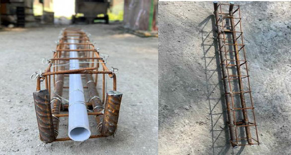
Reinforced cage of beam specimens.
The ratio (ρ) was calculated as:
and was equal to 2.6808% for all specimens
2.4. The Recycled Plastic Pipes
Recycled plastic pipes with a wall thickness of 1.5 mm were used to form the longitudinal hollows within the beam specimens. Each pipe was placed along the beam’s longitudinal axis to create a continuous void. Being chemically inert, the recycled plastic does not undergo any chemical reaction with any constituents of the concrete mixture. The placement and configuration of the pipes are illustrated in Fig. (3).
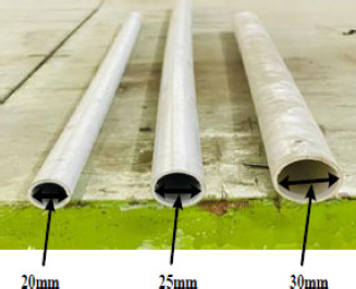
The recycled plastic pipes in this study create longitudinal hollows.
The pipe was positioned longitudinally parallel to the tensile reinforcement with a constant vertical distance from the bottom reinforcement in all specimens. The location was kept identical for all hollow-core beams to isolate the effect of hollow diameter.
2.5. Testing Procedure
After cleaning and painting a thin white layer on all beam specimens to improve the visibility of crack formation, A 600 kN universal hydraulic testing machine was employed to test the beams. in the Civil Engineering Laboratory at Diyala University. As shown in Fig. (4), a four-point bending setup with two symmetrically applied concentrated loads, rather than a "two-point bending" setup, was applied to each beam. A linear variable displacement transducer (LVDT) was positioned at midspan to continuously record vertical deflections throughout the loading process. Since the main target of the study was to assess the global shear performance and overall load–deflection response of the beams under symmetric loading, the midspan deflection was considered sufficient and representative for comparative assessment among the tested specimens.
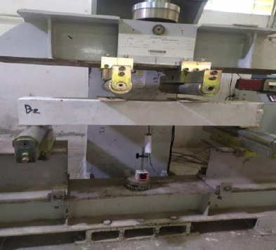
The beams are set up for testing.
3. RESULTS
3.1. Failure of Specimens and Crack Development
The crack patterns observed at failure are illustrated in Fig. (5).
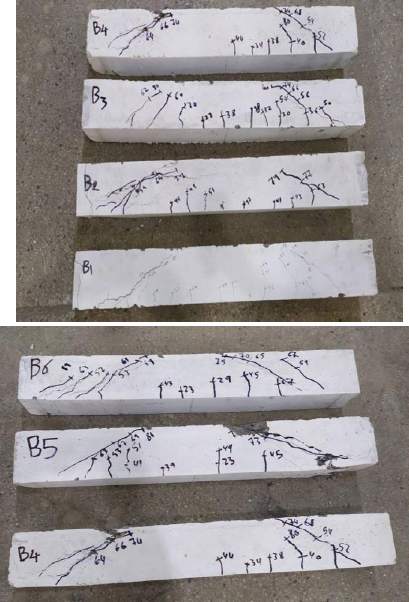
Pattern of failure cracks of the beam specimens.
3.2. Crack and Ultimate Shear Loads
3.2.1. Load–deflection Response and Ultimate Deflection
Figures 6 and 7 illustrate the impacts of hollow core diameter and (a/d) on the midspan load–deflection performance of the beam specimens, while Table 3 summarizes the corresponding ultimate deflections.
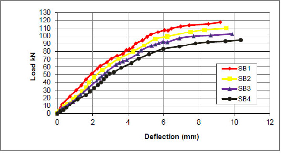
Impact of the diameter of the hollow beam on load – deflection.
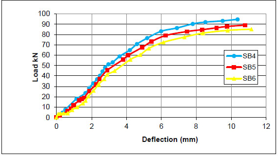
Impact of (a/d) on load–deflection.
| Group No. | Details of Group | Beam No. | Compressive Strength (MPa) |
Crack Load Pcr (kN) |
Diminution in Pcr % | Ultimate Load Pu (kN) |
Diminution in Pu % | Failure Mode |
|---|---|---|---|---|---|---|---|---|
| 1 | Changing the diameter of hollow-core | SB1 | 30 | 26 | - | 117.5 | - | shear |
| SB2 | 30 | 22 | 15.4 | 109.8 | 6.6 | shear | ||
| SB3 | 30 | 20 | 23.1 | 102.3 | 12.94 | shear | ||
| SB4 | 30 | 19 | 26.9 | 94.7 | 19.4 | shear | ||
| 2 | Changing the a/d | SB4 | 30 | 19 | - | 94.7 | - | shear |
| SB5 | 30 | 18 | 5.3 | 89.1 | 5.9 | shear | ||
| SB6 | 30 | 16 | 15.8 | 85.2 | 10 | shear |
| Group No. | Details of Group | Beam |
Ultimate Deflection ∆u (mm) |
Increase in ∆u % |
|---|---|---|---|---|
| 1 | Changing the diameter of the hollow core | SB1 | 9.212 | - |
| SB2 | 9.54 | 3.6 | ||
| SB3 | 9.88 | 7.3 | ||
| SB4 | 10.36 | 12.5 | ||
| 2 | Changing a/d |
SB4 | 10.36 | - |
| SB5 | 10.79 | 4.2 | ||
| SB6 | 11.16 | 7.7 |
4. DISCUSSION
4.1. Failure of Specimens and Crack Development
Figure 5 illustrates that all six beam specimens experienced shear failure during testing, and their overall crack performance followed a similar pattern. At the initial stages of loading, short flexural cracks appeared within the pure bending-dominated region in the zone between the load application points. These cracks grew in the vertical direction, while new flexural cracks appeared in the same zone. Simultaneously, new cracks began to develop within the shear spans between the loading points and the beam supports. With additional loading, diagonal shear cracks abruptly appeared in the shear spans on one or both sides of the beam, either simultaneously or sequentially. Progressive widening and deepening of the main diagonal crack near the loading point ultimately led to shear failure. All beams failed abruptly with an audible sound, characteristic of brittle shear performance.
4.2. Crack and Ultimate Shear Loads
The diagonal crack load is defined as the load at which an inclined crack first develops within the shear span, extending from the support toward the loading point. The ultimate shear load is defined as the load corresponding to the onset of shear failure. As shown in Table 2, the observed failure patterns indicate that the diagonal crack either developed directly within the shear span and propagated toward the loading point or originated from an inclined flexural crack that subsequently extended toward the point of loading.
4.2.1. Effect of Longitudinal Hollows
Table 2 presents the ultimate shear capacity and the initial crack load for the six beam specimens. The data reveal that the presence of longitudinal voids has a more pronounced impact on the initiation of cracks than on the ultimate shear strength. As the volume of removed concrete increases, the load required to produce the first visible crack decreases noticeably, whereas the reduction in ultimate shear capacity is comparatively modest. For instance, beams SB2, SB3, and SB4, which contain longitudinal voids with diameters of 20 mm, 25 mm, and 30 mm respectively, experience concrete volume reductions of 2.1%, 3.3%, and 4.7%. These reductions correspond to decreases in the initial crack load of 15.4%, 23.1%, and 26.9%, respectively. In comparison, the ultimate shear strengths are reduced by only 6.6%, 12.9%, and 19.4%.
This performance indicates that the onset of cracking is more sensitive to changes in sectional stiffness than the ultimate shear resistance. The relatively limited reduction in ultimate shear strength may be attributed to the combined contribution of the conventional shear-resisting mechanisms, including aggregate interlock, dowel action of longitudinal reinforcement, stirrup contribution, and the concrete compression zone. However, the individual contribution of each mechanism was not experimentally quantified in this study. Therefore, while longitudinal hollows compromise the beam’s resistance to crack initiation, their effect on shear failure is relatively minor within the studied range of concrete removal.
This observation is consistent with previous studies on hollow-core concrete members, which reported that reductions in effective section properties lead to lower cracking loads and reduced stiffness prior to ultimate loading [4, 5].
4.2.2. Impact of (a/d)
Table 2 also highlights the impact of (a/d) on beam performance. As the (a/d) ratio increases from 2.5 in beam SB4 to 2.75 in SB5 and 3.0 in SB6, the ultimate shear capacity decreases by approximately 5.9% and 10%, respectively. Similarly, the load at which diagonal cracking occurs drops by about 5.3% and 15.8%, respectively.
This trend can be explained by the changing internal force distribution within the shear span. Higher (a/d) ratios result in increased bending moments relative to shear forces, shifting the beam response from a predominantly shear-controlled mechanism toward flexure and shear. As bending moments rise, tensile strains in both the steel bars and the embracing concrete increase, which amplifies the principal tensile stresses when combined with shear stresses. This accelerates the formation of diagonal cracks. Once these cracks develop, the concrete’s capacity to resist shear via aggregate interlock and the uncracked compression zone is reduced, leading to lower diagonal crack loads and ultimate shear strengths. Therefore, the observed decrease in shear performance with increasing (a/d) reflects the diminishing effectiveness of shear-resisting mechanisms due to the enhanced impact of flexural action and elevated diagonal tension stresses. Beam SB1 exhibited a typical diagonal shear failure characterized by the formation of a dominant inclined crack extending from the support toward the loading point. Similar behavior was observed in SB2–SB4; however, increasing the hollow-core diameter resulted in earlier crack initiation and wider diagonal cracks at failure. Beams SB5 and SB6, which had larger a/d ratios, developed longer inclined cracks and exhibited more pronounced flexure–shear interaction before failure. Despite these differences, all specimens ultimately failed in a brittle shear mode. The observed behavior agrees with established reinforced concrete shear theory, which indicates that increasing the shear span-to-effective depth ratio reduces arch action and promotes flexure–shear interaction, leading to lower shear resistance [6].
Although all specimens ultimately failed in diagonal shear, certain differences in crack development were observed among the tested beams. The reference beam (SB1) exhibited a typical diagonal shear failure characterized by the formation of a dominant inclined crack extending from the support toward the loading point. Hollow-core beams SB2, SB3, and SB4 showed similar failure modes; however, increasing the hollow-core diameter resulted in earlier diagonal crack initiation and slightly wider crack openings at failure. For beams SB5 and SB6, the increase in the shear span-to-effective depth ratio (a/d) promoted a more pronounced flexure–shear interaction, leading to longer inclined cracks and reduced crack and ultimate loads compared with SB4. Nevertheless, no significant change in the fundamental failure mechanism was observed, and all specimens failed in a brittle diagonal shear mode.
4.2.3. Load–deflection Response and Ultimate Deflection
Figures 6 and 7 illustrate the impacts of hollow core diameter and (a/d) on the midspan load–deflection performance of the beam specimens, while Table 3 summarizes the corresponding ultimate deflections. The load–deflection curves for all hollow core beams exhibit a characteristic three-stage response. In the initial stage, the beams behave linearly, with a nearly constant stiffness, until the appearance of the first flexural cracks in the tension zone. Following this, the slope of the curve reduces with the initiation and growth of both flexural and shear cracks. In the final stage, the deflection rises rapidly as diagonal shear cracks widen, ultimately resulting in failure.
Figure 6 demonstrates that increasing the hollow core diameter induces a more brittle response. The deflection at the onset of the first crack decreases with larger hollow cores because the initial crack load is reduced. While the impact of hollow diameter on pre-crack stiffness is relatively minor, its impact becomes more pronounced after crack, indicating that larger voids accelerate the reduction of beam stiffness under increasing load. According to Table 3, upon increasing the diameter of the hollow core from 20 mm to 25 mm and 30 mm leads to ultimate deflection increases of approximately 3.6%, 7.3%, and 12.5%, respectively, compared to a solid beam. This occurs despite only a slight reduction in shear strength, as the larger hollow cores reduce the overall sectional rigidity, allowing greater deformations under the same ultimate load. Similar trends have been reported by previous researchers investigating hollow-core concrete beams, where reductions in effective stiffness resulted in increased post-cracking deflections [4, 5]. Figure 7 shows the impact of the (a/d) ratio on beam performance. Similar to the impact of hollow diameter, changes in (a/d) have minimal impact before the first crack but become significant afterward. Beams with higher (a/d) ratios display lower rigidity and higher ultimate deflections. Overall, both larger hollow diameters and increased (a/d) ratios lead to greater post-crack deflections by reducing the effective stiffness of the beams, even though the ultimate load is not substantially affected. This explains why the ultimate deflection can increase slightly despite only a minor loss in shear capacity.
4.2.4. Comparison with ACI 318 Shear Design Provisions
To evaluate the applicability of current design code provisions to hollow-core reinforced concrete beams, the experimentally measured shear capacities were compared with the nominal shear strengths predicted by ACI 318. The nominal shear capacity Vn was computed as the summation of the concrete resistance Vc and the contribution of shear reinforcement Vs using the expressions recommended for non-prestressed reinforced concrete members, as presented in Table 4. In calculating the concrete contribution (Vc), the effective web area was taken as the net section, obtained by deducting the cross-sectional area of the longitudinal hollow cores from the gross web area. This geometric adjustment was introduced to more realistically represent the reduced concrete area available for shear transfer in hollow-core specimens. Although ACI 318 does not explicitly provide modification factors for longitudinal internal voids, the calculation framework of the code was maintained while incorporating this sectional correction. The comparison revealed that the ACI 318 provisions consistently underestimated the shear strength of all beam specimens, including the solid reference beam and the hollow-core specimens.
| Beam | Pu (kN) | Vexp (kN) | Vc (kN) | Vs (kN) | Vn (kN) | Vexp/Vn |
|---|---|---|---|---|---|---|
| SB1 | 117.5 | 58.75 | 13.96 | 10.4 | 24.36 | 2.41 |
| SB2 | 109.8 | 54.9 | 13.72 | 10.4 | 24.12 | 2.28 |
| SB3 | 102.3 | 51.15 | 13.59 | 10.4 | 23.99 | 2.13 |
| SB4 | 94.7 | 47.35 | 13.43 | 10.4 | 23.83 | 1.99 |
| SB5 | 89.1 | 44.55 | 13.43 | 10.4 | 23.83 | 1.87 |
| SB6 | 85.2 | 42.6 | 13.43 | 10.4 | 23.83 | 1.79 |
ACI 318 presents a mathematical expression of the nominal shear strength as follows:
The concrete contribution was calculated using:

The shear reinforcement contribution was calculated as:
For the hollow-core beams, the effective web width (bw) was considered as the net section, after subtracting the projected area of the longitudinal voids. The ratio of the experimentally measured shear capacity to the nominal shear strength predicted by the code (Vexp/Vn ) ranged between 1.79 and 2.41. The highest value occurred for the solid reference beam, while the ratio gradually decreased as both the hollow-core diameter and the (a/d) increased. This trend suggests that although longitudinal voids reduce the shear capacity, the decrease remains well within the conservative limits established by the ACI 318 code. The observed conservatism reflects the experimental safety factors embedded in the ACI 318 shear provisions, which were developed based on a wide range of conventional solid beam configurations.
Even after applying the net-section adjustment, the measured shear strengths were considerably higher than the nominal code predictions. It is important to note that the strength reduction factor (φ) was not applied in this evaluation. These results indicate that ACI 318 continues to provide safe and conservative estimates for hollow-core RC beams within the studied geometric parameters. Nonetheless, further experimental studies involving larger void ratios or alternative reinforcement layouts would be necessary before proposing any refined adjustment factors for design purposes. Overall, although the presence of longitudinal hollows leads to a measurable reduction in shear strength, the values remain comfortably within the conservative margins accounted for by the code. Comparable conservative predictions have also been reported in previous studies evaluating the applicability of ACI shear provisions to reinforced concrete members with non-conventional geometries and internal voids [17, 18, 20].
4.2.5. Sustainability Analysis of Hollow-core Concrete Beams
Sustainability in structural engineering seeks to reduce resource consumption and environmental impacts while maintaining structural performance and safety. The construction sector is one of the largest global consumers of raw materials and energy, largely due to extensive use of cement-based materials. Cement production, in particular, requires high MPE and generates substantial carbon dioxide (CO2) releases. Therefore, strategies that reduce concrete volume in structural members provide a direct approach to improving environmental performance.
In hollow-core reinforced concrete beams, longitudinal voids replace part of the concrete in the low-stress tension zone, which contributes minimally to compressive resistance. This partial removal allows for material savings with limited effect on ultimate structural capacity. Consequently, the reduction in concrete volume decreases the total mass of cement, aggregates, and water per beam, leading to proportional reductions in MPE consumption and CO2 releases. In this study, Material Production Energy (MPE) and CO2 emissions were estimated using published material-specific coefficients for cement, sand, and gravel. The same coefficients were applied consistently to all specimens to provide a comparative assessment of the material-production impacts associated with the different hollow-core configurations. Accordingly, the analysis should be interpreted as a relative comparison of material-production impacts rather than a complete life-cycle assessment [24, 25]. Tables 5–7 summarize the applied factors, material quantities, and corresponding MPE and CO2 emissions for the tested specimens.
| Criterion | Materials | ||
|---|---|---|---|
| Cement | Sand | Gravel | |
| MPE (MJ/kg) | 6.16 | 0.1 | 0.04 |
| CO2 release (kg/kg) | 0.994 | 0.007 | 0.002 |
| Materials | SB1 | SB2 | SB3 | SB4 |
|---|---|---|---|---|
|
Weight kg |
Weight kg |
Weight kg |
Weight kg |
|
| Cement | 6.5 | 6.4 | 6.3 | 6.2 |
| Sand | 12 | 11.75 | 11.6 | 11.44 |
| Gravel | 13 | 12.73 | 12.57 | 12.4 |
| Water | 3.25 | 3.18 | 3.14 | 3.1 |
| Plastic pipe | - | 0.16 | 0.24 | 0.32 |
| Total | 34.75 | 34.22 | 33.85 | 33.46 |
| Reduction by weight (%) | - | 1.53 | 2.59 | 3.71 |
| Materials | SB1 | SB2 | SB3 | SB4 | ||||
|---|---|---|---|---|---|---|---|---|
| MPE (MJ) | CO2 Release (kg) |
MPE (MJ) |
CO2 Release (kg) |
MPE (MJ) |
CO2 Release (kg) |
MPE (MJ) |
CO2 Release (kg) | |
| Cement | 40.04 | 6.461 | 39.424 | 6.362 | 38.808 | 6.262 | 38.192 | 6.163 |
| Sand | 1.2 | 0.084 | 1.175 | 0.083 | 1.16 | 0.0812 | 1.144 | 0.08 |
| Gravel | 0.52 | 0.026 | 0.509 | 0.0255 | 0.503 | 0.025 | 0.494 | 0.025 |
| Total | 41.76 | 6.571 | 41.108 | 6.471 | 40.471 | 6.368 | 39.83 | 6.268 |
| % | - | - | 1.56 | 1.53 | 3.09 | 3.09 | 4.62 | 4.61 |
The results show that concrete volume reductions of 1.53%, 2.59%, and 3.71% led to corresponding decreases in MPE of 1.56%, 3.09%, and 4.61%, and CO2 release reductions of 1.53%, 3.09%, and 4.62%, respectively. The near-proportional relationship between concrete mass reduction and environmental indicators confirms that concrete volume is the dominant contributor to Material Production impacts in the beams. While these environmental gains are moderate, they are achieved without causing a disproportionate reduction in shear capacity, indicating a favorable balance between structural efficiency and environmental performance within the investigated geometric limits. It should be noted that this assessment considers only material production impacts, excluding transportation, construction activities, service-life performance, or end-of-life scenarios. Additionally, reinforcement steel and plastic pipe contributions were assumed constant across all specimens and therefore were not treated as variable factors in the comparative analysis.
From a structural sustainability perspective, the experimental results highlight the efficiency of material reduction. Despite concrete volume reductions of up to 4.7% due to the introduction of hollow cores, the corresponding decrease in ultimate shear capacity was limited to 19.4%, while the beams retained conservative strength margins relative to ACI 318 provisions. This indicates that the removed concrete did not contribute substantially to shear resistance at ultimate loading at ultimate loads, suggesting that portions of the material in solid beams may not be structurally critical under moderate shear demands. Consequently, the hollow-core configuration demonstrates improved material utilization efficiency, achieving reductions in environmental impacts without a proportional loss in structural reliability. This balance between shear capacity retention and reduced Material Production impacts reflects a practical approach to structurally informed sustainability, rather than purely material-based optimization. The proportional correlation further confirms that concrete mass is the governing factor in the Material Production impacts of reinforced concrete beams, with reinforcement and plastic pipe quantities excluded from environmental differentiation due to their consistency across specimens.
4.3. Limitations of the Study
The experimental program was limited to six beam specimens. The selected number was intended to provide a focused comparative investigation of the effects of longitudinal hollow-core diameter and shear span-to-effective depth ratio (a/d), while maintaining consistent specimen geometry, reinforcement detailing, materials, curing conditions, and testing procedures. This allowed a reference solid beam and hollow-core configurations with different hollow-core diameters and (a/d) ratios to be examined within the available laboratory resources and testing requirements. Because the primary objective of the study was to identify experimental trends and compare the structural response of the investigated configurations rather than to establish statistically generalized predictive relationships, no formal statistical power analysis was conducted.
A limitation of the experimental program is the absence of duplicate specimens for each configuration. Consequently, the experimental variability could not be quantified using statistical measures such as standard deviation, coefficient of variation, or confidence intervals. Therefore, the results should be interpreted as experimental observations within the investigated range rather than as statistically generalized relationships. Nevertheless, strict control measures were implemented to minimize potential sources of experimental variability. All beams were cast using the same concrete mix, identical reinforcement detailing, and consistent casting procedures. The specimens were cured under the same water-curing conditions for 28 days at room temperature to ensure comparable material properties. Testing was conducted using the same loading configuration, instrumentation, and laboratory equipment to minimize procedural inconsistencies. These measures support the interpretation that the observed differences in cracking behavior, ultimate shear capacity, and load–deflection response were primarily associated with the investigated parameters, namely hollow-core diameter and (a/d), rather than unintended variations in the experimental procedure.
Further research involving a larger number of specimens and repeated tests for each configuration is recommended to assess the reproducibility of the findings and strengthen the statistical basis of design-oriented conclusions. Future studies could also investigate higher concrete removal ratios and alternative reinforcement layouts to provide a more comprehensive understanding of the structural performance of hollow-core beams under shear-dominated conditions.
CONCLUSION
This experimental study examined the shear performance of RC beams containing longitudinal hollow cores, focusing on the effects of hollow-core diameter and the (a/d) ratio. A total of six rectangular beams were tested, comprising one solid reference beam and five hollow-core beams with varying void diameters and a/d ratios, under four-point bending with two symmetrically applied loads. The investigation assessed failure mechanisms, diagonal crack loads, ultimate shear capacities, load–deflection responses, and sustainability-related parameters. Based on the experimental observations, the following conclusions can be drawn:
(1) The introduction of longitudinal hollow cores reduced the concrete volume by up to 4.7%, while maintaining structurally acceptable shear performance within the investigated range. Although the presence of voids reduced sectional stiffness and accelerated diagonal cracking, the effect on ultimate shear capacity was comparatively moderate.
(2) Increasing the hollow-core diameter from 20 mm to 30 mm (corresponding to concrete removal ratios of 2.1% to 4.7%) resulted in reductions in diagonal crack load of up to 26.9% and ultimate shear capacity of up to 19.4% relative to the solid beam. The greater sensitivity of crack load reflects the reduction in effective moment of inertia, whereas the primary shear-resisting mechanisms aggregate interlock, dowel action of longitudinal reinforcement, stirrup contribution, and the compression zone may have contributed to the observed shear resistance.
(3) All specimens failed in a brittle diagonal shear mode. Within the investigated configurations, the inclusion of longitudinal hollows did not result in a change in the observed fundamental shear failure mechanism. However, hollow-core beams exhibited slightly higher ultimate deflections, which can be attributed to their reduced post-cracking stiffness.
(4) Increasing the (a/d) from 2.5 to 3.0 led to reductions of approximately 15.8% in crack load and 10% in ultimate shear capacity, reflecting the transition toward flexure–shear interaction and intensified diagonal tensile stresses.
(5) Comparison with ACI 318 shear provisions demonstrated conservative predictions for both solid and hollow beams, with experimental-to-nominal strength ratios ranging from 1.79 to 2.41. This confirms that current code equations remain on the safe side for hollow-core beams within the investigated geometric limits.
(6) The sustainability assessment showed that concrete volume reductions up to 4.7% produced proportional decreases in MPE and CO2 releases, supporting the environmental benefits of longitudinal hollows when applied to beams subjected to moderate shear demands.
(7) Overall, longitudinal hollow cores can be incorporated in RC beams without disproportionate loss of shear capacity or structural performance, provided that shear demands remain within moderate limits.
AUTHOR'S CONTRIBUTIONS
The authors confirm their contributions to the paper as follows: Y.M.H.: Methodology; M.A.I.: Writing - Reviewing and Editing; O.A.: Data Analysis or Interpretation. All authors reviewed the results and approved the final version of the manuscript.
LIST OF ABBREVIATIONS
| MPE | = Material Production Energy |
| LVDT | = linear variable displacement transducer |
| NC | = Normal concrete |
| CO2 | = carbon dioxide |
AVAILABILITY OF DATA AND MATERIALS
All data generated or analyzed during this study are included in this published article.
ACKNOWLEDGEMENTS
The authors would like to thank the College of Engineering, University of Diyala, for providing the facilities and support necessary to conduct this research.