All published articles of this journal are available on ScienceDirect.

Deflection-time Behavior and Fire Resistance of GFRP-steel Reinforced Concrete Beams Exposed to Different Fire Conditions

Abstract
Introduction/Objective
This paper explores the effects of fire conditions and reinforcement configurations on the deflection-time behavior and fire resistance of hybrid glass fiber-reinforced polymer (GFRP)-steel-reinforced concrete (RC) beams. The reinforcement configurations of these hybrid beams are characterized by ρf/fs, which is the ratio of GFRP area to the total area of both GFRP and steel. The considered values of ρf/fs were 0 (steel RC beams), 0.2, 0.4, 0.6, 0.8, and 1.0 (GFRP RC beams).
Methods
SAFIR finite element models were developed, verified, and used for analyses. The fire resistance and deflection-time behavior of hybrid beams were determined.
Results
When ρf/fs increased from 0 to 1, the fire resistance of hybrid beams was shifted from the state governed by the deflection limit to the state governed by the deflection rate limit. Increasing the number of fire-exposed surfaces from 1 to 4 detrimentally affected the deflection-time behavior of the beams. Compared with exposure to the bottom surface, exposure to 2, 3, and 4 surfaces significantly decreased the fire resistance by up to 74.2%. The increases in ρf/fs and the number of fire-exposed surfaces detrimentally affected the deflection-time behavior and fire resistance of hybrid beams.
Discussion
This phenomenon is attributed to the faster reduction in the mechanical properties of GFRP compared with those of steel. In addition, the cross-sectional temperatures were significantly affected by the number of fire-exposed surfaces.
Conclusion
Both ρf/fs and the number of fire-exposed surfaces should be considered in the assessment of hybrid GFRP-steel RC beams exposed to fire.
1. INTRODUCTION
Corrosion is an issue for steel-reinforced concrete (RC) structures [1]. In contrast, fiber-reinforced polymer (FRP) has high corrosion resistance, high tensile strength, and low weight. FRP has been used to reinforce [2] and repair/strengthen [3] concrete structures. However, FRP works elastically up to its ultimate, resulting in brittle failure. Therefore, the combination of FRP and steel (hybrid FRP-steel) for the reinforcement of concrete structures leverages the advantages of both materials while mitigating the corrosion issues of steel.
The performance of hybrid FRP-steel RC beams at room temperature has been studied by the research community. The strength and ductility of concrete beams over-reinforced with hybrid GFRP-steel were greater than those reinforced just with GFRP [4]. Increasing the equivalent reinforcement ratio negatively affected the ductility of hybrid FRP-steel RC beams [5]. The FRP-to-steel area ratios significantly influenced the strength and ductility of hybrid beams [6]. Good ductility and high strength of hybrid GFRP-steel RC beams were confirmed by Qu et al. [7]. Increasing the steel ratio improved the stiffness and ductility of hybrid FRP-steel RC beams [8]. Increasing the steel ratio enhanced the serviceability and ductility of GFRP-steel RC beams [9]. Kadhim and Zinkaah [10] developed a formula for predicting the load-carrying capacity of hybrid RC beams. Alsuhaibani and Aldukail [11] confirmed that hybrid GFRP-steel reinforcement improved the strength, stiffness, and ductility of RC beams when sufficient stirrups were used. Investigations have also been conducted on hybrid beams made of geopolymer concrete [12] and concrete beams with GFRP-steel hybrid stirrups [13].
When a fire occurs in a building, the fire directly heats the beams from the bottom, where the tension reinforcement is located. The reduction in the mechanical properties of tension reinforcement significantly reduces the load-carrying capacity of the beams. The divisions in a building can result in different fire conditions for the beams. For example, a wall partition can be constructed within the frame structure, functioning as the frame infill, and it can create a fire condition on one side of the beam. Generally, beams can be exposed to fire on one, two, three, or four surfaces. Evaluating the load-carrying capacity of beams exposed to different fire conditions may thus be necessary to account for practical considerations.
However, the performance of hybrid FRP-steel RC beams exposed to fire appears to have been only briefly explored. Masood and Nadjai [14] found that hybrid CFRP-steel RC beams exhibited higher stiffness and better ductility than FRP- or steel-only RC beams. Fire resistance of hybrid GFRP-steel RC beams was affected by the arrangement of CFRP bars and steel bars [15]. When tensile steel and GFRP bars were arranged in the outer and inner layers, respectively, the ultimate strength of hybrid GFRP-steel RC beams was 35% higher than that with a one-layer arrangement [16]. Exposure to 700°C reduced both ductility and strength of hybrid GFRP-steel RC beams by 53% and 12%, respectively [17]. Hybrid BFRP-steel reinforcement improved the shear strength and crack stiffness of concrete beams exposed to 500°C for 2 hours [18]. Exposure to constant 300°C and 600°C for 60 minutes reduced the stiffness of GFRP-steel RC beams by 17% and 31%, respectively, compared with that of beams reinforced with steel bars covered with GFRP (hybrid bars) [19].
Different characteristics of hybrid GFRP-steel RC beams exposed to fire have been investigated, as reviewed above. However, investigations on the effects of different fire conditions and ρf/fs) on the deflection-time behavior and fire resistance are scarce in the literature and are thus the aim of this study. Toward these aims, finite element models of hybrid GFRP-steel RC beams with ρf/fs varying from 0 to 1 were developed in SAFIR software. The models were verified by comparing them with available test results, which showed good agreement. The verified models were used for modeling hybrid GFRP-steel RC beams exposed to different fire conditions. The obtained results were analyzed to conclude the effects of fire conditions and ρf/fs on the fire performance and resistance of GFRP-steel RC beams.
2. MATERIALS AND METHODS
2.1. SAFIR Modeling
SAFIR models structures exposed to fire in two stages, namely thermal analysis and mechanical analysis. Thermal analysis results in the distributions of temperature in cross-sections, which are then used for mechanical analysis.
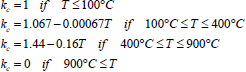
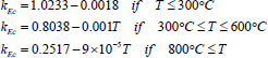
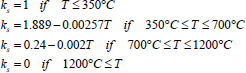
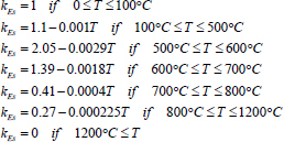
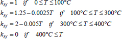
In thermal modeling, the STEELEC2EN model was adopted for reinforcement (steel and GFRP). CONCEC 2020 model in Eurocode 2 [20] was used to model concrete. In structural modeling, a normal concrete (NS CONCRETE) model was used. The reduction (kc) in compressive strength of concrete adopted in Eurocode 2 [20] was used. It is expressed by Equation 1, where T is the temperature. The reduction (kEc) in elastic modulus of concrete at high temperature recommended by Gernay and Franssen [21] is expressed by Equation 2. The reductions in yield strength and elastic modulus of steel at elevated temperatures recommended by Eurocode 2 [20] are expressed by Equations 3 and 4, respectively. The reductions in tensile strength (kf) and elastic modulus (kEf) of GFRP bars are expressed by Equations 5 and 6 [22], respectively.

2.2. Verifications
The available test results for RC beams exposed to fire were selected for verification. The RC beam in fire experimentally tested by Song et al. [23]was selected. Fig. (1) shows the configuration and details of the beam. The compressive strength of concrete was 25.8 MPa. Steel bars ϕ16 and ϕ25 had yield strengths of 445 MPa and 451 MPa, respectively. The concrete cover thickness was 25 mm. The elastic moduli of steel and concrete were 2×10⁵ MPa and 2.4×10⁴ MPa, respectively. The Poisson ratio was 0.3.
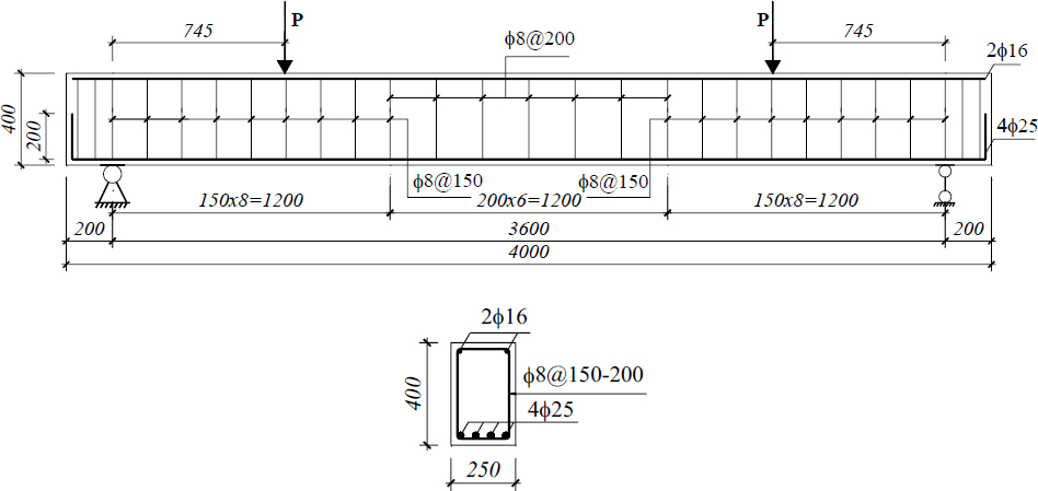
Beam B2 tested by Song et al. [23] (unit: mm).
Convection coefficient hot and convection coefficient cold were 25 and 4, respectively. Relative emissivity was 0.7. Thermal conductivity was 0.5. Moisture content was 1.43%. These are default values in SAFIR. The beam was exposed to fire on the bottom and two side surfaces, and the furnace temperature-time curve [23] is presented in Fig. (2). This fire was assigned for the bottom and two side surfaces, while the top surface was assigned by F20 because it was not exposed to fire. Fig. (3a) shows these assigned fire conditions. The cross-sections were meshed as shown in Fig. (3b). Fig. (4a and 4b) show examples of temperature distributions at 60 and 120 minutes, respectively. The fire duration significantly increased the temperature in the cross-section.
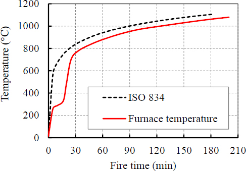
Furnace temperature-time curve [23] and ISO 834 fire curve.
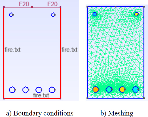
2D model for thermal modeling.
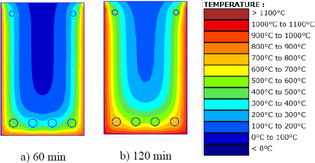
Temperature distributions in cross-sections at different fire times.
The deflection-time curves obtained from SAFIR and the experimental result [23] are compared in Fig. (5). The fire resistance obtained from the model was 185 minutes, which is close to the fire resistance of 192 minutes obtained from the experiment. The difference is only 3.65%, showing good agreement.
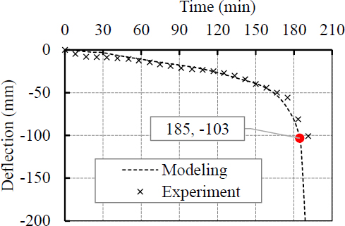
SAFIR and Song et al. [23] deflection-time curves.
A similar modeling procedure was conducted for the GFRP RC beam tested by Yu and Kodur [24]. The cross-section of the beam was 305 mm in width and 533 mm in height. The span length was 6010 mm. The tested beam was reinforced with 8 (19 GFRP bars), as shown in Fig. (6a). The convection coefficients for hot and cold are 25 and 4, respectively. The deflection-time curve obtained from the SAFIR model is plotted in Fig. (6b), compared with that from the experiment. The fire resistances obtained from the SAFIR modeling and the experiment were 67 minutes and 64 minutes, respectively. Thus, the difference is only 4.7%, indicating satisfactory model accuracy.
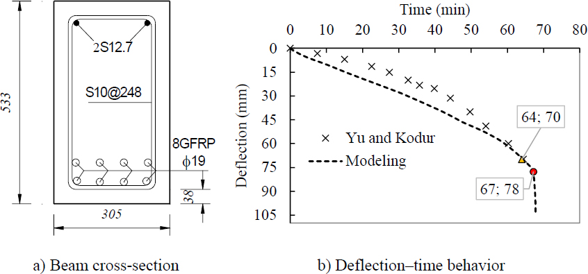
GFRP RC beam tested by Yu and Kodur [24] and comparison of deflection-time curves.
2.3. Hybrid GFRP-steel RC Beams for Analyses
Steel RC beams: The beam B2 tested by Song et al. [23] was modified for analyses. The analyzed beams had a cross-section of b × h = 250 × 400 mm and a span length of 3.6 m. Concrete had an equivalent compressive strength of 25.8 MPa. The longitudinal compression reinforcement was 2ϕ12 with a yield strength of 445 MPa. The longitudinal tension reinforcement was 5ϕ16 with a yield strength of 451 MPa and an elastic modulus of 200 GPa. Stirrups were steel ϕ8 with a spacing of 200 mm.
Hybrid GFRP-steel RC beams: ϕ16 GFRP bars were used to replace steel bars in the above steel RC beams. One, two, three, and four GFRP bars were used to replace one, two, three, and four steel bars in the tensile steel reinforcement, respectively, to produce four hybrid GFRP-steel RC beams.
GFRP RC beam: Five steel bars in the tension zone of the steel RC beam were replaced by five GFRP bars.
Table 1 summarizes the configurations of these beams. The value of ρf/fs varies from 0 to 1 with an interval of 0.2. Fig. (7) shows the cross-sections of these beams. GFRP bars had a tensile strength of 800 MPa, an elastic modulus of 45 GPa, and a Poisson coefficient of 0.2. The convection coefficients for hot and cold are 25 and 4, respectively.
| Combination | Reinforcement |
GFRP Area Af |
Steel Area As |
Total Reinforcement Area A = Af + As |
Ratio ρf/fs = Af / A |
|---|---|---|---|---|---|
| (mm2) | (mm2) | (mm2) | |||
| 1 | 5S16 | 0.0 | 1005.3 | 1005.3 | 0.0 |
| 2 | 4S16+1G16 | 201.1 | 804.2 | 1005.3 | 0.2 |
| 3 | 3S16+2G16 | 402.1 | 603.2 | 1005.3 | 0.4 |
| 4 | 2S16+3G16 | 603.2 | 402.1 | 1005.3 | 0.6 |
| 5 | 1S16+4G16 | 804.2 | 201.1 | 1005.3 | 0.8 |
| 6 | 5G16 | 1005.3 | 0.0 | 1005.3 | 1.0 |
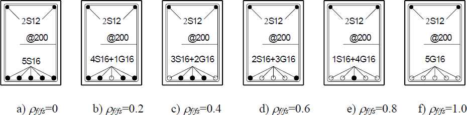
Hybrid GFRP-steel RC cross-sections of beams.
These hybrid GFRP-steel RC beams are exposed to fire from one surface (the bottom surface), two surfaces (the bottom and a side surface), three surfaces (the bottom and two side surfaces), and four surfaces. The applied fire was conforming to the ISO-834 standard fire, namely, FISO. The ambient temperature (F20) was assigned to the surface that was not exposed to fire. Fig. (8) shows beams exposed to different fire conditions. Fig. (9) shows an example of meshing, in which fine meshes were applied for reinforcement and adjacent regions to improve the accuracy of the models.
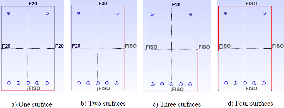
Beams exposed to different fire conditions.
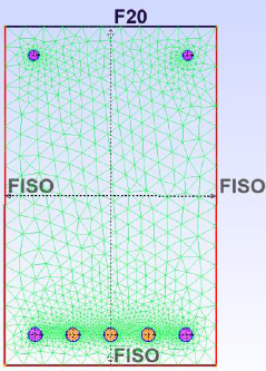
Meshing of the cross-section.
3. RESULTS AND DISCUSSION
3.1. Temperature Distribution in Hybrid GFRP-steel Cross-sections
Distributions of temperature in the cross-sections exposed to fire from the bottom surface are presented in Fig. (10a-g). The temperature at the bottom surface is the highest, while the temperature from the mid-height to the top surface is unchanged, although the fire duration is up to 420 minutes Fig. (10g). This is the explanation for the long fire duration when the beams were exposed to fire from only the bottom surface. When exposed to fire from two surfaces, the temperature in the cross-sections Fig. (11a-g) is significantly higher. The highest temperature is at the corner of the two fire-exposed surfaces.
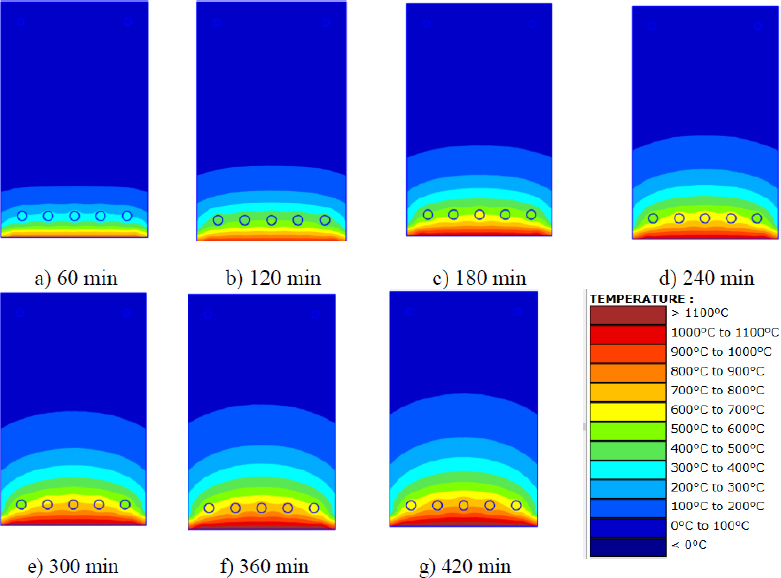
Distributions of temperature in cross-sections exposed to fire from the bottom surface.
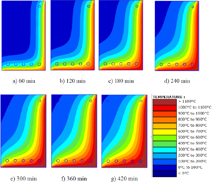
Distributions of temperature in cross-sections exposed to fire from two surfaces.
Exposed to fire from three surfaces Fig. (12) and four surfaces Fig. (13), the temperature in the cross-sections is significantly increased. The fire durations required to reach extremely high temperatures are also significantly shorter than those for cross-sections exposed to fire from one or two surfaces.
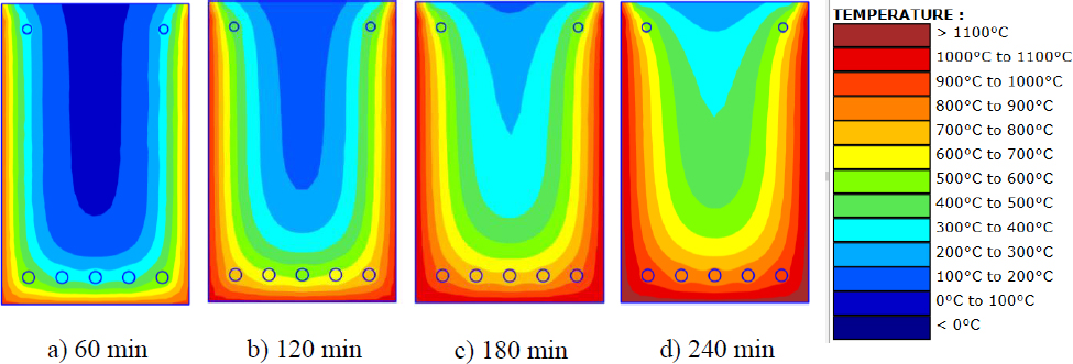
Distributions of temperature in cross-sections exposed to fire from three surfaces.
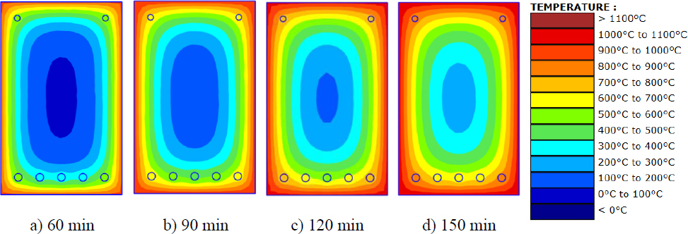
Distributions of temperature in cross-sections exposed to fire from four surfaces.
3.2. Deflection-time Behavior
Fig. (4) shows the deflection-time behavior of GFRP-steel RC beams with ρf/fs of 0.2, 0.4, 0.6, and 0.8 exposed to fire, respectively. In these figures, the points for the deflection rate and deflection limit, as defined in BS EN1363-1:2020 [25], were also plotted. Equations 7 and 8 show the limits, where L (mm) is the beam span length and d (mm) is the effective height.


Fig. (14) plots the deflection-time curves of hybrid beams with the bottom surface exposed to fire. The round points present the deflection limit, and the square dots present the deflection rate limit. The fire times of these points are analyzed. As shown in this figure, the deflection-time curve is shifted downward and to the left, indicating that GFRP reinforcement of beams in fire is less advantageous than steel reinforcement. Another point observed from this figure is that the point corresponding to the deflection limit occurred prior to the point of deflection rate limit for beams with ρf/fs of 0, 0.2, 0.4, and 0.6. However, when ρf/fs increased to 0.8 and 1.0, the deflection limit points occurred after the deflection rate limit. This is attributed to the faster reduction in the mechanical properties of GFRP compared with that in steel. Therefore, the fire resistance of the hybrid GFRP-steel beams is considerably affected by ρf/fs.
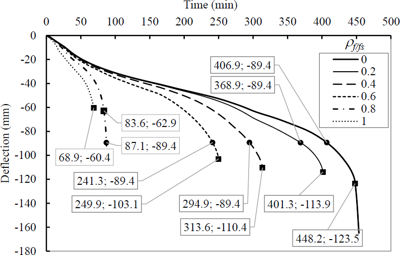
Deflection-time behavior of beams with bottom surface exposed to fire.
Figs. (15-17) show the deflection-time curves of beams with 2, 3, and 4 surfaces of fire exposure, respectively. These curves also exhibited a phenomenon similar to that described above. In Fig. 15, the two points of deflection rate limit and deflection limit are close to each other for beams with ρf/fs of 0.4 exposed to two surfaces. In Fig. 15, the deflection rate limit occurred prior to the deflection limit point. This result is due to the significant increase in temperature in the reinforcement, leading to a stronger reduction in its mechanical properties and, thus, the deflection rate limit occurring prior to the deflection limit.
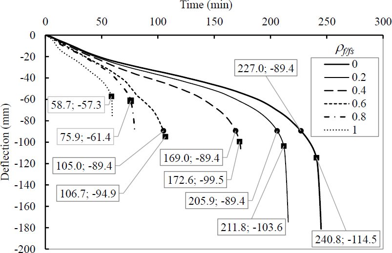
Deflection-time behavior of beams with the bottom surface and one side surface exposed to fire.
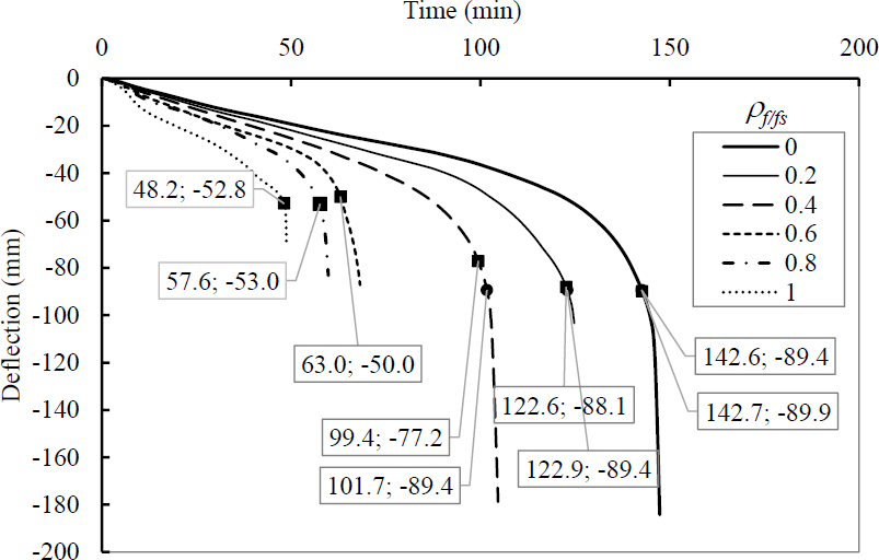
Deflection-time behavior of beams with the bottom surface and two side surfaces exposed to fire.
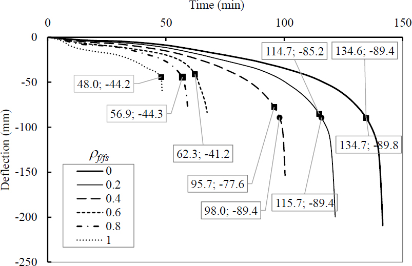
Deflection-time behavior of beams with four surfaces exposed to fire.
An important point observed in Figs. (14-17) is that the fire resistance reduces significantly as the number of fire-exposed surfaces increases. This result is attributed to the fact that the cross-section temperatures were significantly affected by the number of fire-exposed surfaces.
3.3. The Effect of ρf/fs on the Fire Resistance
Fig. (18a-d) plot the fire resistance of hybrid beams with different conditions of fire exposure. The fire resistance decreased significantly when ρf/fs increased from 0 to 1. Exposure to fire from the bottom surface, the fire resistance exhibited the strongest reduction with the increase in ρf/fs Fig. (18a). In contrast, the fire resistance exhibited the weakest reduction with the increase in ρf/fs Fig. (18d). The fire resistance of these hybrid GFRP-steel beams exposed to fire from the bottom surface is the highest, while that of beams exposed to fire from four surfaces is the lowest.
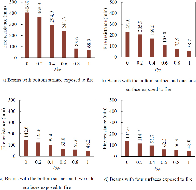
Fire resistance of hybrid GFRP-steel RC beams exposed to different fire conditions.
Exposure to fire from the bottom surface Fig. (18a), steel RC beams had a fire resistance of 406.9 minutes, which was reduced to 368.9, 294.9, 241.3, 83.6, and 68.9 minutes when the hybrid GFRP-steel RC beams had ρf/fs of 0.2, 0.4, 0.6, and 0.8. When the concrete beam was reinforced with only GFRP ρf/fs = 1), the fire resistance was 68.9 minutes. Therefore, compared with the fire resistance of the steel RC beam, the fire resistance of GFRP-steel RC beams with ρf/fs of 0.2, 0.4, 0.6, and 0.8) was reduced by 9.3%, 27.5%, 40.7%, and 79.5%, respectively. When ρf/fs increased to 1, the fire resistance was reduced by 83.1% compared with that of the steel RC beam. The fire resistance is significantly reduced with the increase in ρf/fs.
Exposure to fire from the bottom surface and one side surface Fig. (18b), the fire resistance of the steel RC beam (ρf/fs=0) is 227 minutes. The fire resistance is reduced to 205.9, 169.0, 105.0, 75.9, and 58.7 minutes for beams with ρf/fs of 0.2, 0.4, 0.6, 0.8, and 1.0, respectively. Compared with the fire resistance of the steel RC beam with ρf/fs of 0, those of beams with ρf/fs of 0.2, 0.4, 0.6, 0.8, and 1.0 were reduced by 9.3%, 25.6%, 53.7%, 66.6%, and 74.1%, respectively. Moving to the beams exposed to fire from three surfaces, these reduction percentages are 14%-62.2% when ρf/fs varies from 0.2 to 1.0, respectively. Similarly, the reduction percentages are 14.8%-64.3% when ρf/fs varies from 0.2 to 1.0, respectively.
3.4. Effect of Number of Fire-exposed Surfaces on the Fire Resistance
The effect of the number of fire-exposed surfaces of beams with the same ρf/fs on the fire resistance is examined as follows. Fig. (19a-f) show the fire resistance of hybrid beams with the same ρf/fs. These figures were plotted in the same axis limit coordinate system for visual comparisons. This figure indicates 1) the number of fire-exposed surfaces and 2) the importance of ρf/fs. Going from Fig. (19a) (ρf/fs = 0) to Fig. (19f) (ρf/fs = 1), the fire resistance reduces significantly. The effect of ρf/fs on the fire resistance is presented previously. The following paragraph focuses on the variation in fire resistance with respect to the number of fire-exposed surfaces.
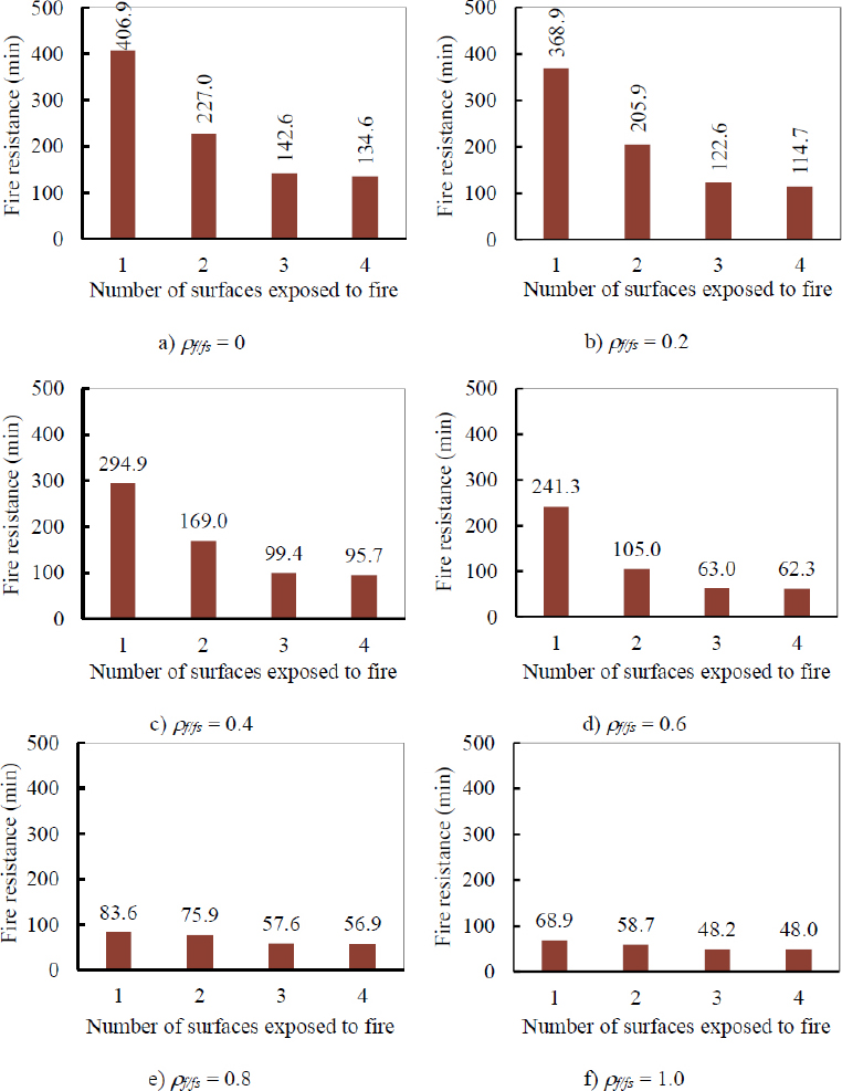
Effects of ρf/fs on the fire resistance of hybrid GFRP-steel RC beams.
For beams with ρf/fs = 0 (Fig. (19a), the fire resistance is 406.9 minutes when exposed to fire from the bottom surface. When the number of fire-exposed surfaces increases to 2, 3, and 4, the fire resistance reduces to 227.0, 142.6, and 134.6 minutes, respectively. The fire resistance of beams exposed to 2, 3, and 4 surfaces is reduced by 44.2%, 65.0%, and 66.9%, respectively, compared with that of beams exposed from the bottom surface. Beams with ρf/fs = 0.2 (Fig. (19b) exposed to 1, 2, 3, and 4 surfaces had fire resistances of 368.9, 205.9, 122.6, and 114.7 minutes, respectively. Therefore, exposing 2, 3, and 4 surfaces reduces the fire resistance by 44.2%, 66.8%, and 68.9%, respectively, compared with that of a beam exposed to fire from the bottom surface. With similar comparisons, the fire resistance of beams with ρf/fs = 0.4 Fig. (19c) and 0.6 Fig. (19d) has reductions of 42.7-67.5% and 56.5-74.2%. However, when ρf/fs = 0.8 Fig. (19e) and 1.0 Fig. (19f), the reductions in fire resistance are 9.2-31.9% and 14.8-30.3%, respectively. These reductions are presented in Fig. (20). When ρf/fs increases from 0 to 0.6, the reduction percentage increases. Further increasing ρf/fs results in a lower reduction percentage. These lower reduction values compared with the reductions in cases of low ρf/fs are attributed to the dominance of GFRP bars.
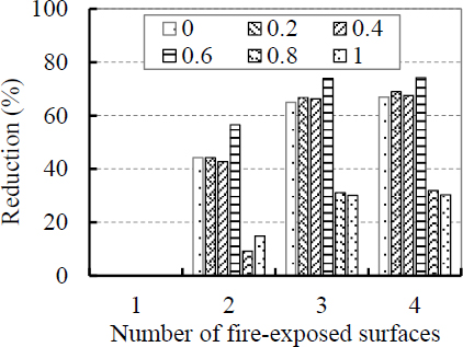
Reduction in fire resistance compared with the fire resistance of beams exposed to the bottom surface.
4. LIMITATIONS AND FUTURE WORKS
Further studies should be encouraged for different beam geometries, cover thicknesses, load levels, support conditions, and thermal boundary conditions.
CONCLUSION
Based on the obtained results, conclusions are drawn as follows:
• Both the fire conditions and ρf/fs detrimentally affected the deflection-time behavior and fire resistance of GFRP-steel RC beams. Combining the four fire-exposed surfaces and ρf/fs of 1 resulted in the worst deflection-time behavior and the lowest fire resistance for the beams.
• When ρf/fs increased from 0 to 1, the fire resistance of GFRP-steel RC beams was shifted from the state governed by the deflection limit to the state governed by the deflection rate limit. Increasing ρf/fs from 0 to 1 reduced the fire resistance by up to 83.1%.
• Increasing the number of fire-exposed surfaces from 1 to 4 detrimentally affected the deflection-time behavior of the beams. Compared with exposure to the bottom surface, exposure to 2, 3, and 4 surfaces significantly decreased the fire resistance by up to 74.2%.
AUTHORS’ CONTRIBUTIONS
The authors confirm their contributions to the paper as follows: D.V.D., V.V.C.: Study conception and design; D.V.D.: Analysis and interpretation of results; D.V.D., V.V.C.: Draft manuscript. All authors reviewed the results and approved the final version of the manuscript.
LIST OF ABBREVIATIONS
| BFRP | = Basalt Fiber Reinforced Polymer |
| CFRP | = Carbon Fiber Reinforced Polymer |
| CONCEC | = Concrete material model according to Eurocode 1992-1-2 standards |
| FISO | = Function representing the ISO 834 Standard fire curve |
| FRP | = Fiber Reinforced Polymer |
| F20 | = Constant ambient temperature function at 20°C in SAFIR |
| G | = Glass Fiber Reinforced Polymer bars |
| GFRP | = Glass Fiber Reinforced Polymer |
| NS CONCRETE | = Normal-Strength Concrete |
| RC | = Reinforced Concrete |
| S | = Steel bars |
| STEELEC2EN | = Steel material model according to Eurocode 1992-1-2 standards |
AVAILABILITY OF DATA AND MATERIALS
All data generated or analyzed during this study are included in this published article.
ACKNOWLEDGEMENTS
This research is funded by Vietnam National University Ho Chi Minh City (VNU-HCM) under grant number: B2024-20-08.